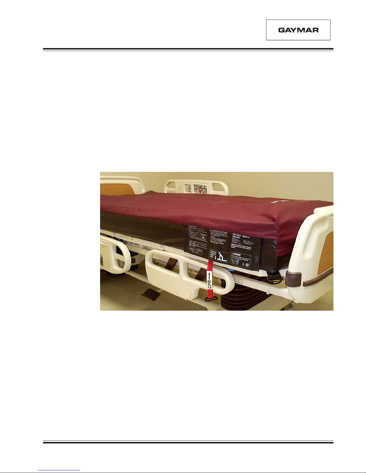
Sof•Matt®Low Air Loss Mattress System
Operator's/Service Manual
Gaymar and Sof•Matt are registered in the U. S. Patent and Trademark Office.
© 2001. Gaymar Industries, Inc. All rights reserved. www.gaymar.com
Before you begin . . .
WARRANTY
Sof•Matt Low Air Loss Mattress Systems are
warranted against defects in material and
workmanship under normal use and operation from
the date of shipment for a period of one year.
During the warranty period, Gaymar will repair or
replace at its sole option, free of charge, any
defective parts or products returned with prior
authorization prepaid to Gaymar Industries, Inc.
See Incoming Inspection and Return Policy.
Warranty does not cover products abused, misused,
or altered outside factory. There are no obligations
on the part of Gaymar for consequential damages
arising out of or in connection with the use or
performance of the product. Gaymar disclaims all
implied warranties including, but not limited to, the
implied warranties of merchantability and of fitness
for a particular purpose.
APPLICABLE SERIAL NUMBERS
This service manual applies only to models RSM176S
(no configuration) and RSM180S configuration ‘A’
Sof•Matt Mattress Systems. The 8th character
of the serial number identifies the configuration.
For example, S/N RSM180S A B10042
identifies a configuration ‘A’ system.
IMPORTANT
Please read all precautions and instructions before
using the Sof•Matt®Low Air Loss Mattress System.
Maximum benefit to the patient at the greatest margin
of safety requires a thorough knowledge and
understanding of the correct operation and
application of the Sof•Matt Low Air Loss Mattress
System.
Users must follow the instructions and precautions
included with each mattress system prior to use.
Operate the equipment with the same care you
would use when operating precision medical
equipment.
INCOMING INSPECTION AND
RETURN POLICY
Check the shipping carton for damage immediately
after receipt. If damage is discovered, the product
should be unpacked with the carrier’s agent present.
Make a claim immediately to the carrier for the damage.
Do not return damaged goods without notifying the
carrier. If products damaged during shipment are
returned to Gaymar without notifying the carrier,
Gaymar will assume that repairs will be made at the
customer’s expense. Products returned to Gaymar
must be accompanied by Returned Goods (RG)
numbers. Returned Goods authorization and numbers
may be obtained by calling Gaymar Industries'
Customer Service Department:
Toll free: 1 800 828-7341
Direct: (716) 662-2551
When inquiring, please supply model and serial number,
purchase order number, whether merchandise was
bought on contract, and reason for return.
In general, deleted and outdated merchandise will not
be accepted for credit. A restocking charge of 15% will
be assessed on returns of current merchandise.
Ship returns prepaid to Gaymar Industries, Inc.,
10 Centre Drive, Orchard Park, NY 14127-2295.
Sof•Matt Low Air Loss Mattress Systems purchased by
individuals for home use must be returned to the
dealer from which they were purchased for repair.
SYMBOLS USED
Attention: consult accompanying documents
Dangerous voltage
Double insulated. When servicing, use only
identical replacement parts.
Type BF applied equipment
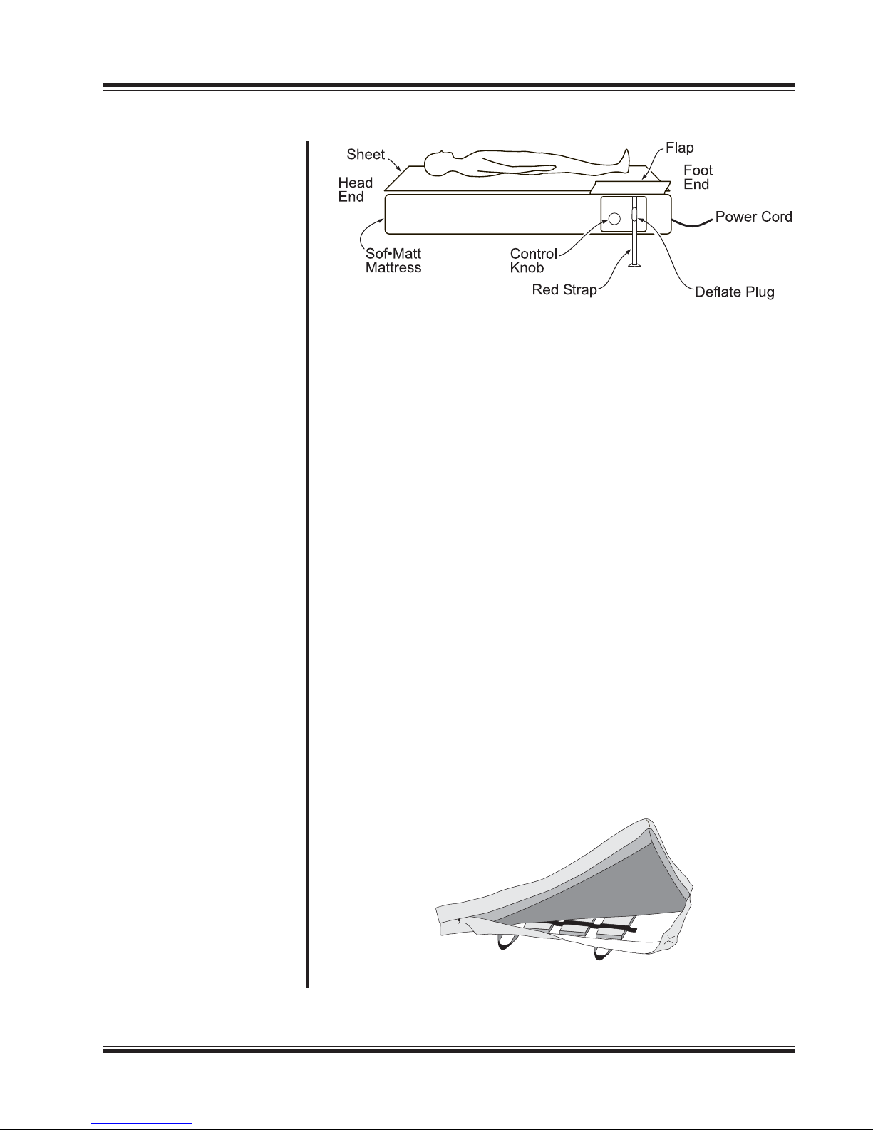
Pull red strap to rapidly deflate
mattress for performing CPR