SERVICE MANUAL
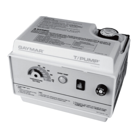
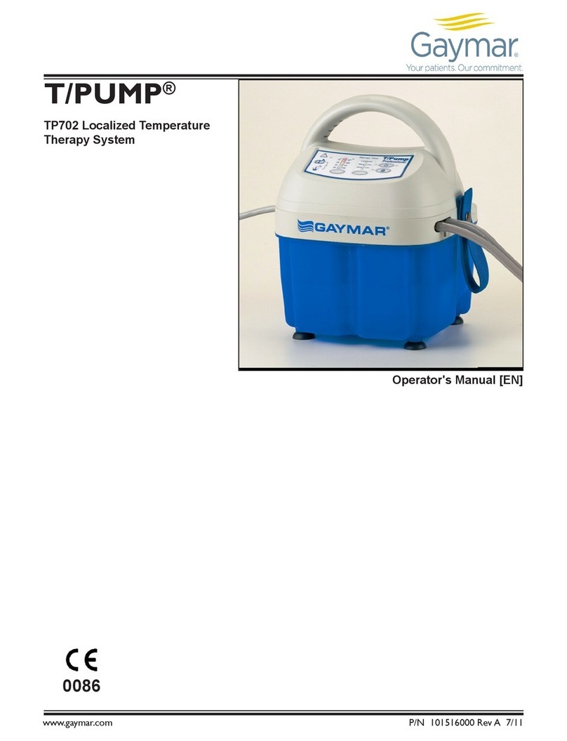
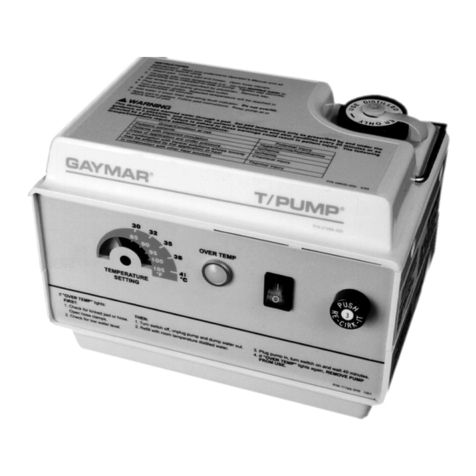
TP600 & 700 Series T/PUMP
2
BEFORE YOU BEGIN . . .
Read and understand this T/PUMP SERVICE
MANUAL and all SAFETY PRECAUTIONS
prior to servicing the T/Pump.
Only qualified medical service personnel should repair or
perform function tests on the T/Pump. Contact your
distributor for assistance:
CONTENTS
BEFORE YOU BEGIN . . ....................................2
SAFETY PRECAUTIONS.................................... 3
INTRODUCTION.................................................4
PUMP FEATURES .............................................. 6
KEYPAD FEATURES TP600 SERIES.................7
KEYPAD FEATURES TP700 SERIES.................8
KEYPAD FEATURES TP702................................9
SPECIFICATIONS..............................................10
CLIK-TITE®CONNECTORS.............................. 11
QUICK DISCONNECTS....................................12
START-UP PROCEDURE .................................13
SHUTDOWN PROCEDURE .............................13
STORAGE/CLEANING.......................................14
WATER TEMPERATURE CONTROL................ 16
THEORY OF OPERATION................................ 17
FUNCTIONAL CHECK ......................................18
DISASSEMBLY/REASSEMBLY..........................24
TROUBLE SHOOTING .....................................26
REPLACEMENT PARTS LIST... ........................32
WARRANTIES...................................................33
Figure 1.a & 1b....................................................4
Figure 2................................................................6
Figure 3................................................................7
Figure 4................................................................8
Figure 5................................................................9
Figure 6..............................................................11
Figure 7..............................................................12
Figure 8..............................................................17
Figure 9.a & 9b..................................................18
Figure 10............................................................21
Figure 11............................................................25
Figure 12............................................................29
Figure 13............................................................30
Figure 14............................................................31
SYMBOLS USED WITHIN THIS
MANUAL AND ON THE PRODUCT
Warm Water Fill Line
Cold Water Fill Line
Attention, consult Operator's
Manual.
Water Levels
Water Flow
Dangerous Voltage
Type BF Applied Part
Do not penetrate with sharp
object.
