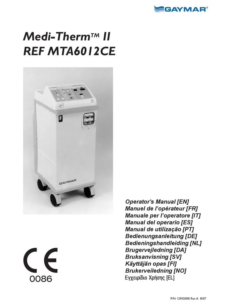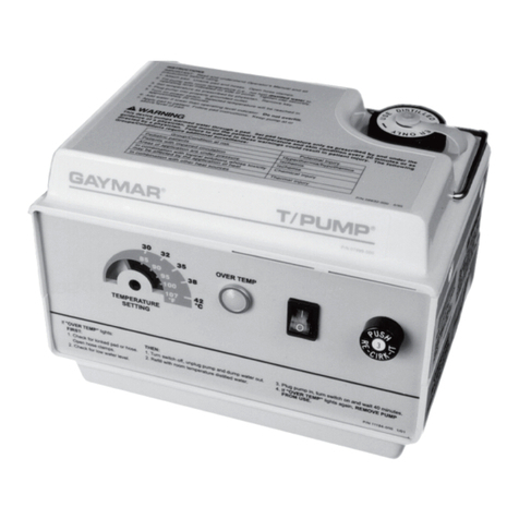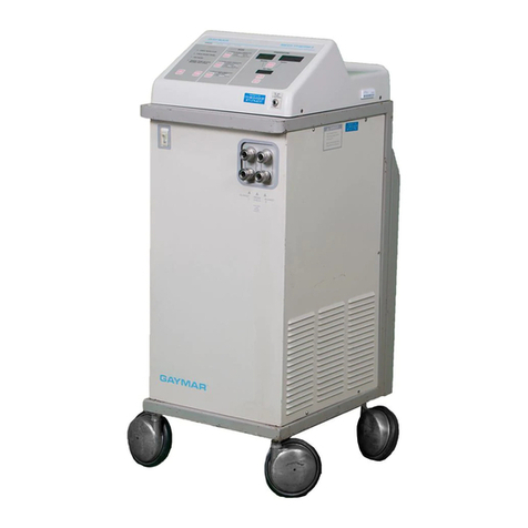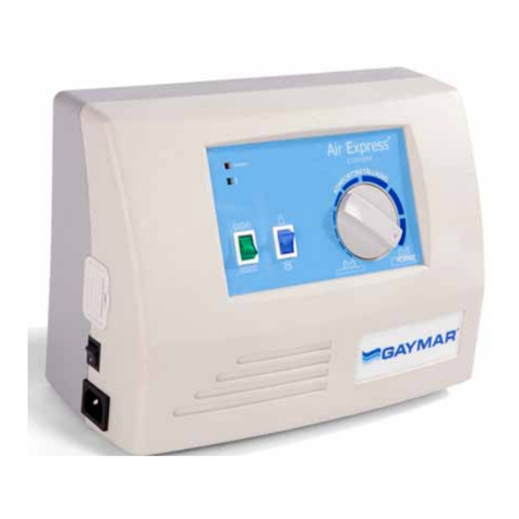
MTA7912 Service Manual
Important
• Refer to the Medi-Therm®III Operator’s Manual for detailed
operating instructions. Read and understand the Operator’s
Manual and all precautions prior to using the Hyper/
Hypothermia machine.
• Review the SAFETY PRECAUTIONS (see page 1) prior to
servicing the Medi-Therm III machine.
• For technical assistance, contact your local dealer.
Receiving Inspection
Upon receipt, unpack the Medi-Therm III machine. Save all
packing material. Perform a visual and mechanical inspection for
concealed damage by removing the wraparound from the chassis
(see gure 18, page 57). If any damage is found, notify the carrier
at once and ask for a written inspection. Photograph any damage
and prepare a written record. Failure to do this within 15 days
may result in loss of claim.
Refer to section 2.0 of this Medi-Therm III Service Manual for
additional details.
IMPORTANT
Before operating the Medi-Therm III machine, remove the
compressor shipping braces. See p. 74, gure B, items 8 and 9.
Temporarily remove the power cord retainer (g. 19, p. 58, item 6)
and install the power cord. Reattach the power cord retainer.
Before you begin . . .
Gaymar®and Clik-Tite® are registered in the U. S. Patent and Trademark Ofce.
Gaymar®, Clik-Tite®, and Medi-Therm®are trademarks of Gaymar Industries, Inc.
© 2009. Gaymar Industries, Inc. All rights reserved.
Table of Contents
1.0 Safety Precautions.................................... 1
2.0 Repair Policy............................................. 2
3.0 Specications............................................ 3
4.0 Blankets/Body Wraps/Accessories........... 6
5.0 Operator Control Panel............................. 8
6.0 Theory of Operation................................ 10
7.0 Functional Check, Safety Inspection,
and Preventive Maintenance .................. 17
8.0 Service Modes and Troubleshooting ...... 23
9.0 Repair Procedures.................................. 47
10.0 Service Information................................. 52
Figures
1 Water Warm-up Rate................................ 4
2 Water Cooldown Rate............................... 4
3 Disposable Probe/Reusable Cable........... 6
4 Medi-Therm III System ............................. 7
5 Medi-Therm III Control Panel.................... 9
6 Probe Check Well................................... 18
7 Functional Check/Inspection Form ......... 22
8 Initiating Service Mode 1 ........................ 23
9 RFU Codes............................................. 24
10A-N Troubleshooting Charts ..................... 27-46
11 Connecting Terminal Block Wires........... 49
12 Flow Switch............................................. 51
13 Temperature vs. Resistance Table.......... 52
14 Circuit Boards/Connectors (Head).......... 53
15A/B Heating Flow; Cooling Flow.................... 54
16 Refrigeration Flow Diagram.................... 55
17A/B Test Setup; Test Setup (alternate)........... 56
18 Machine Disassembly............................. 57
19 Parts Diagram (Base), Parts List ............ 58
20 Parts Diagram (Head), Parts List............ 60
21 Thermostat Wiring Diagram.................... 61
22 Control/Display Board, Parts List............ 62
23 Power Supply Board, Parts List.............. 64
24 Alarm/Backup Board, Parts List.............. 66
25 Wiring Diagram [foldout] ......................... 68
26 Power Supply Board Schematic,
1 of 4 [foldout]......................................... 69
27A Control Display Board Schematic,
2 of 4 [foldout]......................................... 70
27B Control Diplay Board Schematic,
3 of 4 [foldout]......................................... 71
28 Alarm/Backup Board Schematic,
4 of 4 [foldout]......................................... 72
29 Block Diagram [foldout]........................... 73
30 Shipping Instructions [foldout]................. 74
