Gfp 865DH-4 User manual

Gfp 865DH-4
March 2021
1
OPERATING MANUAL Gfp 865DH-4
Please read this manual carefully before operating!
Do NOT reproduce this manual or make changes to it
without express written consent from Gfp

Gfp 865DH-4
March 2021
2
Table of Contents
Contents Page
1. Introduction ……………………………………………………..
2. Important Safety Instructions…………………………………….
3. Installation Safeguards ………………………………………….
4. General Safeguards………………………………………………
5. Operating Conditions …………………………………………….
6. Electrical Requirements………………………………………….
7. Packing List………………………………………………………..
8. Installation
A. Uncrate the Machine……………………………………….
B. Remove Heat Tube Package…………………………………
C. Remove Machine from Skid……………………………….
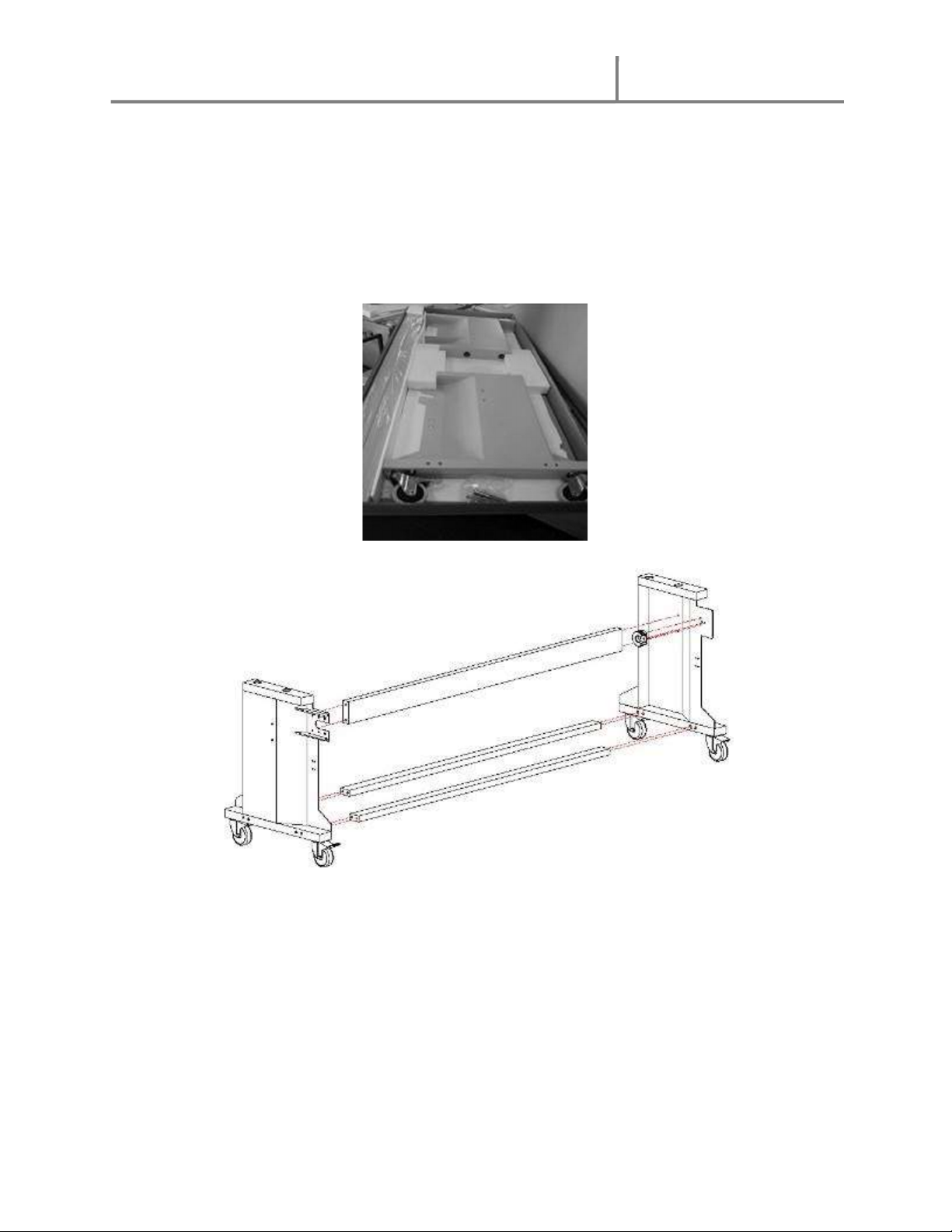
D. Assemble Machine Stand…………………………………..
E. Attach the Lower Supply Shaft Assembly
F. Set Machine on Stand…………………………………….…
G. Align machine to Stand…………………………………….
H. Install Front Media Unwind Shaft…………………………..
9. Installing the Heat Tubes
A. Inserting the Heat Tubes……………………………………….
B. Connecting the Electric Wires……………………………
10. Installing the Lower Rear Rewind ………………………………
11. Additional Installation Items …………………………………….
12. System Components………………..……………………………
13. Control Panel……………………………………………………..
14. Operation…. …………………………………………………….
15. Removing the Print Hold Down Assembly……………………….
16. Loading Film………………………………………………….…
17. Threading Film
A. Cold PSA Film…………………………………………….
B. Thermal Film Threading……………………………….…
C. Front Media Unwind…………………………………………..
18. Roller Pressure Adjustment..……………………………………..
19. Roller Gap Adjustment……………………………………………
20. Pull Roller Clutch Adjustment.……………………………………
21. Installing the Rear Rewind..………………………………….….
22. Troubleshooting
A. The Machine………………………………………….…….
B. Thermal Film Output…..…………………………….……
23. Specifications ……………………………………………………
24. Warranty …………………………………………………………
3
3
4
5
6
6
7
8
8
9
10
11
12
13
14
15
16
17
17
18
19
20
21
21
23
24
25
26
27
27
29
30
31
34
35

Gfp 865DH-4
March 2021
3
1.Introduction
Thank you for choosing a Gfp laminator. It has been designed and manufactured to provide
years of continuous service. Please read this manual thoroughly before operating. Please
inspect the box and the laminator for shipping damage. Damage should be brought to the
immediate attention of the delivering carrier. For a list of shipping components see
“Packing List” on page 7.
Please preserve this operation manual for future reference. Pay special attention to the
paragraphs with warning symbols which are vital to the proper uses and maintenance and
the safety of the users. Please comply with the operation guides of this machine and
warnings in this operation manual.
2. Important Safety Instructions
In this operating manual you will find important safety messages regarding the product.
Read these instructions carefully, failure to comply with the following safety procedures
could result in serious injury.
WARNING Do not attempt to service or repair the laminator. Only authorized
maintenance and service technicians should make repairs.
WARNING Do not connect the laminator to an electrical supply or attempt to
operate the laminator until you have completely read these instructions. Maintain these
instructions in a convenient location for future reference.
WARNING To guard against injury, the following safety precautions must be
observed in the installation and use of the laminator.
Warning Ensure the safety shield is in place before operating
the laminator. Operating without the safety shield can result in serious
injuries

Gfp 865DH-4
March 2021
4
3. Installation Safeguards
Shipping damage should be brought to the immediate attention of the delivering carrier.
Avoid locating the laminator near sources of heat or cold. Avoid locating the laminator
in the direct path of forced, heated or cooled air.
The receptacle must be located near the equipment and easily accessible.
Connect the electrical plug provided with the laminator to a suitably grounded
outlet only. This machine must have reliable earth ground to ensure the safety of the
machine during operations.
Contact an electrician should the electrical plug provided with the laminator not match
the receptacles at your location.
Ensure that the voltages of the power supply you are using match the rated
working voltages before operations. Do not use incorrect power supply.
Do not use damaged wires or outlets. If abnormal conditions occur, switch off
the power supply first.
This machine must be grounded reliably to ensure safe operation.
Only a licensed electrician should install wiring and outlet for the laminator.
To ensure safe operation, do not defeat or remove electrical or mechanical safety
devices such as interlocks, shields, guards and photo eyes.
This machine is equipped with a heating system; do NOT touch the surface of
rollers during thermal operations to avoid burns.

Gfp 865DH-4
March 2021
5
4. General Safeguards
Keep hands, long hair, loose clothing, and articles such as neckties and necklaces away
from the rollers to avoid entanglement and entrapment. The rollers have pinch points that
can trap body parts or clothing and cause serious injury.
Do not use the machines for purposes other than lamination and mounting, otherwise
damages to the machine or accidents may occur.
Keep out of reach of children.
Keep flammable and wet objects away from the machine.
Do not use flammable sprays or materials when cleaning the machine.
Do not leave the machine unattended during operations.
Do not mount metal materials or other hard objects.
Do not put burrs, sharp blade or rigid materials in between the two rubber rollers.
Do not attempt to laminate items that exceed total recommended material thickness of the
unit.
Do not touch the rollers when they are hot or place foreign object inside the machine.
Do not cut adhesive films directly on the surface of the rollers to avoid damaging the
rubber coating.
Shut down the machine after laminating to avoid misusing this machine by others.
Shut down the power and unplug the power cord before moving the machine.
Note the locations of the castors while moving or operating this machine to avoid injuries
to your feet.
Disconnect from the power supply before repair or maintenance.
Disconnect from the power supply when the machine is not in use for a long
time.
When the machine lies idle for a long period of time, raise the top rubber roller to avoid
flat spots on the rubber surface.
Do not cover the surface of the machine until the machine has completely cooled.
Perform only the routine maintenance procedures referred to in these instructions.

Gfp 865DH-4
March 2021
6
5. Operating Conditions
Place machine on level surface
Environment requirements:
o Ambient temperature: 50⁰ F - 104⁰ F
o Humidity:30%—80%;ideal humidity:55%
Due to the static on film rolls, you should try to keep the environment clean.
Provide enough space around machine to ensure safe and effective operation. The
minimum area covered is 8 ft. x 10 ft.
Do not directly cut the films on the surfaces of the rubber rollers to avoid damages to the
rollers.
Do not put burrs, sharp knives or extra thick and hard materials in between the rollers. Do
not leave objects like tools, rulers, knives, etc. on the working panels or the side cabinets
to avoid their being pulled into the machine accidentally and damaging the rollers.
For repairs and replacements, please contact your local dealer or distributor. Unauthorized
repairs and dismantling will affect future maintenances of the machines.
The machine can laminate continuously objects less than ½” thick.
o For objects over ½” but less than 1” thick, use the pedal switch.
Operator should be present while machine is in operation.
Warning: Do not keep the machines in direct sunshine or near it.
Do not keep the machine in dusty place or places with strong vibrations.
6. Electrical Requirements
220-240V 50/60 Hz Single Phase (NEMA 6-30R)
865DH-4 – 24 amp
Connect the electrical plug, provided with the laminator, to a suitably grounded
outlet only. This machine must have reliable earth ground to ensure the safety of the
machine during operations.
Contact an electrician should the electrical plug provided with the laminator not match
the receptacles at your location.
Ensure that the voltages of the power supply you are using match the rated working
voltages before operations. Do not use an incorrect power supply.
Do not use damaged wires or outlets. If abnormal conditions occur, switch off the power
supply.

Gfp 865DH-4
March 2021
7
7. Packing list
Remove all parts from shipping crate and boxes. Inspect parts and the machine carefully. Any
missing parts should be reported to your dealer or distributor.
Main Machine Crate Stand Box
Part Quantity Part Quantity
Main Machine 1 Cross beams 2
Swing out shaft assembly 1 Middle beam 1
Rewind tube 1 Left side stand 1
Foot Pedal 1 Right side stand 1
Heat tube 2 8 x100 hex screw 8
Media support brackets 3 Alignment bracket 2
Leveling Feet 4 5 x 8 hex screw 4
Stand anchor bolts (M10) 4 # 5 flat washer 8
Allen wrench 5mm 1 # 5 spring spacer 8
Film cutter (Zippy Knife) 1 Anchor bolts (M8) 2
Operation Manual 1 #8 Nut 2
8 x 20 hex screw 10 Allen wrench 4mm 1
# 8 flat washer 20 Allen wrench 6mm 1
# 8 spring spacer 20 5X16 hex screw 4
4X8 Combination screw 4 Spanner Wrench 1

Gfp 865DH-4
March 2021
8
8. Installation
8 A. Uncrating the machine
1. Remove bolts around the base of the crate.
2. Lift crate top straight up and off the skid.
8 B. Remove Heat Tube Packages
3. Remove nuts on heater support brackets that hold the cardboard tubes to the inside of the crate
and remove the heater packages.
Heat tube packages
Heat tube brackets

Gfp 865DH-4
March 2021
9
8 C. Remove Machine from Skid
1. Remove plastic cover and accessory box.
2. Raise the In-feed table (#1) and lock in place.
3. Remove rewind tube by pushing toward the spring side.
4. Remove supply shaft (#2) from the crate base by loosening the hex bolts on core adapters and
sliding to one side.
1. Infeed Table
2. Film Core Adaptor w/Brake
3. Lower Supply Mandrel
4. Shipping Skid
5. Bottom Swing-Out Shaft Assembly

Gfp 865DH-4
March 2021
10
8 D. Assemble Machine Stand
1. Remove stand from shipping box.
2. Bolt cross members to stand side frame.
3. Larger cross member goes in the center and takes the shorter bolts.
4. Use a flat washer and lock washer – Flat washer contacts the stand.

Gfp 865DH-4
March 2021
11
8 E. Attach Lower Supply Shaft Assembly
1. Bolt the bottom supply shaft assembly to the stand with 6 bolts by sliding the
shaft through the hole on the left side of the left stand
2. Bolt the cover to supply shaft assembly
3. Bolt machine alignment brackets to the outside of machine stand
5. Bolt the swingout shaft assembly to the stand with 6 bolts.
6. Bolt the cover to swing shaft assembly.
7. Bolt the machine alignment brackets to the outside of the machine stand.
Cover
Bottom supply shaft
assembly
Machine alignment
brackets
Brake
tension
adjustment
knob
Slide this end of the shaft
through the bracket hole
of the left stand
Lower Unwind Shaft
hole of left stand

Gfp 865DH-4
March 2021
12
8 F. Set the Machine on the Stand
1. Remove the machine from the bottom supports of the skid.
2. Lift the machine onto support stand using a FORKLIFT and moving straps that can lift 1000
lbs., to support the machine.
Heavy! Handle with care!!
NOTE: Bottom Supply Shaft on the stand goes to the Front of the machine
Bottom Supply Shaft
Front
Top Supply Shaft
Rear Rewind/Slitter Assembly
Media Unwind Shaft

Gfp 865DH-4
March 2021
13
8 G. Align the Machine to the Stand
1. Attach alignment brackets to outside of both stand legs
2. Insert one alignment anchor bolt through the bracket on the outside of the stand into bottom of
the machine on each side.
3. Secure the alignment bolt to the inside of the cabinet with the provided flat washer, lock washer
and hex nut.
NOTE: Failure to properly install the alignment brackets will result in the web skewing
which will end in costly ruined output.
4. Insert four (4) anchor bolts through the stand into the bottom of machine.
Anchor
Bolt
Anchor Bolt
Alignment bracket
Alignment bracket screws

Gfp 865DH-4
March 2021
14
8 H. Install the Front Media Unwind Shaft
1. Bolt left and right supply shaft brackets inside machine frame.
2. Insert Supply shaft and film core adaptors.
1. Supply shaft bracket 2. Supply shaft 3. Film core adaptor w/brake
2
3
1

Gfp 865DH-4
March 2021
15
9. Installing the Heat Tubes
Warning: Do not attempt this with the machine plugged in. Machine must be
unplugged and the power turned off!
9 A. Inserting the Heat Tubes
1. Remove Hand Wheels from right side cover.
2. Remove the right and left cabinet covers.
3. Remove left and right heater rubber cushion (2) from support brackets (4).
4. Insert heat tube through the core of the roller (longer heat tube on top).
5. Align ends with flat spots with flat side of rubber cushions.
6. Replace left and right heater rubber cushions.
NOTE: There is a lip on the inside of the roller; you will have to carefully cantilever the heat
tubes
1. Screw 2. Rubber cushion 3. Heat tube 4. Support Bracket 5. Roller
4
2
Lip

Gfp 865DH-4
March 2021
16
9 B. Connecting the Electric Wires
1. With the tube in place, remove the porcelain sleeve (1), porcelain cap (2), hex nut (3),
and flat washer (4) from both ends.
2. Connect the two ends to the electric wire connectors for both top and bottom heaters.
3. Replace flat washer, hex nut, porcelain insert and porcelain cap.
4. Replace side covers and hand wheel.
1. Porcelain sleeve 2. Porcelain cap 3. Hex nut 4. Flat washer 5. Electric wire connector
1
2
5

Gfp 865DH-4
March 2021
17
10. Installing the Lower Rear Rewind
1. Remove the spacer plates from each side of the machine.
2. Install the right-side bracket w/cradle with the supplied hardware.
3. Install the left side bracket with the Control Panel on the left side of the machine.
4. Insert the power jack into the corresponding receptacle.
NOTE: Holes with the paint removed will receive the bolts with the ‘star’ washers.
Spacer plates
S
ocket

Gfp 865DH-4
March 2021
18
11. Additional Installation Items
5. Check drive chains for tightness.
6. Check all drive set screws for tightness.
7. Check all electrical connections and input power and test for proper operation.
12. System Components
1. Left Side Cabinet
2. Emergency Stop Switch (E-Stop)
3. Linkage Shaft for pressure-
adjustment
4. Right Side Cabinet
5. Pressure-adjust Handwheel, Heat Rollers
6. Pressure-adjust Handwheel, Pull Rollers
7. Stand
8. Lower Supply Shaft
9. Core Adaptor w/Brake Assembly
10. Feed Tray
11. Bottom Swing-Out Unwind Shaft
12. Castor w/Brake
13. Top Swing-Out Supply Shaft
14. Top Rewind Shaft for Release Liner
15. Upper Supply Shaft Brake Assembly
16. Main ON/OFF Rotary Switch
17. Fuses
18. Lower Rear Rewind Control Panel
19. Foot Pedal
20. Lower Rear Support Bar
21. Upper Heat Sensor Bar
22. Upper Supply Shaft Axis Housing
23. Upper Rewind Shaft Clutch Knob

Gfp 865DH-4
March 2021
19
13. Control Panel
Note:
1. The machine does not have continuous Reverse. Reverse can only operate using the foot pedal.
2. If the photo-electric eye stops the machine, wait 5 seconds, move operation switch to “FOOT” then
back to “RUN” operation.
3. Temperature control knobs include ON/OFF switches. Full turn counterclockwise will turn heater
off.
4. Heat indicator lights will flash RED until they approach the set temperature, they will then flash
reddish green. Once they reach selected temperature, they will turn to solid GREEN.
3
6
1
2
4
5
7
8
9
10
1. Power Indicator
2. Top Roller Temp Display
3. Bottom Roller Temp Display
4. RUN/FOOT Switch
5. Top Heat Indicator
6. Bottom Heat Indicator
7. Top Heat Control Knob
8. Bottom heat Control Knob
9. FORWARD/REVERSE Switch
Speed Control Knob

Gfp 865DH-4
March 2021
20
14. Operation
1. General operation
Turn power to “ON” with the rear rotary power switch, POWER light on control will
illuminate.
2. Cold laminating:
When doing cold laminating, make sure both temperature dials are turned fully
counterclockwise to turn off heaters.
Adjust speed dial to desired position.
3. Top Heat Assist Laminating for PSA Films
Rotate TOP heater dial clockwise to turn on the top heater only.
Select desired temperature setting.
Recommended temperature setting for most applications with PSA film is dial setting
2 for approximately 100° F.
Recommended speed setting is dial setting 2 for 5 ft./min..
4. Thermal Laminating ( Encapsulation)
Turn both temperature dials clockwise to turn on both top and bottom heaters.
Select desired temperature and speed settings.
Recommended temperature settings:
a. Low temperature film ( activation temperature 185° F) - Dial setting 4 = +/- 200°
F
b. High temperature film ( activation temperature 210° F) - Dial setting 5 = +/- 230°
F
Recommended speed settings
Film gauge Dial ft./min
1.5 mil 4 8
3.0 mil 2.5 6
5.0 mil 2 5
10 mil 1.5 2.5
NOTE:
Recommended settings are starting points only and should be adjusted according to
quality of output achieved.
Excess heat may damage the printed image or cause waves. Insufficient heat may
result in ‘silvering’ and poor lamination.
Thinner stocks can be run faster while thicker stocks or heavy ink coverage should be
run slower.
Some stocks and ink-sets cannot be effectively laminated with thermal films.
Compatibility testing is recommended before laminating long runs.
NOTE: The surface temperature of the rollers is shown on the LCD readout. The LCD
does not work when the heaters are turned off.
Table of contents
Other Gfp Laminator manuals