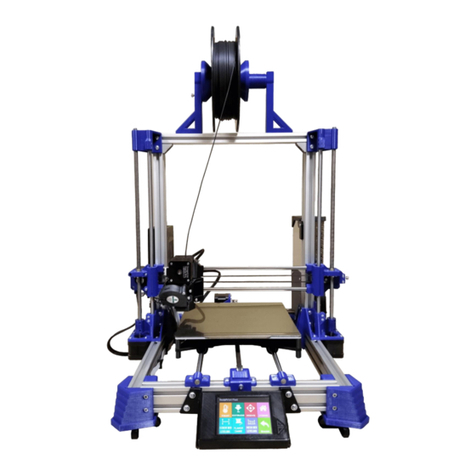
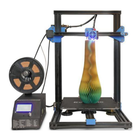
gCreate gMax 2 PRO User manual

Page 1
gMax 2 PRO
Updated 210827
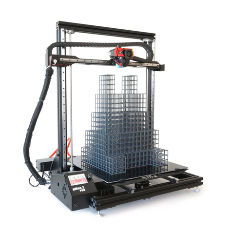
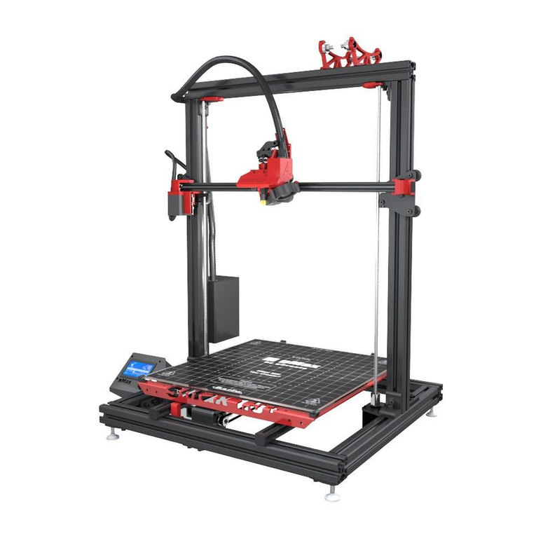
The gMax 2 Pro is a large format desktop FDM 3D printer. These machines can create an infinite number
of designs in all shapes, sizes, colors, and functionalities. The possibilities are truly endless. We at
gCreate hope you enjoy this machine as much as we have enjoyed making it. For the best experience
with your gMax, please review this user guide before operating and keep it handy for future reference.

Page 2
Cautions and Warnings
3D printing is a very fun and useful way to generate physical objects from your 3d models but it is still a
complex process with specific restraints.
•The gMax can accept new accessories including filament spool brackets, hotends, and
external peripherals, however unauthorized repairs or modifications that lead to
damage are not covered under the warranty.
•Prior to plugging in your printer, always inspect the printer for damage caused by
shipping or from a failed print. Be prepared to immediately power down (with the
power button) or unplug your printer in the event something undesired happens.
•Never open the electrical box when the printer is powered on. When performing any
electrical work, unplug it from the wall and let sit for several minutes to avoid any
possible electrical shock. Use a ceramic screwdriver when adjusting electrical
components
•As with any product utilizing high heat and electricity you should always have a proper
fire extinguisher nearby and always observe on the printer during operation.
•This machine must be always kept out of the reach of children and pets.
•This machines uses a very hot nozzle to melt plastic on to an acrylic or heated bed. You
should never leave the printer unattended and ensure the printer is placed on a sturdy
table with adequate free space around it. Do not place near combustible materials.
•At the beginning of each print you should verify the first several layers are adhering well
to the bed and that the print will not detach from the print surface. If your print pops off
the bed and the printer is unattended the printer may continue printing causing damage
to the hotend, extruder and/or bed.

Page 3
Contents
Basic Operation.............................................................................................................................................5
Loading Filament.......................................................................................................................................5
Inserting Filament.................................................................................................................................5
Changing Filament Manually ................................................................................................................5
Changing Filament Automatically.........................................................................................................5
Filament Runout ...................................................................................................................................5
Bed Leveling..........................................................................................................................................5
Using Your Printer.....................................................................................................................................6
Start from SD, USB or Host Software....................................................................................................6
Heated Bed Operation ..........................................................................................................................6
Setting Temperatures and Fan .............................................................................................................6
Removing Prints....................................................................................................................................6
The First Layer.......................................................................................................................................7
gcode Methodology ..................................................................................................................................7
gcode example:.....................................................................................................................................8
Common gcode commands ..................................................................................................................8
Updating Firmware ...................................................................................................................................8
Description............................................................................................................................................8
Printer Firmware (Marlin 2.x) ...............................................................................................................9
LCD Screen firmware ............................................................................................................................9
Firmware Error Codes.........................................................................................................................10
3D Models...................................................................................................................................................12
3D Modeling Software ............................................................................................................................12
Basic Concepts ....................................................................................................................................12
Free Software......................................................................................................................................12
Paid and Expert Software ...................................................................................................................12
3D Models From the Internet .................................................................................................................12
Overview.............................................................................................................................................12
Things to Watch Out For.....................................................................................................................12
Troubleshooting 3D Models ...............................................................................................................13
Machine Maintenance ................................................................................................................................13
Dust and Debris.......................................................................................................................................13
Lubricating linear rails.............................................................................................................................13
Tightening or replacing belts ..................................................................................................................13
X-Axis Belts..........................................................................................................................................14

Page 4
Y-Axis Belt ...........................................................................................................................................14
Stepper drivers........................................................................................................................................15
Adjusting the Power............................................................................................................................15
Replacing a Stepper Driver .................................................................................................................15
Hotend Maintenance ..............................................................................................................................16
Nozzle Clogged or Worn Out ..............................................................................................................16
Replace Nozzle....................................................................................................................................16
Replace Hotend...................................................................................................................................16
Loose Hotend Parts.............................................................................................................................16
BLtouch Replace Pin............................................................................................................................17
Replace Drive Gear..................................................................................................................................17
Tightening Bolts and Frame ....................................................................................................................17
Adjust Lead Screw...................................................................................................................................17
Lubricating the Lead Screws ...............................................................................................................18
Aligning the Lead Screws ....................................................................................................................18
Adjusting Bearings ..................................................................................................................................18
LCD Screen Breakdown...............................................................................................................................18
Buttons....................................................................................................................................................18
LCD Screen Machine Settings and Parameters...................................................................................18
Heating, Cooling and Extruding ..........................................................................................................19
Custom gcode .........................................................................................................................................20
Customer Notes ..........................................................................................................................................20

Page 5
Basic Operation
Loading Filament
Inserting Filament
You can insert filament with the extruder hot or cols.
1. Cut the end of the filament at a 45 degree angle.
2. Pinch the swing arm on the extruder and insert the filament so
it will be pinched between the drive gear and grooved
bearing.
3. Continue to push the filament until it reaches all the way
down to the heat block and nozzle. If the extruder is hot you
should see filament push out the end.
Changing Filament Manually
If you wish to change filament during a print you can go to “More > (Un)-Load”.A notification will ask
if you want to pause the print and if you click Ok it will initiate the pause allowing you to switch filament.
Changing Filament Automatically
To automatically initiate a filament change during a print, you can insert M600 in the gcode at the
desired move or layer height. Using this method, you can force a filament change at a specific time or
layer regardless of if you are present. See the gcode section for more information.
Filament Runout
The gMax printer comes equipped with a runout sensor that will pause the print if the sensor triggers.
Dual extruder printers have two sensors in series so if either one triggers it will pause the print and
remove the filament on the active extruder.
You can turn the runout sensor on or off via the LCD screen by going to “More > Features > Runout
sensor > Off”.
Bed Leveling
The gMax 2 uses Marlin firmware with Bi-linear bed leveling. The BLTouch sensor will probe the entire
bed to create a “mesh” of the bed as it travels around. You can see this by watching the z-axis couplers
move as the extruder travels.
G29 runs bed leveling but do not include it in your start gcode or it might not work correctly.

Page 6
Using Your Printer
Start from SD, USB or Host Software
Once you have sliced your file in your preferred software you are ready to print. For information on
slicing refer to the gCreate website or the slicing software webpages for tips and tricks.
•Put your *.gcode file on the SD card included with your printer and slide this in the left side of
the LCD screen. Then go to “Print > TFT SD” and select your file.
•Connect the printer to your computer using the supplied USB cable. The USB slot can be found
on the left side of the electronics case. Once connected you can send files to the printer from
Simplify3D, Cura, Pronterface or PrusaSlicer. These “host” software’s allow you to track
progress, send commands or control the printer.
•If you have the gTouch controller you can connect this via USB and operate the printer from the
secondary touch screen. You will have to put the touchscreen into “Classic Marlin” mode by
pressing the touchscreen for 3 seconds and selecting “Marlin”.
Heated Bed Operation
Setting Temperatures and Fan
You can set temperatures to the hotend or heated bed from the LCD
screen.
•To select a defined temperature, go to “Menu > Heat/Fan
> Preheat”. Make sure if you only want to heat the hotend
to switch from “Both” to “Hotend” or the printer will throw
an error.
•Go to “Menu > Heat/Fan > Heat” or just click the nozzle
icon from the main screen to pick a specific temperature.
•Go to “Menu > Heat/Fan > Fan” to set the fan speed.
Removing Prints
1. If the bed is acrylic, after the print finishes you can immediately remove it.

Page 7
2. If you are using a heated bed, turn it off and let it
cool several minutes before removing or you risk
damaging the print surface.
3. If the first layer printed correctly you should see
no curling at the edges.
4. USING CAUTION, take the scraper and gently tap
at the edges of the print. Look for corners of the
model and tap them. After several taps the print
should pop off the bed. If the model has a large
surface area on the print bed, it may be harder
to remove and you may have to slide the scraper
below the model.
The First Layer
Overview
The first layer of your print is perhaps the most important. Make sure that foundation is correct and the
rest of the structure has a better chance of surviving
Adjusting First Layer Height (Babystepping previously Live-Z adjust)
Bed Leveling with Heated Bed
gcode Methodology
gcode is what the 3d printer uses to move the extruder and issue commands. gcode can be modified in a
standard text editor such as Wordpad or Notepad++ and you should familiarize yourself with it.
Whenever you slice a model, the slicing program generates all the commands needed for the print and
outputs the gcode file. The gMax printer then will run these commands line by line with a buffer of 16
commands. Make sure all commands are in caps or the program will not work.
Common gcode commands either have a “G” designation or an “M” designation and you can set
parameters for many of these commands. Notes are added with a semicolon “;” and these won’t
execute.
You can also send gcode commands to the printer from your computer (via USB), or from the
touchscreen by going to “Menu > Terminal”. This is a useful way to test out gcode commands.
A full list of gcode commands can be found at https://marlinfw.org/meta/gcode/

Page 8
gcode example:
;I am a note. Insert lots of me to remember specific commands
M201 X800 Y800 Z50 E1000 ; sets maximum accelerations, mm/sec^2
M107 ; Turn fan off
M104 S245 ; set temperature
G28 ; home all axes
M109 S245 ; set temperature and wait for it to be reached
G21 ; set units to millimeters
G90 ; use absolute coordinates
M83 ; use relative distances for extrusion
G92 E0 ; Reset extruded amount
;TYPE:Skirt
;WIDTH:0.5625
G1 F1200.000
G1 X200.438 Y181.307 E0.06965 ; move extruder and extrude filament
G1 X201.273 Y181.349 E0.05195
M600 ; Initiate filament change
.
.
Common gcode commands
G28 ; Home all axis
G29 ; Level bed (Don’t use in start gcode)
M420 V1 T1 ; Display bed leveling data
M600 ; Initiate filament change
M107 ; Turn off fan
G1 X10 Y10 Z10 F1000 ; Move extruder to XYZ
position at “1000” speed
Firmware
Description
Firmware is the software that lives on the printer and LCD boards to control the printer. Firmware can
periodically be updated to unlock new features or fix existing bugs. Please make sure to download the
latest firmware for your printer from the gCreate websites and not directly from the source github.

Page 9
Upload Mainboard Firmware (Marlin 2.x)
The gMax 2 Pro uses the popular Marlin 2.x open-source firmware and it has been tailored for the
machine. Our edits to the firmware can be found on our forum or download pages. We offer pre-
compiled .bin files for the printer so updating is
quick and easy.
1. Option #1: Connect the printer to your
computer via a USB cable. You should then
see an external micro SD show up.
2. Option #2: Take out the micro SD card that
can be found inside the printer and put in
in your computer.
3. From your computer, download the
correct .bin file for your machine and put
it on the SD card (from option #1 or #2).
The file much be named “firmware.bin”
or the printer won’t recognize it.
4. Once you have transferred the file, put the card back inside the printer and turn it on. The
update will happen quickly and the way to check it is to go to “Menu > Settings > Info”to
check the date of the build. After the upload the file on the SD card will be named
“firmware.CUR”. If it isn’t then, the firmware didn’t upload.
Upload LCD Screen Firmware
The LCD screen has its own firmware, configuration file and graphics themes (with graphics and fonts).
We recommend updating all 3 whenever you update the firmware. Note the LCD screen can load
independently of the main board so make sure the mainboard firmware is properly installed before the
screen.
1. Download the correct zip file from our forum or website and
unzip to a spot on your computer. You should see a firmware
file, a config.ini file and a folder containing the graphics
theme.
2. Put all of these on the formatted SD card that came with your printer. Not the micro SD card.
3. Put this SD card in the LCD screen just like you are going to start a print and turn on the printer.
You will see the firmware, config files, fonts, and all the graphics update. It should take a few
minutes to complete. Once finished put the SD card back in the computer to see if the files are
renamed with a “.CUR” extension at the end. If not, format the card and try the installation
again.

Page 10
4. Note: You may need to go to “Menu > Settings > Machine > EEPROM > Reset” to properly
reset the print back to the factory settings after the firmware update. The printer will display
“Failed to enable bed leveling” after a reset because the bed leveling matrix has been erased.
Click OK and run bed leveling again.
Firmware Error Codes and Troubleshooting
•Homing Failed
oTypically, this error is a result of the extruder not recognizing the X or Y axis minimum
limits during homing. It also could be a result of the BLTouch not registering the home
or false triggering as the extruder lowers. Make sure the path is clear for the extruder
and any ribbon cables or wires are not loose.
•Heating Failed (Hotend and Bed)
oIf the hotend or bed fails to heat even 1 degree, after being instructed to do so, over 15
seconds it will trigger a heating failed event.
oCheck all the wiring and connections.
oMake sure your space isn’t too cold or the bed might have trouble heating.
oMake sure the bed is plugged in and the fuse isn’t blown (located where the power cord
plugs into the SSR).
•Thermal Runaway
oIf the hotend or bed registers a temperature far outside the target for a long period, a
thermal runaway will trigger to protect the printer and you. Check to see if the
thermistor is malfunctioning primarily by moving the wire when it’s set to a
temperature. If the temp jumps wildly you may need to replace the thermistor and/or
wire. Also inspect the wires and connectors for damage.
•Probing Failed
oTypically if your x-axis or bed is very far out of alignment, a probing failed event will
occur. This happens is the extruder is trying to probe a point below the safety margin.
Make sure your x-axis is level and your bed isn’t distorted. Make sure the bltouch pin is
dropping as you home and its not false triggering.
oProbing failed may occur if you place a G29 command in your gcode. Remove the
command and level the bed from the bed leveling menu.
•Min/Max Temp
oMin temp errors occur if the extruder or bed registers a zero temp as you are trying to
heat or start a print. Inspect the wires for damage and replace thermistors/wires if
necessary.
•Heating Failed
oIf the hotwend and or bed display a temperature but doesn’t heat it will trigger a
heating failed event after a period of time. Check the wires and connectors for damage.
Replace wires or connectors or heater cartridge if necessary.

Page 11
•Home offsets
oReset the printer to factory defaults. The home offsets may have been changed causing
the center of the bed to shift.
•LCD missing fonts/config mismatch
oYour LCD screen firmware may have become corrupted or mixed versions of firmware
and files were installed. Copy all the LCD screen firmware, icons and font data to an SD
card and restart the printer. See the LCD firmware section for more information on
installing firmware.
•Printer Connecting (Never Connects) / Printer Not Connected
oIf you reset the printer too quickly it may display this message. Turn off the printer and
wait a few seconds before turning back on.
oMake sure the baud rate has not changed on the LCD screen. It should be set to 250000
under “Menu > Connection > Baud Rate”.
oFrom the main screen press anywhere in the middle for 2 seconds and go to Classic
Marlin mode. You may have to rotate the knob for marlin to activate. It may prompt you
reset the EEPROM. Click OK if it does then go to “Control > Store Settings”.
oIf the printer has a black screen and marlin mode doesn’t load, you may have to reinstall
the firmware on the main board. Refer to the Section above.
oThe black 5 pin cable going from the electronics to the LCD screen might be damaged or
additional issues might exist. Contact tech support.
•Failed to enable bed leveling
oWhen you install new firmware or factory reset the printer, sometimes the bed leveling
matrix has been erased. Click ok, and run bed leveling again. Make sure to enable bed
leveling after it completes if it’s turned off.
•Printer halted Kill() called
The printer will stop if it detects an error. Click ok and from the main screen click the very top
left of the screen you to bring up a list of recent notifications to see what halted the printer.
oMin temp kill() called: If the printer beeps several times and a min temp warning then a
kill() called warning pops up the bed is trying to heat up but it’s not reading temperature
or it isn’t installed. Make sure the heated bed is installed and if you have the bed turned
on in your slicing software and if not, turn off the heated bed in the slicer or set the
temperature to zero.
oHeating Failed kill() called: If the printer is trying to heat the bed or the hotend and it
can’t the printer will show a heating failed message and the printer will halt. This is a
safety feature to prevent out of control heating. Look at the notifications, outlined
above) and see which part isn’t heating. If it’s the bed, make sure the bed is plugged in
•Echo

Page 12
oEcho commands are just messages informing the user of something and are not
necessarily errors or issues. For example, echo “Fade Height 10” is just letting the user
know the fade height for bed leveling is set to 10.
3D Models
3D Modeling Software
Basic Concepts
It is recommended that you have some 3D modeling experience. Often it is helpful to be able to
manipulate a model to get better results. Visit our YouTube page for tips and videos on 3d modeling.
Free Software
Blender, OpenSCAD, FreeCAD, Sketchup, Fusion 360 (trial version) and many more.
Paid and Expert Software
Solidworks, 3DS Max, Rhino, Maya, Fusion 360 (not the trial) and many more.
3D Models From the Internet
Overview
There are many different models that can be downloaded from the internet. Many of them are free to
download. If you need something printed and you think someone else probably wanted it as well
chances are you can find it, or something similar on the internet. Among the most popular 3D printing
file sharing platforms are Cults3D, Thingiverse, CGTrader, Threeding , GrabCAD and MyMiniFactory.
Things to Watch Out For
Anyone can create models and upload them to the internet, and because of this many great designs are
shared and distributed all over the world. Unfortunately, there is no guarantee that a model from the
internet is going to print successfully and no guarantee that it will work as it is described.
You should thoroughly inspect models you find on the internet. Not every printer is the same. Some
models will not print on FDM printers like the gMax as they were designed for other technologies.
Make sure the models are watertight solid models that do not have intersecting faces.
Refer to the gCreate forum and gcreate.com for articles on 3d model issues.

Page 13
Troubleshooting 3D Models
Machine Maintenance
Dust and Debris
The gMax was designed with robust components however all machines are susceptible to dust and
debris causing performance issues especially if the electronics are not
getting proper cooling.
We recommend blowing out the fans on the power supply, inside the
electronics case and on the extruder often.
Make sure to clear loose filament or debris from the belts, pulleys, and
guide rails. Also make sure to use the supplied metal bristle brush to
clean filament off the nozzle when it is hot
Lubricating linear rails
The gMax 2 Pro uses Hiwin linear guide rails and blocks. The guide blocks contain rows of recirculating
ball bearings and it performs best when lubricaled and clear of debris.
The X and Z axis use Hiwin MGN15C rails and the Y axis
uses EGH15C rails.
Warning. Do not remove the linear block from the rail
without the use of a plastic stopper or you risk having
the ball bearings fall out and ruin the block.
To clean and lubricate the rails we recommend wiping
them clean with a paper towel and spraying with
CorrosionX (http://www.corrosionx.com) ensuring the
lubricant gets inside the bearings.
Tightening or replacing belts
The gMax printer uses 6mm wide GT2 fiber reinforced timing belts. Use the guide below to replace or
tighten the belts. Do not use metal reinforced belts as the tight radius of the pulleys will weaken the
metal fibers over time causing the belt to break.
Figure 1
Plastic stoppers used to prevent ball
bearings from falling out.

Page 14
X-Axis Belts
The gMax 2 Pro was designed so the x-axis belt will remain in-place even if you swap extruders. A metal
plate is bolted to the x-axis linear block and the belts are attached to either end. You do not need to
remove the extruder to replace or tighten the belts.
If you need to tighten or replace a belt, follow these steps.
1. On the x-axis motor, remove two of the bolts (#1 and #4).
2. Loosen the other two bolts (#2 and #3). This will allow the motor
to swing down and loosen the belt.
3. If you’re installing a new belt, connect it to the right side of the
extruder plate with cable ties, then loop it around the right-side
pulley, around the motor on the left side and
connect it to the left side of the belt plate. The belt
should be tight enough that it’s not sagging.
4. Once everything is connected rotate the x-axis
motor back up to tension the belt and reinstall the
bolts.
Y-Axis Belt
The y-axis belt clamp is secured underneath the bed frame. We must access the bottom of the printer to
adjust the belt tension. To do this turn the printer on its back. You will find it useful to use a box to rest
the printer frame on. A filament box is the perfect size. As you lift, the bed will want to roll backwards.
Be sure to hold it while turning the printer on its back
1. With access to the bottom of the printer, loosen the aluminum bracket from the aluminum
extrusion. So it has a few millimeters of wiggle room.
2. Loosen the double t-nut that is pressed against the belt
on the back of the plate.
3. Insert the new belt or tighten the belt by a tooth or two
if you are just tightening the belt.
4. Then tighten down on the double t nut to clamp the belt
in place. The belt should not be tight at this point
because the aluminum bracket is loose.
5. Tighten the aluminum bracket back down. Tightening down on the aluminum bracket will pull
the belt tight.

Page 15
Stepper drivers
The gMax 2 Pro uses TMC2130 stepper drivers. The drivers have an adjustable potentiometer on the
top for adjusting the maximum current. You can also adjust the current to the drivers from the LCD
screen.
Make sure you have proper cooling in the electronics case or the drivers can and will overheat. When
the drivers overheat the firmware will automatically reduce the power to the drivers, in 50ma
increments, to avoid damage but this could lead to lost steps.
NOTE: Whenever you are adjusting any of the electronics, turn off the printer, unplug it and wait a few
minutes to ensure the power has drained from the system.
Refer to the wiring diagram for more information on which axis is controlled by which driver.
Adjusting the Power
We recommend using a ceramic screwdriver when
adjusting the stepper drivers to avoid damage to the
electronics.
The potentiometer will have a small flat spot on it
which should be turned to about a 45 degree angle.
Turn Clockwise to increase current (power) and
counter clockwise to decrease it.
Note: The driver current is also set via the firmware. See “Driver Current”in the “LCD Breakdown >
Parameters”section of this guide.
Replacing a Stepper Driver
If you need to replace a stepper driver, it can be pulled out of its
socket. You may need to loosen the bolt holding the electronics
to the frame to allow you to swing out the electronics for easier
access.
We recommend rocking the driver slightly back in forth while
pulling it out.
If you need to unplug the motor wire for easier access make
sure to pull on the connector and not the wires or you risk
pulling the wires out.
Install the new driver in the same orientation or you risk damaging the machine.

Page 16
Hotend Maintenance
Nozzle Clogged or Worn Out
If your nozzle clogs it could be from a number of issues. If you use a lot of high temp or specialty
filaments and they remain on for 24+ hours, carbon can build up in the nozzle resulting in clogging.
We recommend changing nozzles often especially if you have important prints. Alternatively you can get
hardened or ruby nozzles to extend the life.
You can usually spot a worn out nozzle if the print/infill looks spotty or the printer looks like it’s under
extruding. It will look like it’s not connecting the infill lines or they are just dots. This can also happen
from picking the incorrect nozzle size in your slicing software.
Replace Nozzle
Replacing a nozzle is easy, quick and should be done often.
1. Make sure to heat your extruder and remove any filament.
2. Using a 7mm socket and adjustable wrench, loosen the nozzle while holding the heater block
with the wrench. Make sure all the force goes into the wrench, so you don’t break the heater
throat.
3. Once removed, replace the nozzle with a fresh new one and make sure it’s very tight, again
using the wrench. Do not tighten without the wrench or you may loosen the heater block or
break the throat.
4. You might have to adjust the babystepping on the next print since the new nozzle may be a new
height.
Replace Hotend
You may have to replace the entire hotend if parts break or you need a whole new assembly.
The hotend has two electrical connections. One is a thermistor (temperature sensor) and the other is
the heater cartridge (that heats the filament). Both of these plug into the extruder with simple
connectors.
1. Turn the printer off. Then disconnect the electrical connections mentioned above.
2. Loosen the two bolts holding the hotend in place. Use the hex keys that came with your printer.
3. Remove the old hotend and install the new one in its place.
4. Connect the heater and thermistor wires and test the printer.
Loose Hotend Parts
Make sure to periodically check your hotend for loose parts due to vibration or other issues.
•On the 3D printed extruder bracket. Tighten the (3) M3 bolts holding the bracket in place fairly
tight. The 3rd bolt holding the swing arm should be tightened then backed off a half turn to allow
it to swing freely.
•Make sure the bolts holding the extruder to the x-axis bracket are always tight. If they are loose
you may experience irregular layering in the z-axis.

Page 17
•Make sure the swing arm M4 bolt holding the U groove bearing is tight.
BLtouch Replace Pin
If the pin on your BLTouch leveling sensor broke off, you can easily replace it.
1. Turn off the printer.
2. Remove the (2) bolts holding the BLTouch to the extruder bracket allowing it to drop down.
3. On the top of the sensor, remove the set screw allowing the pin to be removed from the top.
4. Insert the new pin, and tighten the set screw until its flush with the top of the sensor housing.
5. Reinstall the sensor on the gMax extruder.
Replace Drive Gear
The gMax uses a hardened steel sharp drive gear to push the filament into the extruder. It may wear
down after long usage and replacing it is simple.
1. Loosen the set screw on the drive gear using a hex key.
2. Pull it off the motor shaft.
3. When installing the new one you will see a flat spot on
the gear that will match a flat spot on the motor shaft.
Slide it on and tighten the set screw.
4. Make sure the set screw is not in the path of the
filament.
Tightening Bolts and Frame
Due to temperature differences and plastic fatigue, you should check the bolts on the gMax periodically
to ensure they are tight.
Common areas to check are:
•The extruder assembly where it attaches to the x-axis.
•The extruder hotend bolts.
•Extruder bolts. Make sure the swing arm can still swing freely.
•Bed carriage where it connects to the linear rail blocks. M4 button head bolts.
•Runout sensor switch sensor.
Adjust Lead Screw
The gMax 2 uses a TR10*4 lead screw and a machined POM nut. The lead screw is 10mm and has a
4mm pitch to combine speed and accuracy.

Page 18
Lubricating the Lead Screws
DO NOT use any oil or liquid lubrication on the lead screw as the POM nut will not operate properly.
Instead clean off the lead screw by using acetone or rubbing alcohol on a paper towel or cloth while
running the z-axis up and/or down. You can also use a cotton string by pulling it across one of the
threads as you move the z-axis up or down.
Aligning the Lead Screws
If the z-axis is binding or the lead screws come out of alignment, there are 4 spots you can loosen and
adjust.
1. Loosen the set screws from the coupler attached to the motor and make sure the lead screw is
straight. We recommend tightening the set screws a little at a time alternating between them
each time to ensure it stays straight. Look for a flat spot on the lead screw to line up with one of
the set screws.
2. Loosen the two bolts holding the lead screw to the x-axis carriage and POM nut and let it settle
in the correct position. Then re-tighten.
3. Loosen the top pillow bearing plate where it connects to the frame of the printer. Then run the
x-axis arm to the top and re-tighten the plate wherever it settles.
4. Lower the x-axis arm slightly from the top so you can loosen and re-tighten the set screws on
the top pillow bearing (attached to the top of the lead screw).
Adjusting Bearings
LCD Screen Breakdown
The gMax 2 PRO uses a 3.5” responsive touchscreen with an STM32 processor and open source
firmware. The screen firmware is independent of the printer firmware and must be updated separated
via an SD card. Note, due to it’s open-source nature, some settings are visible that so not pertain to the
gMax 2 PRO. Review the categories below for more information.
Buttons
LCD Screen Machine Settings and Parameters
Menu > Settings > Machine > Screen

Page 19
Re-calibrate the screen if needed.
Menu > Settings > Machine > Features
Various features that can usually be turned on or off like the power loss recovery, filament
runout sensor and other options. Many of these features are available during a print as well.
Notes:
▪Runout sensor: Set to on or off. Smart is not utilized.
▪Power loss recovery: recovers current layer in touchscreen mode. Recovers
exact position in classic Marlin mode.
▪Auto power: Not used.
Menu > Settings > Machine > Parameters
Features and variables that are set in the marlin firmware such as TMC bump sensitivity
(sensorless homing), steps per mm and driver current. Typically these settings do not need to be
modified.
▪TMC bump sensitivity: Threshold for sensorless homing of the X and Y axis. If it
is too low could lead to false triggers. 10 recommended
▪Driver Current (mA): The TMC2130 stepper drivers can have the current
adjusted via the firmware. If the drivers overheat the printer will dynamically
lower the current to cool them down. The default value should be 1000
Menu > Settings > Machine > EEPROM
The EEPROM is where settings are stored to memory such as machine parameters, settings and
features.
•Save: Save the current changes to memory
•Restore: Restore the settings to the defaults when you last turned on the printer (if other
changes were made and not saved to memory)
•Reset: Reset the printer to the factory default settings. You will need to re bed-level, adjust the
baby stepping and change anything else that was modified since the last firmware update.
Heating, Cooling and Extruding
Menu > Heat
Used to preheat the extruder/hotbed, modify temperatures or shut off heating.
Menu > Fan
Used to turn on/off the extruder fan or set it to a particular percentage.
Menu > Extrude

Page 20
You can preheat the extruder and purge filament. Useful with switching materials or colors.
Additionally you can run the Purge command from the Menu > Custom button.
Menu > Settings > Machine > Tuning > PID
PID Tuning: Used to recalibrate the heating cycle when a hotend or heated bed is reaching the
target temperature. Useful to calibrate when changing environments. Simply pick a temperature (ex.
200 for the extruder) and hit start. Then let the process complete.
Custom gcode
The gMax 2 PRO has several useful custom gcode routines pre-installed. Up to 15 routines can be
utilized and they can be added by modifying the config.ini file. Note to add your own custom routines
you must use “/n” between gcode commands to add new lines.
Raise Z 100
Raise the z axis 100mm. Useful for changing nozzles or cleaning the hotend. Press twice to get
enough clearance for changing nozzles.
Level X-Axis
Can be used to mechanically level the x-axis and set a baseline before a print. The printer will
home then the extruder will move all the way to the right off the bed. The extruder will then lower
below the bed until the x-axis arm bumps against the side plates then it will raise back up. This process
can be repeated and the printer must be bed leveled after it is complete.
Preheat PLA Both
This will preheat both nozzles (for dual chimera extruders) to 200C.
Customer Notes
Maintenance
Other manuals for gMax 2 PRO
2
Table of contents
Other gCreate 3D Printer manuals
