GDZX ZXJB User manual

ZXJB Single Phase
Relay Protection Tester

- 1 -
Contents
Ⅰ、Product Introduction............................................................................- 2 -
Ⅱ、Technique index....................................................................................- 2 -
Ⅲ、Panel layout diagram and function................................................. - 3 -
Ⅳ、Output power supply operation....................................................... - 4 -
Ⅴ、Instructions............................................................................................ - 5 -
Ⅵ、Matters Need Attention..................................................................... - 10 -
Ⅶ、Packing list........................................................................................... - 11 -
Ⅷ、Maintenance and Repair................................................................... - 11 -

- 2 -
Ⅰ、Product Introduction
ZXJB Single Phase Relay protection Tester the updated generation product
developed by our company. It adopts latest power source technology, which make
this instrument reach International standard and domestic advance level in circuit
design, component selection, panel layout and internal structure. It is with powerful
functions, excellent materials, clear testing project data, simple operation and ideal
for Power Industry relay protection department.
Ⅱ、Technique index
1. Working condition
1) Working power supply:AC220V+10% 50Hz
2) Working environment:temperature:-10℃~40℃;humidity:≤85%
3) Atmosphere Pressure:86~106Kpa
2. Output power supply
1) AC voltage:0~250V/3A
2) AC current:0~100A/7.5V;0~20A/25V;0~5A/5V
3) DC voltage:0~220V/3A
4) DC current:0~20A/25V
5) Setting output:DC24V DC48V DC110V DC220V
3. Performance index
1) Voltmeter, ampere meter :41/2digit
2) Digital Millisecond Meter:0~99.9999s
4. Function
1) Measuring relay: measure start value, return value, drop-off to pick-up ratio of
current, voltage relay.

- 3 -
2) Time relay: Measure start value, return value and action time, error less than
0.2ms
3) Intermediate relay: Measure start value, return value, holding value and action
time of coil 4)
4) Reclosing relay: Charge test of capacitance, charge time, reclosing time and
middle components test.
5) Differential relay: DC Excitation test, Braking test, Volt-ampere characteristic test.
6) Other unconventional relays and LV circuit breakers.
Ⅲ、Panel layout diagram and function
Panel layout diagram:
1
Function description
1) J1、
J2、
J3、
J4、
J5 are respectively AC, DC power source and setting value output
terminal, as it shows in the panel
2) X1 indicates current voltage value ( display starting value, return value and rated
value), X2 is Millisecond Meter
3) S1 is power supply socket, S2 is power switch
4) T1: Power source output Selecting knob T2: Setting value output selecting knob
T3: contact state selecting knob ( means the lamp can be used to judge the

- 4 -
operating value and return value. I means normally open contact off delay is
closed, II means normally open contact off delay is open. III means normally
closed contact off-delay is open. IV: normally closed contact off-delay is closed.
T4 is power supply output value regulation knob
5) Contact: the wiring terminal of the tested relay contact
Remark: There should be no external power source for the relay contact
when test replay operating time. And J1、J2、J3、J4、J5 shouldn’t be
short-circuited
6) Z:power supply output type
7) Operating indication:indicate at contact operation ( if connect with normally open
contact, the indicating lamp will be turned on after operation, and if connect with
normally closed contact, the indicating light will be off after operation)
8) Synchronization: control the on-off of the output voltage current, to make short
t e s t o n r e l a y r a t e d v a l u e .
9) Set: setting value output switch
10) Reset: clear operation for Millisecond meter
11) Reclosing: closing signal sending terminal of the reclosing reply
Ⅳ、Output power supply operation
1. AC voltage(0~220V)output
Turn T1 to AC250V, close the synchronous switch, turn T4, J2 terminal to output
0~250V voltage. X1 indicates the present voltage, output type ACV light will be
on
2. AC current (0~5A、0~20A、0~100A)output
Turn T1 to AC5A
(AC20A、
AC100A)
, close the synchronous switch, turn T4, J1

- 5 -
terminal to output 0~5A(0~20A、0~100A)AC current, X1 indicates current
voltage, output type ACV light will be on
3. DC voltage(0~220V)output
Turn T1 to DC250V, close the synchronous switch, turn T4, J3 terminal to output
0~220V DC current, X1 indicates present voltage, output type ACV light will be
on
4. DC current(0~20)output
Turn T1 to DC20A, close the synchronous switch, turn T4, J4 terminal to output
0~20V DC current, X1 indicates present current value, output type ACV light will
be on. Note: When regulate the current, it must not be over rated current. Or else
it will damage the instrument.
5. Setting value output
1) Turn T2 to 24V,close set switch,J5 terminal output constant DC voltage 24V
2) Turn T2 to 48V,close set switch,J5 terminal output constant DC voltage 48V
3) Turn T2 to 110V,close set switch,J5 terminal output constant DC voltage 110V
4) Turn T2 to 220V,close set switch,J5 terminal output constant DC voltage 220V
Ⅴ、Instructions
1. Measurement
Can work as independent voltage, current power source. But be careful of the
output power to avoid burning of the instrument. For detailed operation please
refer to point 4
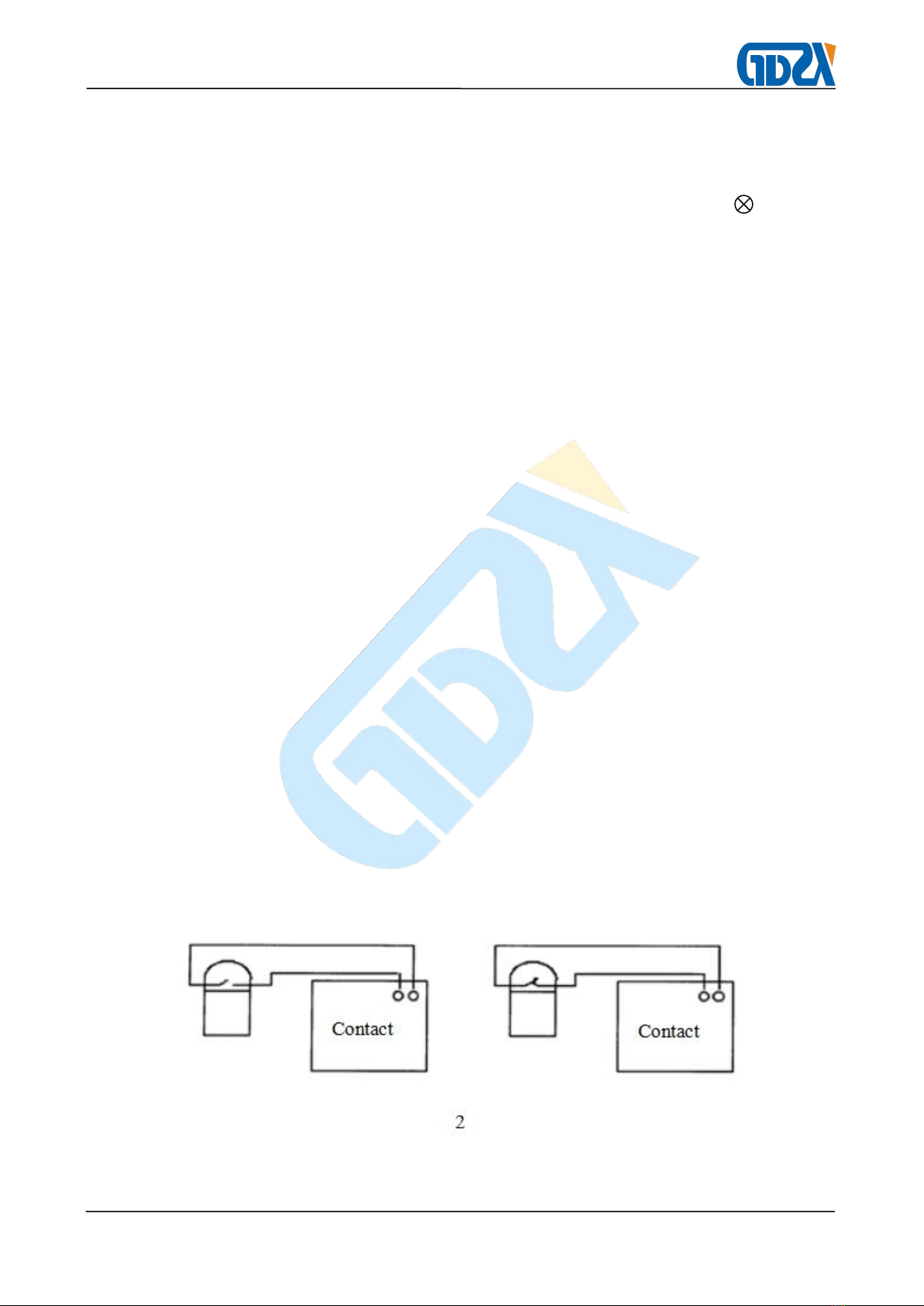
2. Overrange, underrange: test various kinds of relay starting value, return value,
return factor and contact operating time ( including voltage current relay)
Overrange indicates relay with contact closing as operation value, underrange

- 6 -
indicates relay with contact opening as operation value
Relay operation value, return value and return factor measurement:
Regulate output power according to point 4, select T3 to ,push
synchronous switch, rotate slowly T4 Knob to relay operation, when indicator
light is from off to on state, the current X1 is displayed as operation value.
Continue to regulate T4 to relay rated value, then turn T4 to relay return, when
the indicator light turns off, the X1 value is return value. Return value divided by
operation value then multiply by 100% to get return factor.
Relay time measurement
Regulate output power according to point 4, turn T3 to relay contact state,
push synchronous switch, rotate slowly T4 Knob to relay rated value. Relay time
can be tested via synchronous switch ( display value of 2). Note that the
Millisecond meter should be zero cleared and reclosing switch should be on
before the measurement.
synchronous switch and contact state relationship as following:
ⅠⅢ state, synchronous switch from off to on
ⅡⅣstate, synchronous switch from on to off
Contact wiring as following:
3. Time relay measurement method is same as above

- 7 -
4. Reclosing(DH—3 reclosing as example):
DH—3type reclosing reply operation as below
Connect wire by graph3, connect 3, 4 with J5 black column ( negative), connect
17 with J5 red column (positive)
Note: when use ZJ3 contact to stop millisecond contact, remember to cut off the
connection between ZJ3 to 1 to separate ZJ3 contact. Turn T1 to DC20A, switch
on power and turn T4 to relay rated current value, then switch off power, turn T2
to relay rated voltage value. Turn T3 to I position (that’s relay ZJ3 contact state).
Switch on power, push setting value button, reset millisecond after charging for
15~25 seconds ( the charging time can be read from millisecond meter). Push
“reclosing” button to measure reclosing time. X2 display value is reclosing time
of the reclosing relay.
Intermediate relay

- 8 -
See graph(a), the measurement of operation value, return value, operation time
and return time is same as overrange, underrange relay
Graph(b)to current hold relay. Firstly turn T2 to relay rated voltage value,
switch on power, push set button, to make relay voltage coil joined into rated
voltage value. After relay operation, turn T4 to make J1 current same as rated
current value, then cut off voltage, regulate protection coil current (T4), the
minimum hold current of the relay is the minimum hold value. Operation time and
return time test refer to point5(2).
Differential relay (BCH—1type as example)
Item 4、9、10 test can be done without external device. Item 6 test can be done
when match with external voltage regulator and current generator. Others not
within the test scope of this instrument
1) Executive component operation voltage, operation current and return current
test, wire connection as following:

- 9 -
Cut off the link between 10 and 11 terminal. Operate exactly like that for current
relay to test operation current and return current, then step up AC current to the
tested operation current value, record the present voltage, universal meter can
be used to test the voltage between the two ends of J1
No brake Starting ampere-turns test
It is not normal inspection item. Put in all the working winding 20 circuits,
connect the short-circuit of 10 and 11, input AC current from 3 and 8, input
contact operation signal from 5, 7 contact end, test like that for current relay.
The braking performance test
When make periodic inspection, just test Φ=0°and Action ampere-turns value when
Brake ampere-turns is 280

- 10 -
Connect like above graph. Cut off the link between (4) and (6), the action loop take
39 turns, the brake circuit takes 14 turns, the regulator (minimum capacity 5KVA)
and the instrument uses the same 220V power supply, adjust the brake Current to
the required ampere turns, according to the AC relay to make the action current. If
the action ampoule is completely wrong, it is possible that the phase angle of the
braking current and the operating current is 180 ° and the braking current is
reversed. If the instrument uses a phase in the three-phase, the regulator uses the
other phase, and the phase angle of 60 ° can be obtained by changing the phase
difference and booster positive and negative connection. If externally connect phase
shifter, can get 0 ~ 360 ° phase angle.
2) The whole group of volt-ampere characteristics test, according to the following
diagram wiring:
Put AC current on winding (3), (8), read voltage by a multi-meter from (9), (10),
select 1 to the AC current gear, step up current to the required turns number, read
voltage value of the executive component terminal when turns is 1 times, 2 times, 5
times.
Ampere-turn test under setting position is the same as that of the current relay
Ⅵ、Matters Need Attention
1. For safety reasons, do not turn on the power switch when the instrument and the
relay are connected. Check that the wiring is correct and then turn on the power
switch.
2. For the accuracy of the instrument, please preheat 5 to 10 minutes before the test.
3. When measuring the contact action time, the millisecond meter should be cleared
after adding the rating.
4. When the instrument is not working properly, please check the various insurance

- 11 -
seats, if damaged, replace the same type can get back to normal. Other non-fuse
issues do not repair yourselves but contact with us
5. The output power cannot be short-circuited, the contact terminal cannot be
short-circuited with the output power, so as not to damage the instrument.
6. After the test is completed, please turn off the instrument before removing the
wiring.
7. Before using the instrument, please read the instruction manual carefully.
Ⅶ、Packing list
1. The main machine 1pcs
2. Power line 1thread
3. Testing line 1set
4. Fuse(6/4A) 4pcs respectively
5. Manual 1 copy
6. Inspection Report 1copy
7. warranty card 1copy
Ⅷ、Maintenance and Repair
Products should be placed in a ventilated, cool, dry, clean place for
preservation, pay attention to moisture and gas corrosion. One year free warranty,
three years warranty, life-long maintenance.
Table of contents
Other GDZX Test Equipment manuals