GDZX ZXMD-2001 User manual

ZXMD-2001 Full Automatic
SF6 Density Relay Calibrator

1
Contents
1、Product overview................................................................2
2、Performance characteristics.............................................3
3、Technical indicators........................................................... 4
4、Panel structure....................................................................5
5、How to use...........................................................................5
6、Function description...........................................................8
7、End of work....................................................................... 20
8、Precautions....................................................................... 20
9、Custody and transportation............................................21
10、After sales service......................................................... 21
11、List of accessories......................................................... 22
Appendix 1Packing diagram of SF6 density relay transition connector
.................................................................................................... 23
Appendix II schematic diagram of cylinder inflation connection 24

2
1、Product overview
Automatic SF6 density relay calibrator is an intelligent SF6 density relay
calibrator. The instrument adopts high-precision pressure sensor and
high-speed A / D converter, combined with 32-bit high-performance
microprocessor, which can verify the performance of various SF6 density
relays,accurately measure the pressure value at the current temperature when
the signal acts, automatically complete the conversion of standard pressure at
any ambient temperature to 20 ℃, and can print and store the test data in real
time for reference and automatic identification Don't test for faults in the
process. The product is easy to carry,easy to operate, high accuracy, strong
stability and good reliability, which embodies the characteristics of "intelligent"
instrument.
SF6 switch is a widely used high-voltage electrical appliance in power
system. The reliable operation of SF6 switch has become one of the most
concerned issues in power supply and consumption departments. SF6 gas
density relay is an important component used to monitor the change of SF6
gas density in the operation of SF6 switch. Its performancedirectly affects the
operation safety of SF6 switch. The SF6 gas density relay in operation on site
often has some problems such as inflexible action and poor contact after a
period of time due to its unusual action. Some of them will also have poor
temperature compensation performance of the density relay. When the
ambient temperature suddenlychanges, the SF6 density relay often
misoperates. Therefore, DL / T596-1996 "preventive test code for electric
equipment" stipulates that all SF6 switch users shall regularly verify the SF6
gas density relay. From the actual operation, it is very necessary to check the
SF6 density relay and pressure gauge regularly.

3
2、Performance characteristics
2.1 The product adopts 32-bit microprocessor and TI company's
high-speed signal processing chip for detection and control, with high
integration degree. Mechatronics design, high precision, good repeatability,
high reliability.
2.2 Equipped with a large screen Chinese LCD screen and a rotating mouse
(one button flying shuttle) human-machine interface, the operation is simple,
the interface is beautiful, all parameters and status are clear at a glance.
2.3 Equipped with a large screen Chinese LCD screen and a rotating mouse
(one button flying shuttle) human-machine interface, the operation is simple,
the interface is beautiful, all parameters and status are clear at a glance.
2.4 Automatic pressure measurement and 20 ℃value conversion are
completed, thus dynamic automatic compensation between pressure and
temperature is completed. It also shows the pressure under the measured
ambient temperature,the pressure under the ambient temperature at 20 ℃and
the ambient temperature. The problem of field calibration of SF6 gas density
relay is solved thoroughly.
2.5 All the testing process is automatically completed by the instrument without
manual intervention, which avoids the tedious manual gas path adjustment
operation.
2.6 All metal quick connector is adopted to effectively avoid the locking
phenomenon of plastic connector in low temperature environment.
2.7 The test results are printed in Chinese character report form, and the test
results are analyzed intelligently.
2.8 It can store 50 groups of test results at the same time, and has the function
of power-off data protection. It can query and print the previous test results at
any time.

4
2.9 In the calibration process, constant temperature chamber is not required,
and SF6 gas density relay and pressure gauge can be calibrated within any
effective temperature range.
2.10 Equipped with a variety of models of transition joints, most models of
switch density relay can be field verified without disassembly.
2.11 In the calibration process, the gas consumption is very little, SF6 gas is
not wasted, the test cost is low, and there is no pollution to the environment.
2.12 It has the function of modifying the system clock online.
2.13 It has the function of modifying system pressure on line and can be
corrected on site.
2.14 The core components are imported components with reliable
performance.
2.15 It can test one set of alarm signals and two sets of locking signals at the
same time.
2.16 This product is a portable tool, easy to use and reliable, is the best choice
for SF6 density relay calibration.
3、Technical indicators
3.1 Power: AC220V、50Hz
3.2 Power consumption: 50W
3.3 Instrument accuracy: 0.2 Class
3.4 Pressure resolution: 0.001MPa
3.5 Pressure calibration range: 0~1MPa
3.6 Temperature resolution: 0.1°C
3.7 Environmental scope: -20℃~80℃
3.8 Ambient humidity: £90%RH
3.9 Communication mode: USB 2.0
3.10 Calibration object: single alarm, single latch, single alarm and single latch,
single alarm and double latch

5
3.11 Display mode: 320 × 240 LCD
3.12 Operation mode: rotate mouse input
3.13 Printer: high speed micro printer
3.14 Printing method: English printing
3.15 Storage capacity: store 50 sets of test results
3.16 Dimensions: host: 365×300×220(mm3)
Accessory: 400×370×200(mm3)
3.17 SF6 gas density display mode: pressure under the tested environment,
equivalent pressure at 20 ℃.
3.18 Weight:8kg
4、Panel structure
1.inlet
2.Calibration port
3.Pressure gauge
4.Temperature sensor
5.Power supply
6.power switch
7.USB
8.printer
9.LCD
10.RESET
11.MOUSE
12.release button
13.Signal interface
14.Outlet
5、How to use
5.1 LCD description
The instrument adopts 320 × 240 high-resolution gray backlit LCD, which can
display clearly even in strong sunlight. Parameter setting and test results are

6
displayed on LCD screen. All Chinese operation interface, clear graphics,
beautiful, easy to operate.
5.2 Mouse instructions
The function of rotating the mouse is similar to the mouse used on the
computer. It has three operations: "left", "right", "click to select". Through these
three kinds of operations of the mouse, the functions of moving cursor, data
input and operation selection can be realized.
Move cursor: move the cursor by turning the mouse left or right, move the
cursor to the option to be selected, and click the knob to select this item.
Data input: when the data needs to be modified or input, move the cursor
to the option to modify the data, click the mouse to enter the data modification
operation (the cursor is reduced to the modified position), left or right mouse to
increase or decrease the position, click the mouse to confirm the modification
of the position. Rotate the mouse to enterthe next modification. After the bit by
bit modification, the cursor increases to full cursor, that is, to exit the
modification of data. At this time, you can move the cursor away by rotating the
mouse.
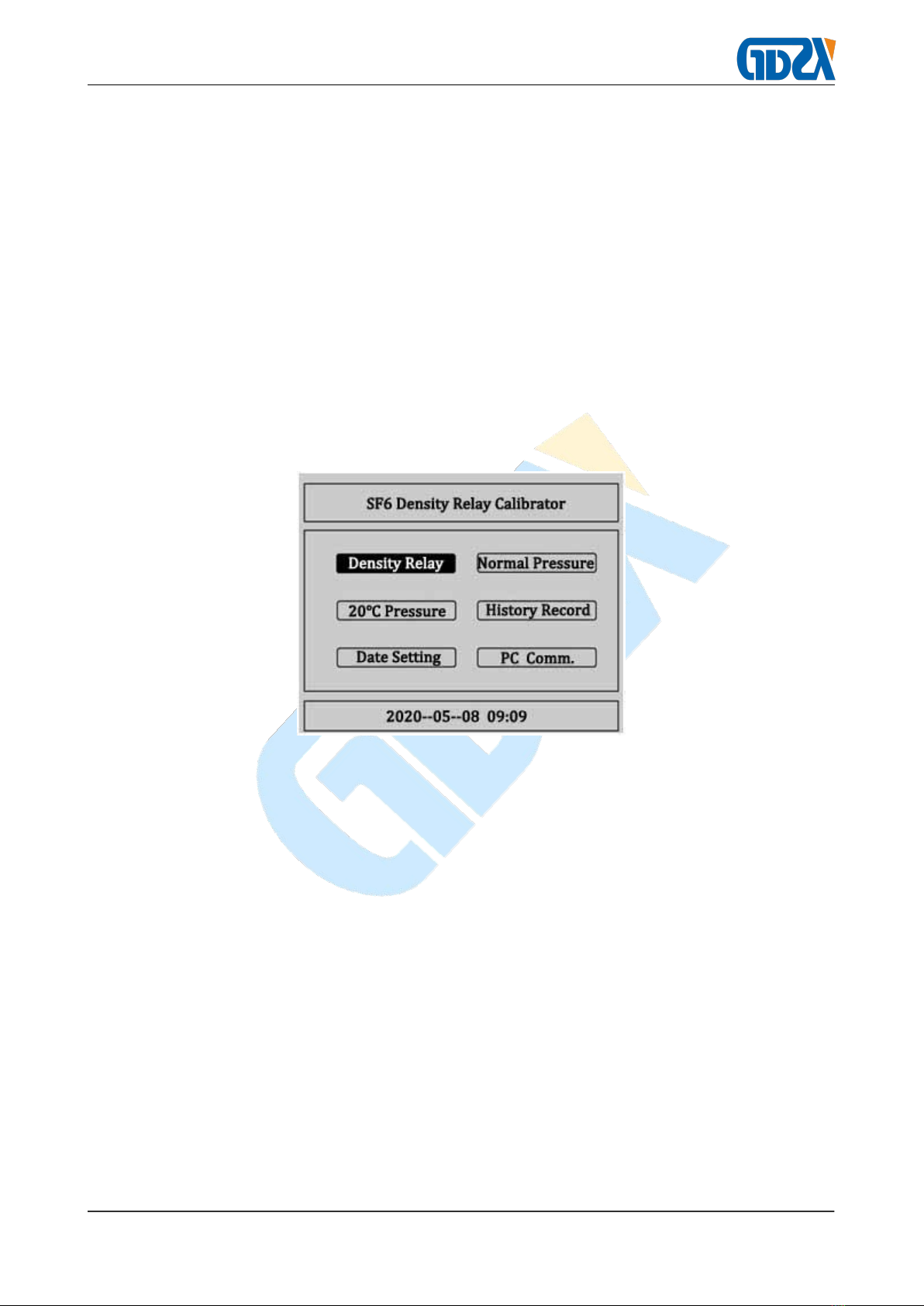
5.3 Instrument instructions
When verifying the SF6 density relay on site, please use the accessories
configured by the instrument to connect the gas circuit and the circuit as shown
in Figure 1, The air inlet pipe is connected with the measuring port of the
instrument and the gas cylinder,and the air outlet pipe is connected with the air
outlet (the non-toxic and harmless compressed gas such as air and nitrogen
can be directly discharged into the air without connecting the air outlet),the
measuring pipe is connected with the measuring port of the instrument and
connected with the SF6 density relay to be tested through the transition joint
(see Appendix 1-14 for the transition joint), and the six core test line is
connected with the instrument Corresponding test points on the wiring cabinet.

7
Figure 1
According to the test target, connect one end of the equipped six core test
line with the aviation plug-in signal port on the instrument panel, and connect
the end with the alligator clamp with the signal socket on the junction cabinet of
the density relay according to the test signal. The unused alligator clamp shall
be idle and shall not contact with other alligator clamps. When testing a signal
(one of single alarm, single lock 1 or single lock 2), only the corresponding test
signal shall be received, and "single signal" shall be selected on the operation
interface, and the system will automatically identify.
If the pressure gauge calibration operation needs to be performed, it is
necessary to connect the pressure gauge to be calibrated with the measuring
port on the instrument panel; if the system pressure value correction operation
needs to be performed,it is necessary to connect the high-precision pressure
gauge calibrated by measurement with the measuring port on the instrument
panel as shown in Figure 2.

8
Figure 2
6、Function description
After connecting the gas circuit, you can open the valve on the gas
cylinder, turn on the power supply of the instrument, and enter the main
interface after system initialization, as shown in Figure 3, which has the
functions of " Density relay ", " Normal Pressure ", "20℃Pressure ", " History
Record ", " Date Setting ", " PC Comm.",etc. Rotate the mouse left and right,
the cursor can switch freely before each function item, select the function item,
and click Select to enter.
Figure 3
6.1 Verify SF6 density relay
Basic principle of SF6 density relay calibration: the gas pressure in the closed
vessel changes with the change of temperature, and the relative pressure value of
SF6 at 20 ℃is usually taken as the standard value. In the field calibration,the SF6
pressure value measured at a certain ambient temperature shall be converted to
the equivalent pressure value at 20 ℃, so as to judge the performance of the
density relay.
Verification of latching reply value:At the ambient temperature, when
the SF6 density relay is at zero pressure, slowly inflate the SF6 density relay at
a certain speed. When the locking relay of the SF6 density relay acts, record
the pressure value under the current ambient temperature, and convert it into

9
the equivalent pressure value at 20 ℃. The equivalent pressure value at 20 ℃
is the locking recovery value of the SF6 density relay.
Verification of alarm reply value:Continue to slowly inflate the SF6
density relay at a certain speed. When the alarm relay of the density relay acts,
record the pressure value under the current ambient temperature, and convert
it into the equivalent pressure value at 20 ℃. The equivalent pressure value at
20 ℃is the alarm reply value of the SF6 density relay.
Alarm value verification:Under the ambient temperature, when the
pressure in SF6 density relay is greater than the alarm return value, slowly
deflate at a certain speed. When the alarm relay of SF6 density relay acts,
record the pressure value under the current ambient temperature, and convert
it into the equivalent pressure value at 20 ℃. The equivalent pressure value at
20 ℃is the alarm value of SF6 density relay.
Verification of blocking value:Continue to slowly deflate the SF6
density relay at a certain speed. When the locking relay of the SF6 density
relay acts, record the pressure value under the current ambient temperature,
and convert it to the equivalent pressure value at 20 ℃. The equivalent
pressure value at 20 ℃is the locking value of the SF6 density relay.
In the main interface, select the "density relay verification" item with the
cursor, and click "select" to enter the density relay verification program, as
shown in Figure 4:

10
Figure 4
This is the parameter setting interface of SF6 density relay verification.In
this interface, four parameters can be set, such as upper limit pressure,
detection times, temperature acquisition, signal type, etc.
"Upper limit pressure" refers to the switching pressure value from air inlet to
air outlet when testing the density relay. "Click to select" will display the decile,
percentile and thousandth of the selected value in reverse order. After
selecting one position, rotate the mouse left and right to change from 0 to 9.
The setting range of pressure value is 0.001mpa to 0.999mpa, and the default
value is 0.1MPa.
"Detection times" is used to set the cycle times of inflation and deflation. Click
"select" to select between 1, 2 and 3. The default value is 1.
"Temperature mode" is used to select the temperature acquisition mode of the
system. There are two options: "system" and "input"."System" refers to the
sensor provided by the system to sense the ambient temperature; "input"
refers to the internal temperature of the density relay tested by the user with an
infrared thermometer, and then manually input.The default is system
acquisition. When the cursor moves to temperature acquisition, click Select to
switch between the system and input. When it is input, the cursor will select the
entered temperature value, and then rotate the mouse left and right to set the
temperature value.
"Signal type" is used to select the signal type for test. There are three
options, namely "single signal", "single lock" and "double lock", and "click to
select" to switch back and forth. The three options are described in detail
below.
Single signal:When selecting a single signal, only one test signal can be
connected to the instrument, and either single alarm, single lock 1 or single
lock 2 can be selected, which is determined by the physical connection and
automatically recognized by the system.

11
Single block:When single locking is selected, the system has two test
signals connected to the instrument, among which there must be a single alarm,
and either single locking 1 or single locking 2 can be selected. At this time, the
system tests two signals at the same time.
Double locking:When double locking is selected, three signals must be
connected to the system at the same time, and the system tests three signals
at the same time.
Click "OK" to enter the density relay test interface.
Click "return" to return to the previous interface.
The test interface of density relay is shown in Figure 5. There are six
groups of values on the interface, including alarm reply value, alarm value, lock
reply value 1, lock reply value 1, lock reply value 2 and lock value 2. According
to the set test times and signal type test results, they will be displayed
correspondingly. PT is the normal temperature pressure value and P20 is the
equivalent pressure value converted to 20 ℃.
Figure 5
After confirming that the external air circuit is ready, click "start", and the
system will start testing according to the previously set parameters.During the
detection process, there will be a sound of opening or closing the solenoid
valve. When the pressure is increased to the preset upper limit pressure value,
there will be a short and rapid air release sound on the vent pipe when the
pressure is reduced. The corresponding test results will be successively

12
displayed on the screen. At the same time, the status bar at the lower left
corner of the screen will prompt the detection times. The schematic diagram of
pressure increase and pressure decrease is shown in Figure 6 and Figure 7:
Figure 6
Figure 7
At this time, click "stop" to close the air valve and stop detection. If there is
no value display when stopping, click "start" to continue detection. Otherwise,
deflate first and then click "start".If there is a problem in the detection, the
system will display "device failure". At this time, the user should check whether
the connection of the line and the air circuit and the selection of "signal type"
are correct.After the test is completed, the status bar will show the test
completed, as shown in Figure 8.

13
Figure 8
Figure 8 shows the test results of three times, "signal type" is double
locking. Click "start" to clear the displayed value and detect again. Click "save"
and "print" to save and print the test results.Click "return" to return to the
density relay parameter setting interface.
1. Calibration of normal temperature pressure gauge
On the main interface, select "normal temperature pressure gauge
calibration" and click "select" to enter the normal temperature pressure gauge
calibration program, as shown in Figure 9.
Figure 9 is the parameter setting interface of normal temperature pressure
gauge calibration. Two parameters, temperature acquisition and pressure
target value, can be set by operating the rotating mouse.
Figure 9
The setting of "temperature acquisition" is the same as the setting in
"density relay verification". The "pressure target value" is the preset pressure

14
test point, which can be set up to four groups at most. When setting, it should
be set from small to large in order. If there is a mistake in setting, click "OK" and
the following prompt will appear, as shown in Figure 10:
Figure 10
After setting the pressure target value correctly, click "OK" to enter the
normal temperature pressure gauge calibration interface, and click "return" to
enter the main interface.
Figure 11
Figure 11 is the test interface for verification of normal temperature
pressure gauge. If several groups of test points are preset in the parameter
setting interface, several groups of default 0.000 values will appear in columns
1, 2, 3 and 4 of the interface (Figure 11 preset three groups of test points, the
first group is 0.2MPa)."Start" refers to automatic inflation and pressure rise to
the preset point, "micro charging" and "micro discharging" refers to manual
inflation and pressure rise, "input" refers to manual input of the displayed value

15
of the pressure gauge to be tested, "confirm" refers to the completion of a
group of test points, calculation and display of the error value, which can be
saved and printed after the completion of the test.
Click "start" to start detection. When the current value Pt in the first
column will rise to the preset value of the first set of test points 0.200mpa, it will
stop as shown in Figure 12. In the process of inflation, the status bar will
prompt "the first test". When the preset pressure value is reached, it will display
"detection completed".
Figure 12
Move the cursor to "input" in Figure 12, and click the "select" cursor to
move to the input value in the first column, as shown in Figure 13:
Figure 13
Rotate the mouse left and right to modify the value, input the displayed value of
the pressure gauge to be tested, then "click the selected" cursor to return to
"input", click "OK" to complete the first test, as shown in Figure 14:

16
Figure 14
Click "start" to start the second test. The operation process is the same as
the first test. The result after the completion of the three preset tests is shown in
Figure 15.
Figure 15
At this time, you can click "save" and "print" test records, and click "return"
to return to the test interface.
2. Calibration of 20 degree pressure gauge
On the main interface, select "20 degree pressure gauge calibration" and
click "select" to enter the 20 degree pressure gauge calibration program.The
calibration process of 20 degree pressure gauge is exactly the same as that of
normal temperature pressure gauge, but there are some differences on the
interface.
20The parameter setting interface of degree pressure gauge calibration is
the same as that of normal temperature pressure gauge, but the title of the

17
interface is 20 degree pressure gauge calibration. The test interface shows that
the test result is different from that of normal temperature pressure gauge. The
equivalent pressure value at 20 ℃is also displayed on the current value item,
as shown in Figure 16.
Figure 16
3. Browsing historical data
On the main interface, select "historical data browsing" and click "select"
to enter the historical data browsing interface, as shown in Figure 17.
Figure 17
Select "density relay verification test record" and click to enter the
interface shown in Figure 18.

18
Figure 18
Rotate left and right to select the number of groups, and then "click to
select" to enter figure 19.
Figure 19
In this interface, you can select to view, delete and print historical data by
turning the mouse left and right. Click "▲▼" to return to figure 18, click "return"
to return to figure 17, and click "view" to enter Figure 20.
Figure 20

19
This interface is for detailed historical measurement data. Click "print" to print
the current historical data, and click "return" to return to figure 18.
In Figure 17, you can select to view the calibration record of normal
temperature pressure gauge and 20 readings of pressure gauge. The interface
and operation process are the same as the calibration history of density relay.
4. System clock adjustment
In the main interface, select "system clock adjustment" with the cursor,
and click "select" to enter the system clock setting program, as shown in Figure
21:
Figure 21
The system time can be set in this interface, and the left and right mouse
cursors can move on the numbers of mm / DD / yyyy. After clicking "select", the
left and right mouse can be rotated to modify the numbers, set the time, click
"OK" to set the time successfully, and click "Cancel" to return to the main
interface.
5. Computer communication
Select the "computer communication" item in the main interface and click
"select" to enter the computer communication interface, as shown in Figure 22:
Table of contents
Other GDZX Test Equipment manuals