GDZX ZXR-40A User manual

ZXR-40A Transformer
Winding Resistance Tester

ZXR-40A
- 1 -
CONTENT
1. GENERAL........................................................................................................ 2
2. PERFORMANCE INDEX.............................................................................. 3
3. PANEL DESCRIPTION................................................................................. 3
4. TESTING AND OPERATING METHOD....................................................4
5. PRECAUTIONS.............................................................................................10
6. TROUBLESHOOTING.................................................................................10
7. TRANSPORTATION AND STORAGE...................................................... 10
8. UNPACKING AND INSPECTION............................................................. 11
9. OTHERS......................................................................................................... 11

ZXR-40A
- 2 -
Thank you very much for selecting our products!
For your better use of this instrument, you are kindly requested to read
this manual carefully before you use it, so as to understand its major
performances and operation method.
Caution:①It is not allowed to remove the wiring and directly switch off
the power supply during the measurement.
②For the no-load voltage regulating transformer, it is not
allowed to switch the tapping switch during the
measurement.
③In case of a sudden power failure during the measurement,
this instrument can discharge automatically. Please do not
remove the wiring immediately. Wait for at least 30 seconds
before the connection can be removed.
④The three-phase measurement applies to the windings of YN
connection. For the windings of yn connection, since
difference exists between the three-phase and single-phase
measurement results due to the effect of the resistance of the
copper bus connected, the single-phase measurement is
recommended.
⑤Caution: The three-phase measurement result doses not
include the resistance value of the neutral lead. Therefore, it
is suggested to at least verify one data using the single-phase
testing method for each phase after completing the
measurement of three-phase resistance value, so as to
determine if the neutral lead is normal.
1. General
This fast DC resistance tester (hereinafter referred to as DC resistance tester) is the product of the
latest generation for measuring the DC resistance of transformer and is optimally designed for
measuring the DC resistance of the three-phase winding of the large-capacity transformer. It can
measure the DC resistance of the three-phase winding at the same time. In case of the on-load
voltage regulating transformer, it is not required to discharge but to directly adjust the tapping
switch. The measurement time is one third of the traditional single-phase measurement, greatly
shortening the working time and labor intensity. As the DC resistor tester is provided with
large-screen LCD and the graphical interfaces, the operation is visual, clear and easy. Besides, it

ZXR-40A
- 3 -
is provided with panel type printer and large-capacity non-volatile memory, so the measurement
results can be stored and printed out easily. With good stability in data testing, speediness and
perfect repeatability, it is the best choice for the on-site measurement of DC resistance of
transformer
2. Performance Index
Testing current
Single phase: 1A 5A 10A 20A 40A
Three phase: 1A 5A 10A 20A
Measurement
scope
Single phase: 1A 10 mΩ~20Ω 5A 1 mΩ~4Ω
10A 1 mΩ~2Ω 20A 1 mΩ~1Ω
40A 1 mΩ~0.5Ω
Three-phase: 1A 10 mΩ~6Ω (each phase) 5A 1 mΩ~1Ω (each phase )
10A 1 mΩ~0.6Ω (each phase )
20A 1 mΩ~0.3Ω (each phase )
Measurement
accuracy
±0.2% (Full span ) ± 2 words
Maximum
resolution
0.1μΩ
Data storage
capacity
150 groups
Power supply
AC 220V±22V, 50Hz±2 Hz
Working
environment
Ambient temperature: 0°~40° Relative humidity :≤80%
3. Panel Description
The panel of DC resistance tester is shown in the figure below:

ZXR-40A
- 4 -
①Ia Ib Ic: The dc current output. In case of single phase or two-phase measurement, Ia
and Ib are current output.
②Ua Ub Uc Uo: The input of measuring voltage. In case of single-phase measurement,
Ua and Ub are voltage input. In case of two-phase measurement, Ua and Ub are the voltage
input of the first channel; Uc and Uo are the input of the second channel.
3Panel printer: Prints the output measurement results.
4LCD: displays the measurement results and operation prompting information, with the
function definition of the five multi-function key-presses under the current state given in
the key definition zone on the right, as shown in the figure below :
2007.01.01
Set
Measurement mode: three phase
Measuring current: 20 A
View
Wiring Diagram
Mode
Current
Measure
14:02:51
5: Contrast regulation of LCD
6Power socket: the power input of the complete unit, with built-in fuse tube. The fuse
tube is 10A/250V.
7Earthing pole: The earthing pole on the enclosure of the complete unit. Make sure that it is
reliably grounded during measurement.
4. Testing and Operating Method
1Connect with the power source and earth wire, switch on the power supply to enter into
the initial interface, as shown in the figure below:

ZXR-40A
- 5 -
2007.01.01
Set
Measurement method: Three phase
Testing current: 20 A
View
Wiring Diagram
Mode
Current
Measure
14:02:51
“Set” key-press: Set the current date and time.
“View” key-press: View the data stored, including measurement results, testing date, tapping
number and etc.
“Mode” key-press: Sets the measurement mode, including “Single Phase”, “Two-phase” and
“Three-phase”, besides, corresponding schematic wiring diagram will be
displayed in the zone of “Schematic Wiring Diagram” as the reference for
actual wiring.
“Current” key-press: Sets the size of testing current. In case of the single-phase or two- phase
measurement, the current 1A, 5A, 10A and 20A can be selected. You may
select suitable measuring current by referring to the related parameters
listed in the technical indicators as the reference.
“Measure” key-press: After the testing wire is connected and the measuring current is selected,
press “Measure” key-press to start the test.
2Single-phase measurement:
The wiring method is shown in the figure below (Taking the measurement as of RAB an
example):

ZXR-40A
- 6 -
After the winding under test is wired and the suitable measuring current is selected, press the
“Measure” key-press to allow the tester to enter into its measuring state and to start to supply
power to the winding, and then it enters into the interface as follows:
2007.01.01
Tap
R
0. 0 A
Store
The battery is charging, please wait a moment!
Current tap: 01
Print
Re-test
Exit
14:02:51
At this time, the current of the winding starts to increase. If the charging progress strip and the
current display value stand still for a long time, it indicates that the value of the resistance value
to be measured is probably beyond the measuring scope of the current, so it is not able to reach
its set value. At this time, press “Exit” key-press to return and re-select the current and retry.
When the set value is reached, it becomes constant. Then, enter into the next interface.

ZXR-40A
- 7 -
2007.01.01
Tap
R
351.2mΩ
Store
Current tap: 0 1
Print
Re-test
Exit
14:02:51
Now, the dc resistance tester starts to display the resistance value of the winding under test and
such value gradually becomes stable. At this time, press the Tap button to adjust and set the
current tap value or winding name so as to mark the measurement result. After the Tap button is
pressed down, the multi-functional key on the right becomes “▲”“▼”“ ”“OK” and
“Cancel”, and the tap setting dialogue box is ejected. After setting, press “OK” button to save it
and press “Cancel” button to modify it. Then, press “Store” and “Print” button to save or print
the measurement result. In case of any doubt about the data, press “Retest” button to carry out
the measurement and calculation again.
When measuring the on-load voltage changing transformer, after the testing data of one tapping
position becomes stable, the on-load tapping switch may be switched to the next tapping position,
without discharging to conduct the measurement over again. At this time, the resistance value of
the winding will change gradually until it becomes stable. You may also press “Re-test” button to
quickly refresh the data. Repeat the above-mentioned procedure until all the tapping tests are
completed.
③Three-phase measurement:
The three-phase measurement applies to the windings of YN star connection with neutral lead.
For the windings of yn connection, since difference exists between the three-phase and
single-phase measurement results due to the effect of copper bus connected, single-phase

ZXR-40A
- 8 -
measurement is recommended.
The three-phase wiring is shown in the figure below:
After the winding under test is wired and the suitable measuring current is selected, press the
“Measure” key-press to allow the tester to enter into its measuring state and to start to supply
power to the winding, and then it enters into the interface as follows:
2007.01.01
Tap
A
0 . 0 A
B
0 . 0 A
Store
C
0 . 0 A
The battery is charging, please wait a moment !
Current tap: 0 1
Print
Re-test
Exit
14:02:51
At this time, the current of the winding starts to increase. If the charging progress strip and the
current display value stand still for a long time, it indicates that the value of the resistance value
to be measured is probably beyond the measuring scope of the current, so it is not able to reach
its set value. At this time, press “Exit” key-press to return and re-select the current and retry.
When the set value is reached, it becomes constant. Then, enter into the next interface.
Yellow
Green
Red
Black

ZXR-40A
- 9 -
2007.01.01
Tap
A
351.2mΩ
B
350.6mΩ
Store
C
351.6mΩ
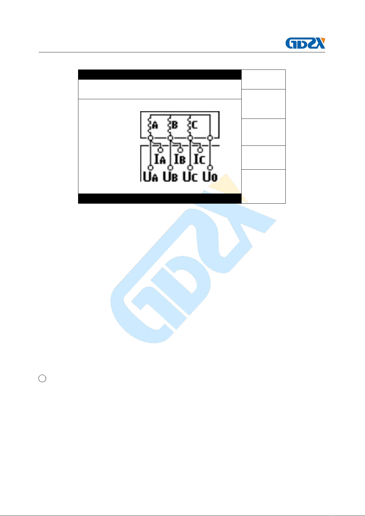
Imbalance rate: 00.28 %
Current tap : 0 1
Print
Re-test
Exit
14:02:51
Now, the dc resistance tester starts to display the resistance value of each phase. With the
resistance value of each phase becoming stable, the imbalance rate will gradually decrease.
Under such state, the “Tap” button may be pressed to adjust and set the current tap value or
winding name so as to mark the measurement result. After the “Tap” button is pressed down, the
multi-functional key on the right becomes “▲”“▼”“ ”“OK” and “Cancel”, and the tap
setting dialogue box is ejected. After setting, press the “OK” button to save it and press the
“Cancel” button to modify it. Then, press “Store” and “Print” button to save or print the
measurement results. In case of any doubt about the data, press “Retest” button to carry out the
measurement and calculation again. The maximum display scope of the imbalance rate is 50%. If
such scope is exceeded, only “50%” will be display.
When measuring the on-load voltage changing transformer, after the testing data of one tapping
position becomes stable, the on-load tapping switch may be switched to the next tapping position,
without discharging to conduct the measurement over again. At this time, the resistance value
and imbalance rate of each phase will change gradually until they become stable. You may also
press “Re-test” button to quickly refresh the data. Repeat the above-mentioned procedure until
all the tapping tests are completed.
Upon the completion of the measurement, press the “Exit” key to end the measurement. At
this time, the DC resistance tester starts to discharge and the display gives corresponding
discharge indication and the buzzer rings. After the discharge is completed and the tester

ZXR-40A
- 10 -
returns to the initial interface, the measurement wiring may be removed.
5. Precautions
1When measuring the no-load voltage changing transformer, be sure to exit from the
discharge before switching the tapping switch. Do not switch the tapping switch before the
discharge is completed according to the discharge indication.
2Do not remove the wiring during the measurement.
3If the charging progress strip and the current display value stand still for a long time, it
indicates that the value of the resistance value to be measured is probably beyond the
measuring scope of the current, so it is not able to reach its set value. At this time, press the
“Exit” button to return and reselect the current to retry.
4When replacing the fuse tube and the fittings, please use the same model as this instrument.
6. Troubleshooting
Fault phenomenon
Cause analysis
Solution
Remarks
There is no display
after switching on.
1) The power supply
is not switched on.
Switch on the
power supply
Replace with the
fuse tube of the
same model. Do not
substitute it with the
fuse tubes of other
models.
2) The 10A fuse tube
of the instrument is
not properly fitted or
the circuit is open.
Fit or replace the
fuse tube
There is no current
output
1) The equipment to
be tested is
open-circuited
Check the
equipment and
eliminate the faults.
2) The test circuit is
open-circuited.
Check the test
circuit and
eliminate the
open-circuit fault.
7. Transportation and Storage
■ Transportation
When transporting the equipment, it is suggested using the instrument packing wood boxes and
damping materials of our company to avoid any unnecessary damage and loss during the
transportation.
Do not stack the equipment if it is not transported in a wood box. If the instrument packing box

ZXR-40A
- 11 -
of our company is used, the maximum permissible stacking layers are two layers.
The equipment shall be transported with the instrument panel facing upward.
■ Storage
The equipment shall be stored in the dry, dust-free and well-ventilated room without corrosive
gas. Do not stack the equipment if it is not packed in the wood box.
The equipment shall be stored with its panel facing upward. Besides, damproof materials shall be
provided at its bottom to protect it from dampness.
8. Unpacking and Inspection
■ Precautions for unpacking
Before unpacking, make sure that the arrow on the package of the equipment is upward. When
unpacking, do not knock it by force, otherwise the equipment will be damaged. Unpack and take
out the equipment. To protection the environment, keep the equipment package and damping
materials so that you can use them for future transportation and storage.
■ Inspection content
Take out the equipment and check and count the equipment and fittings against the packing list.
In case of any shortage, please make contact with our company. We will give serve you as soon
as possible.
9. Others
The warranty period for the whole set of this product is one year and “Three-guarantees” (repair,
return and exchange guarantees) is implemented. Maintenance service can be provided
throughout its service life. For any quality problem of the equipment within the warranty period,
free maintenance will be provided. For the damages due to the improper operation or
carelessness of the user, services will be provided at favorable prices.
We are looking forward to your precious suggestions about our product. If the address and
contact information of your company are changed, please keep us informed so that we can serve
you in good time.
Table of contents
Other GDZX Test Equipment manuals