LeakSmart PROTECT User manual

PROTECT
by LeakSmart
Flow Meter Shut-o Valve System
User Manual

2 3
Installation Overview:
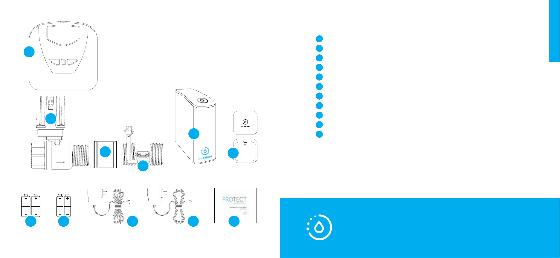
In the Box.................................................................................................................................. 4
Setup Requirements.............................................................................................................6
Important Installation Information................................................................................7
Section I:
LeakSmart Hub 3.0 Pre-Installation Customer Setup
Requirements...........................................................................................................................9
Section II:
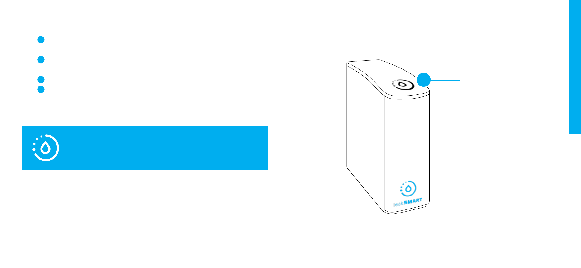
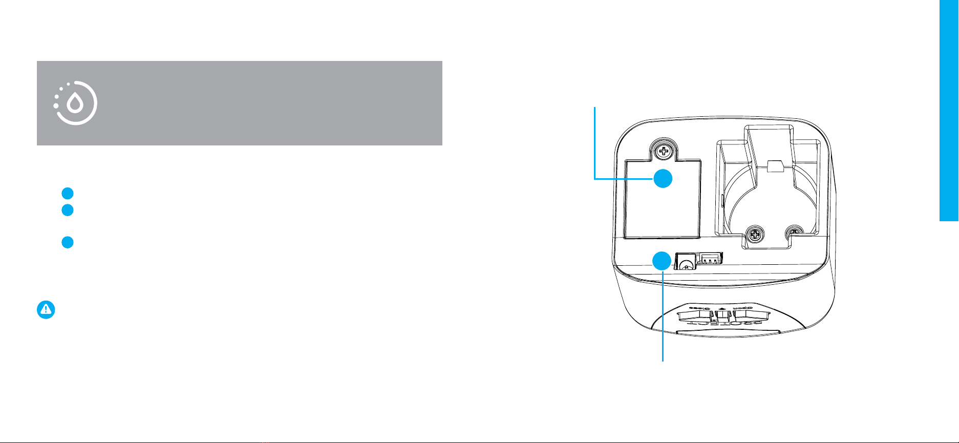
LeakSmart Hub 3.0 Installation.....................................................................................10
Performing a Factory Reset............................................................................................13
Connect the Hub to the Home Wi-Fi Network.....................................................15
Protect by LeakSmart Setup..........................................................................................16
Pair the Protect by LeakSmart to the Hub 3.0.......................................................18
Test Local and Remote Control of the Valve Control Head..........................20
Table of Contents Table of Contents
Section III:
Protect by LeakSmart Flow Meter Shut-O Valve Installation ...................22
Pre-Installation Assembly................................................................................................22
Installation Assembly.........................................................................................................24
Protect by LeakSmart Validation................................................................................30
Section IV:
Sensor Setup and Operation........................................................................................32
Place and Test Sensors....................................................................................................36
Alert Setup.............................................................................................................................40
Adding Alert Contacts.....................................................................................................40
Test Leak Simulation..........................................................................................................41
Clearing Test Leaks............................................................................................................41
Test Flow Analytics.............................................................................................................42

4 5
Valve Control Head
Shut-o Valve
Coupling
Flow Meter
Hub 3.0
Sensors (3)
AA Batteries (4)
AAA Batteries (9)
Valve Control Head AC Power Adapter (18’ reach)
Hub AC Power Adapter (6’ reach)
Setup Manual
Hub 3.0 Lithium Battery (Pre-installed)
In the Box:
Not Pictured:
1
3
5
7
2
4
6
8
9
10
11
Note: Additional ttings may be required based on
installation requirements.
Encuentra nuestro manual en español en LeakSmart.com/support/manuals/
1
2
3
7 8 11
5
6
910
4

6 7
CAUTION:
• Do not install on re suppression systems/re sprinkler water lines.
• Never place your ngers inside the Shut-o Valve or Flow Meter.
• Do not grip the plastic motor drive for leverage when installing
the valve.
• LeakSmart recommends compliance with all local building and
safety codes when installing the Protect by LeakSmart System.
• LeakSmart Hub and Sensors are for indoor use only.
• For outdoor use of the valve, utilize the approved enclosure box
available from LeakSmart.
To set up the LeakSmart System, you need:
• Wi-Fi
• An iOS or Android phone or tablet
• A free LeakSmart account
Setup Requirements Important Installation Information
Note: LeakSmart devices in the home communicate
on a local zigbee RF network and do not require Wi-Fi
to protect your home. Wi-Fi is required for intital set
up and notications.
Professional installation recommended.
5-year LeakSmart warranty when purchased and
installed by a professional. All other purchases and
installations include a 2-year warranty.

8 9
Before installing the LeakSmart Hub 3.0, the customer needs an active
LeakSmart account to register the hub.
Download the LeakSmart app from the Apple App Store or
Google Play on your smart phone or tablet.
Open the app and tap create an account.
Follow the instructions in the app to create your account.
Create a password that:
• Is between 8-19 characters
• Has at least one number or special character
• Has at least one capital letter and one lower case letter
LeakSmart Hub 3.0 Pre-Installation Customer Setup Requirements
The homeowner’s Wi-Fi network and password are
used to activate the hub. It’s best practice to get that
information before starting the installation process.
2
3
4
5
6
7
1
Activate Account
Go to your email.
Open the email from noreply@mywateralerts.com.
Tap the activate your account link in the email.
Look for the on-screen conrmation.
Log in to your account in the LeakSmart app.
LeakSmart Hub 3.0 Pre-Installation Customer Setup Requirements
2
4
5
1
3
Note: Your email will be your LeakSmart account name.
Tap Next.
Review your information and agree to the terms of use.
Tap Submit to create your account.
After you create the account, activate and verify the account.

10 11
Place the hub in a location central to the other LeakSmart
devices.
Plug the hub 3.0 in, using the AC power adapter cord.
• The hub 3.0 cannot be registered/activated on battery
power; it must be plugged in.
• The included lithium batteries are intended to be a
backup in the event of a power outage.
LeakSmart Hub 3.0 Installation LeakSmart Hub 3.0 Installation
3
2
3a
Slide the
on/o
button to
the ON
position.
Central location:
place hub in a
location central to
other devices.
A solid red
light on top
of the hub
indicates
that it’s on.
Plug in AC adapter cord.
Slide the on/o button on the back of hub to the ON position.
• A solid red light on top of the hub indicates that it’s on.
2
13
3a
1

12 13
LeakSmart Hub 3.0 Installation
Log into the LeakSmart app with homeowner/customer
account credentials.
Tap Add Hub.
Back out of - but do not close - the LeakSmart app.
Open the phone or tablet settings.
Open Wi-Fi settings.
• The LeakSmart Hub should appear in your list of available
networks as LeakSmart-XXXX.
• The four-digit code is the last four digits of the MAC
address of LeakSmart Hub. (You can nd this number on the
battery door of the Hub).
Conrm that you have successfully connected your phone or
tablet to the LeakSmart-XXXX network.
Return to the LeakSmart app.
4
5
6
7
8
Note: If the LeakSmart Hub network does not
appear, perform a factory reset.
Use a pin (or something with a thin tip) to press
and hold the factory reset button on the back of
the LeakSmart hub for fteen-seconds.
• A purple light on top of the hub indicates that the hub is
ready for factory reset.
Turn the hub o, then back on.
The LeakSmart hub will then show up on the Wi-Fi network.
Tap LeakSmart-XXXX to join the network.
Performing a Factory Reset (If Needed)
2
3
4
1
1a
10
91a
A purple light on
top of the hub
indicates that the
factory reset is
complete.
Press and hold
the reset button to
perform a
factory reset.
1
Turn the hub
o/on. 2

14 15
Connect the LeakSmart Hub 3.0 to the Home Wi-Fi Network
Tap the name of the homeowner’s Wi-Fi network.
(network must be 2.4GHz in order to work).
Type the homeowner’s Wi-Fi password
in the password eld.
Tap Connect.
A solid blue light on top of the hub indicates that the hub is
connected to the home Wi-Fi network.
LeakSmart Hub 3.0 Installation
11
12
13
14
Note: After connecting to Wi-Fi, the hub will register
itself on the cloud and should appear in the app.
The hub’s LED
indicator will turn blue
when successfully
connected to the
home Wi-Fi network.
14

16 17
Open the LeakSmart app and tap Add Devices.
For the valve control head, use a Phillips head screwdriver to
open the battery compartment and install four AA batteries.
Connect the jack of the 9V Supply Cord to the bottom of the
valve control head. Then, plug the 9V Supply Cord into
an outlet.
CAUTION:
• Do not replace the four AA batteries with a 9V battery; this will
void the warranty.
• If the provided AC power cord isn’t long enough to reach the
outlet, be sure to replace it with a low voltage extension cord.
We recommend the LeakSmart low voltage extension cord.
Protect by LeakSmart Setup Protect by LeakSmart Setup
1
2
3
Keep the LeakSmart valve control head connected
to the shut-o valve and place it at the installation
location, so you can verify that it is within
communication range to the hub.
Power the unit:
Battery compartment: open with a Phillips
head screwdriver and install (4) AA batteries.
2
9V Supply Cord Jack: plug cord into outlet after insertion.
3

18 19
Pair the Protect by LeakSmart to the Hub 3.0 Pair the Protect by LeakSmart to the Hub 3.0
Tap Next in the LeakSmart app to initialize a three-minute
pairing mode.
• A green light on top of the hub indicates that it’s in pairing
mode.
• A blue light on top of the hub indicates that the three-
minute pairing mode has ended.
A double blue light on the valve control head indicates that it’s
ready to be paired.
Tap Next in the LeakSmart app.
Press and release the center button on the valve control head
to pair it to the hub.
When the valve control head rapidly ashes blue, or all the
lights turn o, you’ve successfully paired it to the hub.
• Verify that the valve appears in the app before moving on.
1
2
3
4
5
Note: The valve may take up to one minute to pair
and populate in the app.
Green light: pairing mode is active.
Blue light: pairing mode has ended.
Rapid blue
light/no lights:
successfully
paired.
Center button: press and
release to pair to the hub.
Double blue light:
pairing mode is active.
1
4
5
2

20 21
Press the Open button on the front of the valve control head.
• A steady green light on the front of the valve control head
indicates the valve is open.
Press the Close button on the front of the valve control head.
• A steady red light on the front of the valve control head
indicates the valve is closed.
Test the communication using the LeakSmart app.
On the home screen:
Tap the Open button.
Then tap the Close button.
Test Local and Remote Control of the Valve Control Head Test Local and Remote Control of the Valve Control Head
Green light: indicates valve
opening.
Press open
Red light: indicates valve
closing.
Press close
1a
1
2a
2
2
2a
2
1
1a
1
Manually test that Protect by LeakSmart can
communicate with the hub from the intended
install location.

22 23
Remove the valve control head from the shut-o valve. Set the
valve control head aside to avoid potential damage.
Using the included coupling, assemble the ow meter
downstream from the shut-o valve. Use pipe dope or thread
tape (not included) on the mating threads.
Pre-Installation Assembly
Valve control head:
remove from the shut-o
valve and set aside.
Flow meter coupling:
assemble downstream
from the shut-o valve.
Pipe dope/thread tape:
use on mating threads.
Direction of Flow
1
Protect by LeakSmart Flow Meter Shut-O Valve Installation
2
1
Before starting the installation process, be sure that
you have all the necessary components, ttings, and
other equipment required for installation.
2
2

24 25
Turn o the main water supply.
Locate the lowest xture and drain the main water line (turn on
the hot and cold water until no more water comes out).
Install the shut-o valve/ow meter assembly.
Position the shut-o valve/ow meter assembly.
Installation Assembly Installation Assembly
CAUTION:
• Install the valve so that the controller will rest vertically or
horizontally, NOT upside down.
• Do not solder ttings near the water meter or the Protect
by LeakSmart valve system to prevent heat from aecting
the devices.
2
4
1
3Shut-o valve/ow meter assembly:
install at least 8” downsteam of the
water main manual shut-o and
water meter.
Shut-o valve/ow meter assembly:
position so that the arrow is pointing
away from the water meter.
3
4

26 27
Installation Assembly Installation Assembly
Once you’ve installed the assembly, turn on the main
water valve.
Plug the ow meter cable into the valve control head.
With the front of the valve control head facing you,
reattach the valve control head to the shut-o valve
by sliding it over the motor housing until it clicks into
place.
• Ensure that the valve control head is rmly
engaged on the shut-o valve.
5
6
7
7
Valve control head:
reattach to the shut-o
valve by sliding on until
it clicks into place.
Flow meter cable: plug into the
valve control head.
6

28 29
Press the Open button on the front of the valve control head
to check the functionality.
• A ashing green light indicates that the valve is opening.
• A steady green light indicates that the valve is open and
water will run through the valve.
Turn o the lowest hot and cold xture and check for leaks.
Installation Assembly Installation Assembly
10
10a
10b
11
Valve control head:
press open to check
functionality.
10
10a
Green light: indicates
open/opening.
CAUTION:
• Be aware of the water hammer eect when rst opening
the valve. There may be air remaining in the plumbing
lines from cutting in the valve. Once the air is released,
your system will go back to normal pressure.

30 31
Protect by LeakSmart Operation Validation Protect by LeakSmart Operation Validation
Return to the LeakSmart app.
Tap Valve to go to the valve detail screen.
Tap Current Flow to open the Current Flow Rate detail screen.
Conrm that the ow rate is at 0 gallons/minute.
Turn on a hot and cold xture.
While the valve is open and water is running through it, conrm
that the ow rate is reporting on the Current Flow Rate screen.
Turn o the xture and leave the valve open.
1
2
3
4
5
6
7
For testing of ow meter functionality, ensure the main
water is on, xtures are closed and the valve is open.
Conrm that the ow rate is at
0 gallons/minute.
Turn on a hot and cold xture.
Turn o the xture and leave the valve open.
While the valve is open and water is running
through it, conrm that the ow rate is
reporting on the Current Flow Rate screen.

32 33
Use the Phillips head screwdriver to remove the battery
compartment door from the LeakSmart Sensor.
Install the three provided AAA batteries, but
DO NOT REPLACE THE BATTERY DOOR.
• A chirp from the sensor indicates that the batteries
have been installed.
• A ashing blue light from the sensor indicates that
it’s ready to pair.
Open the LeakSmart app on your phone or tablet.
Tap Add Devices from the home screen.
Tap Next in the LeakSmart app until you see the pairing
mode screen showing device count.
LeakSmart Sensor Setup and Operation LeakSmart Sensor Setup and Operation
Note: To complete the setup, you will need a Phillips
screwdriver, a damp cloth and a dry cloth.
1
2
3
4
5
Battery compartment: temporarily remove
door using Phillips head screwdriver.
AAA batteries: install three batteries after
temporarily removing battery door.
1
2

34 35
To pair the sensor to the hub, press the black button inside the
battery compartment of the LeakSmart Sensor one time.
• When the pairing is successful, the light on top of the sensor
will blink slowly ve times, and you’ll hear three quick beeps.
In the LeakSmart app, watch for the total device count and the
sensor count to each increase by one.
With the sensor successfully paired, replace the battery
compartment door.
To pair additional sensors, repeat steps 1-7.
Tap All My Devices are Paired.
LeakSmart Sensor Setup and Operation LeakSmart Sensor Setup and Operation
6
6a
7
8
9
10
Note: Pairing mode will last for three minutes. If
you don’t successfully pair the sensor(s) before
the three-minute pairing mode ends, you’ll have
to start over at step four.
Black button: to pair the sensor to
the hub, press this button once.
Battery compartment: replace door
once sensor is successfully paired.
Sensor: ve slow ashes from the LED
light and three quick beeps indicate
that the pairing is successful.
6
6a
8

36 37
Newly paired sensors are displayed under Untested
Sensors with a indicating that the sensor needs to be
named, tested, and placed in its intended location.
Tap on a sensor from the untested sensors list. The selected
sensor will beep to identify itself.
When you identify the beeping sensor, tap Ok, I have the
sensor in the app.
Take the sensor and a damp cloth to a location you need
to monitor for water. We recommend placing the sensor
near old pipes, toilets, washing machines, water heaters,
bathtubs, crawl spaces, utility closets, or anywhere you
want to monitor water leaks.
In the app, name the sensor to identify its location, e.g.,
masterbath toilet (the sensor name can have a maximum
of 20 characters).
Tap Add Location to initiate test mode.
Place and Test Sensors Place and Test Sensors
1
2
3
4
5
6
Tap All My Devices are Paired
in the LeakSmart app. Look for
untested sensors using .
After identifying the untested sensor,
Tap Ok, I have the sensor in the app.
Take the sensor and a damp cloth to a
location you need to monitor for water.
In the app, name the sensor to
identify it’s location. Tap Add
Location to initiate test mode.

38 39
Press and hold the damp cloth to the gold pins on the back of
the sensor to trigger a leak (it will beep).
Keeping the damp cloth on the gold pins, tap My Sensor is
Beeping in the app. Hold damp cloth until it displays success.
Remove the damp cloth and dry the gold pins.
Place the sensor at on the oor in your desired location, with
the LeakSmart logo facing up.
In the LeakSmart app, set the sensor to its mode.
• Tap Protect to have this sensor automatically shut o the
water and send alerts when it detects a leak.
• Tap Detect-Only to have this sensor only send alerts when
it detects a leak.
Tap Finish.
Follow the on-screen prompts to set up alerts (these can be set
up later in the app alerts on your phone or tablet, or you could
follow the next section of this manual to set up alerts).
Repeat steps 1-11 for any remaining sensors.
Place and Test Sensors Place and Test Sensors
Note: If success does not display, refer to the website
for additional troubleshooting tips.
8
9
10
11
11a
11b
12
13
14
Gold pins: hold damp cloth on these to trigger
a leak until “success” is displayed. Once
conrmed, remove damp cloth and dry pins.
8
7
7
Table of contents
Other LeakSmart Protection Device manuals