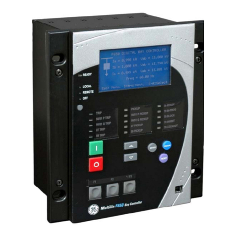
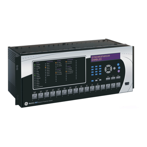
GE Multilin F650 User manual

GE Multilin
215 Anderson Avenue
L6E 1B3 Markham, ON -CANADA
T (905) 294 6222 F (905) 294 8512
Internet: www.GEMultilin.com
Firmware version: 2.20
EnerVista F650 Setup version: 2.20
Copyright © 2005 GE Multilin
F650
Digital Bay Controller
Instruction manual
GEK-106310N
GE Multilin
Avda. Pinoa, 10
48170 Zamudio SPAIN
T +34 94 485 88 00 F +34 94 485 88 45
gGE Consumer & Industrial
Multilin

GE Multilin F650 Digital Bay Controller 1
TABLE OF CONTENTS
1. GETTING STARTED 1.1 IMPORTANT PROCEDURES
1.1.1 CAUTIONS AND WARNINGS...........................................................................1-1
1.1.2 INSPECTION CHECKLIST................................................................................1-4
1.1.3 SAFETY INSTRUCTIONS.................................................................................1-6
1.2 OVERVIEW
1.2.1 INTRODUCTION TO 650 FAMILY OF RELAYS ...............................................1-7
1.2.2 HARDWARE ARCHITECTURE.........................................................................1-7
1.2.3 SOFTWARE ARCHITECTURE..........................................................................1-8
1.2.4 COMMUNICATIONS ARCHITECTURE ............................................................1-8
1.3 ENERVISTA 650 SETUP SOFTWARE
1.3.1 SYSTEM REQUIREMENTS ............................................................................1-10
1.3.2 INSTALLATION................................................................................................1-10
1.3.3 CONNECTING WITH THE UNIT.....................................................................1-15
1.3.4 COMMUNICATIONS........................................................................................1-16
2. PRODUCT DESCRIPTION 2.1 OVERVIEW
2.1.1 F650 OVERVIEW...............................................................................................2-1
2.2 SUMMARY
2.2.1 ANSI DEVICE NUMBERS AND FUNCTIONS...................................................2-2
2.3 ORDERING CODE
2.4 TECHNICAL SPECIFICATIONS
2.4.1 PROTECTION UNITS........................................................................................2-6
2.4.2 CONTROL........................................................................................................2-16
2.4.3 MONITORING..................................................................................................2-17
2.4.4 USER –PROGRAMABLE ELEMENTS............................................................2-19
2.4.5 METERING......................................................................................................2-20
2.4.6 INPUTS............................................................................................................2-21
2.4.7 REAL TIME CLOCK.........................................................................................2-23
2.4.8 OUTPUTS........................................................................................................2-23
2.4.9 CONTROL POWER SUPPLY..........................................................................2-24
2.4.10 COMMUNICATIONS........................................................................................2-24
2.4.11 ENVIRONMENTAL CHARACTERISTICS.......................................................2-25
2.4.12 PACKAGING AND WEIGHT............................................................................2-26
2.4.13 TYPE TESTS...................................................................................................2-26
2.4.14 APPROVALS ...................................................................................................2-26
2.5 EXTERNAL CONNECTIONS
3. HARDWARE 3.1 MODULE DESCRIPTION
3.2 MECHANICAL DESCRIPTION
3.2.1 MOUNTING........................................................................................................3-3
3.2.2 REAR DESCRIPTION........................................................................................3-5
3.3 WIRING
3.3.1 EXTERNAL CONNECTIONS.............................................................................3-9
3.3.2 DIGITAL INPUTS WITH TRIP CIRCUIT SUPERVISION ..................................3-9
3.3.3 CABLE/FIBER ETHERNET BOARD..................................................................3-9
3.4 OPTIC FEATURES
3.5 TRANSCEIVER OPTICAL POWER BUDGET VERSUS LINK LENGTH

2 F650 Digital Bay Controller GE Multilin
TABLE OF CONTENTS
4. HUMAN INTERFACES,
SETTINGS & ACTUAL
VALUES
4.1 ENERVISTA 650 SETUP SOFTWARE INTERFACE
4.1.1 OVERVIEW ........................................................................................................4-1
4.1.2 MAIN SCREEN...................................................................................................4-2
4.1.3 STARTING COMMUNICATION..........................................................................4-3
4.1.4 FILE MANAGEMENT .........................................................................................4-7
4.1.5 ENERVISTA 650 SETUP MENUS STRUCTURE ............................................4-12
4.1.6 FILE MENU OVERVIEW ..................................................................................4-13
4.1.7 SETTINGS MENU OVERVIEW........................................................................4-17
4.1.8 ACTUAL VALUES MENU OVERVIEW.............................................................4-26
4.1.9 OPERATIONS MENU OVERVIEW ..................................................................4-31
4.1.10 COMMUNICATION MENU OVERVIEW...........................................................4-31
4.1.11 SECURITY MENU OVERVIEW........................................................................4-32
4.1.12 VIEW MENU OVERVIEW.................................................................................4-32
4.1.13 HELP MENU OVERVIEW ................................................................................4-32
4.2 HUMAN MACHINE INTERFACE (HMI)
4.2.1 DISPLAY...........................................................................................................4-33
4.2.2 FRONT LED INDICATORS ..............................................................................4-34
4.2.3 PUSHBUTTONS..............................................................................................4-34
4.2.4 FRONT PORT AND COVER SEALING SYSTEM............................................4-35
4.2.5 TEXT MENUS...................................................................................................4-36
4.2.6 GRAPHIC DISPLAY .........................................................................................4-55
4.3 WEB SERVER
4.3.1 HOME...............................................................................................................4-64
4.3.2 SNAPSHOT EVENTS......................................................................................4-65
4.3.3 CONTROL EVENTS........................................................................................4-66
4.3.4 ALARMS..........................................................................................................4-67
4.3.5 OSCILLOGRAPHY..........................................................................................4-68
4.3.6 FAULT REPORT .............................................................................................4-69
4.3.7 DATA LOGGER................................................................................................4-70
4.3.8 METERING.......................................................................................................4-71
5. SETTINGS 5.1 OVERVIEW
5.1.1 SETTING MAIN MENU.......................................................................................5-1
5.2 PRODUCT SETUP
5.2.1 COMMUNICATION SETTINGS..........................................................................5-3
5.2.2 MODBUS USER MAP........................................................................................5-6
5.2.3 FAULT REPORT ................................................................................................5-6
5.2.4 OSCILLOGRAPHY.............................................................................................5-9
5.2.5 DATA LOGGER................................................................................................5-12
5.2.6 DEMAND .........................................................................................................5-14
5.3 SYSTEM SETUP
5.3.1 GENERAL SETTINGS......................................................................................5-20
5.3.2 FLEX CURVES.................................................................................................5-20
5.3.3 BREAKER.........................................................................................................5-22
5.3.4 SWITCHGEAR .................................................................................................5-24
5.4 PROTECTION ELEMENTS
5.4.1 CHANGE OF SETTING TABLES IN F650 ELEMENTS...................................5-25
5.4.2 INVERSE TIME CURVES CHARACTERISTICS..............................................5-29
5.4.3 PHASE CURRENT...........................................................................................5-39
5.4.4 NEUTRAL CURRENT ......................................................................................5-50
5.4.5 GROUND CURRENT .......................................................................................5-56
5.4.6 SENSITIVE GROUND CURRENT....................................................................5-59
5.4.7 NEGATIVE SEQUENCE CURRENT................................................................5-64
5.4.8 VOLTAGE ELEMENTS ....................................................................................5-65
5.4.9 POWER............................................................................................................5-70
5.5 CONTROL ELEMENTS
5.5.1 SETTING GROUP............................................................................................5-77
5.5.2 UNDERFREQUENCY ELEMENT (81U)...........................................................5-78
5.5.3 OVERFREQUENCY ELEMENT (81O).............................................................5-78
5.5.4 SYNCHRONISM CHECK ELEMENT - SYNCHROCHECK (25)......................5-79

GE Multilin F650 Digital Bay Controller 3
TABLE OF CONTENTS
5.5.5 AUTORECLOSE (79).......................................................................................5-87
5.5.6 BREAKER FAILURE ELEMENT (50BF)..........................................................5-94
5.5.7 VT FUSE FAILURE ELEMENT (VTFF) ...........................................................5-97
5.5.8 BROKEN CONDUCTOR..................................................................................5-98
5.5.9 LOCKED ROTOR ............................................................................................5-99
5.6 INPUTS/OUTPUTS
5.6.1 INPUT/OUTPUT PLACEMENT......................................................................5-101
5.6.2 CONTROL SETTINGS FOR INPUTS/OUTPUTS..........................................5-102
5.6.3 INPUTS..........................................................................................................5-104
5.6.4 OUTPUTS......................................................................................................5-106
5.6.5 CIRCUIT SUPERVISION AND CONTACT SEAL-IN CIRCUITS...................5-108
5.6.6 ANALOG BOARDS SPECIFIC SETTINGS ...................................................5-118
5.6.7 VIRTUAL INPUTS..........................................................................................5-119
5.6.8 VIRTUAL OUTPUTS......................................................................................5-119
5.7 TESTINGS
5.7.1 FORCE IO –INPUT TESTING .......................................................................5-120
5.7.2 FORCE IO –OUTPUT TESTING ...................................................................5-120
5.8 RELAY CONFIGURATION
5.8.1 OUTPUTS......................................................................................................5-121
5.8.2 LEDS..............................................................................................................5-122
5.8.3 OPERATIONS................................................................................................5-123
5.8.4 PROTECTION ELEMENTS...........................................................................5-127
5.8.5 OSCILLOGRAPHY ........................................................................................5-128
5.8.6 CONTROL EVENTS......................................................................................5-129
5.8.7 SWITCHGEAR ..............................................................................................5-131
5.8.8 HMI (HUMAN-MACHINE INTERFACE).........................................................5-132
5.9 LOGIC CONFIGURATION (PLC EDITOR)
5.9.1 INTRODUCTION............................................................................................5-135
5.9.2 THEORY OF OPERATION............................................................................5-136
5.9.3 MAIN MENU...................................................................................................5-139
5.9.4 CONFIGURATION GENERATION................................................................5-140
5.9.5 GENERATION OF LIBRARIES .....................................................................5-141
5.9.6 EXAMPLE OF APPLICATION .......................................................................5-143
6. ACTUAL VALUES 6.1 FRONT PANEL
6.1.1 LEDS..................................................................................................................6-1
6.2 STATUS
6.2.1 OPERATION BITS.............................................................................................6-2
6.2.2 BREAKER..........................................................................................................6-2
6.2.3 PROTECTION....................................................................................................6-2
6.2.4 CONTROL ELEMENTS.....................................................................................6-8
6.2.5 PROTECTION SUMMARY..............................................................................6-13
6.2.6 SNAPSHOT EVENTS SUMMARY...................................................................6-14
6.2.7 MODBUS USER MAP......................................................................................6-15
6.2.8 SWITCHGEAR STATUS..................................................................................6-16
6.2.9 CALIBRATION.................................................................................................6-17
6.2.10 FLEX CURVES ................................................................................................6-18
6.2.11 SYSTEM INFO.................................................................................................6-18
6.2.12 RECORD STATUS ..........................................................................................6-18
6.3 METERING
6.3.1 PRIMARY VALUES..........................................................................................6-22
6.3.2 SECONDARY VALUES...................................................................................6-25
6.3.3 PHASOR DIAGRAM........................................................................................6-27
6.3.4 FREQUENCY...................................................................................................6-27
6.3.5 INPUTS / OUTPUTS........................................................................................6-28
6.4 RECORDS
6.4.1 EVENT RECORDER........................................................................................6-34
6.4.2 WAVEFORM CAPTURE..................................................................................6-36
6.4.3 FAULT REPORT..............................................................................................6-37
6.4.4 DATA LOGGER...............................................................................................6-39

4 F650 Digital Bay Controller GE Multilin
TABLE OF CONTENTS
7. IEC 61850 PROTOCOL 7.1 IEC61850 GENERIC SUBSTATION STATE EVENT (GSSE)
7.1.1 REMOTE DEVICES............................................................................................7-1
7.1.2 REMOTE INPUTS ..............................................................................................7-3
7.1.3 REMOTE OUTPUTS ..........................................................................................7-4
7.2 IEC 61850 PROFILE FOR F650
7.2.1 INTRODUCTION ................................................................................................7-6
7.2.2 ACSI CONFORMANCE STATEMENT...............................................................7-6
7.2.3 LOGICAL NODES ............................................................................................7-11
7.2.4 COMMON DATA CLASS..................................................................................7-29
7.2.5 DATASETS.......................................................................................................7-44
7.2.6 MAPPINGS BETWEEN TOC CURVES IN IEC 61850 AND F650 RELAY
IMPLEMENTATION. 7-46
7.2.7 UNIDADES Y ESCALAS DE LOS DATOS ANALÓGICOS .............................7-47
8. SECURITY 8.1 ADDING USERS
8.1.1 USER RIGHTS ...................................................................................................8-1
8.2 CHANGING PASSWORDS
8.3 ENABLING SECURITY
8.4 LOGING INTO ENERVISTA 650 SETUP
9. BOOTCODE AND
FIRMWARE UPGRADE 9.1 INTRODUCTION
9.1.1 COMMUNICATION PARAMETERS...................................................................9-2
9.2 BOOT CODE UPGRADE
9.3 FIRMWARE VERSION UPGRADE
9.3.1 FIRMWARE UPGRADE .....................................................................................9-9
9.4 STEP LIST SUMMARY FOR VERSIONS 1.70 AND LATER
9.4.1 BOOT CODE UPGRADE (*).............................................................................9-12
9.4.2 FIRMWARE UPGRADE (*)...............................................................................9-12
10. COMMISSIONING 10.1 VISUAL INSPECTION
10.2 GENERAL CONSIDERATIONS ON THE POWER SUPPLY NETWORK
10.3 ISOLATION TESTS
10.4 INDICATORS
10.5 POWER SUPLY TESTING
10.6 COMMUNICATIONS
10.7 VERIFICATION OF MEASURE
10.7.1 VOLTAGES ......................................................................................................10-7
10.7.2 PHASE CURRENTS.........................................................................................10-7
10.7.3 ACTIVE, REACTIVE POWER, AND COSJ METERING..................................10-8
10.7.4 FREQUENCY...................................................................................................10-8
10.8 INPUTS AND OUTPUTS
10.8.1 DIGITAL INPUTS..............................................................................................10-9
10.8.2 CONTACT OUTPUTS....................................................................................10-10
10.8.3 CIRCUIT CONTINUITY SUPERVISION INPUTS ..........................................10-10
10.8.4 LATCHING CIRCUITS....................................................................................10-10

GE Multilin F650 Digital Bay Controller 5
TABLE OF CONTENTS
10.9 CONNECTIONS FOR TESTING PROTECTION ELEMENTS
10.10 INSTANTANEOUS OVERCURRENT (50PH, 50PL, 50N, 50G Y 50SG)
10.11 INVERSE TIME OVERCURRENT (51PH, 51PL, 51N, 51G Y 46)
10.12 DIRECTIONAL ELEMENTS (67P, 67N, 67G, 67SG)
10.12.1 67P ELEMENT...............................................................................................10-14
10.12.2 67N ELEMENT...............................................................................................10-14
10.12.3 67G ELEMENT ..............................................................................................10-15
10.12.4 67SG ELEMENT............................................................................................10-16
10.13 UNDERVOLTAGE ELEMENTS (27P, 27X)
10.13.1 27P ELEMENT...............................................................................................10-17
10.13.2 27X ELEMENT...............................................................................................10-17
10.14 OVERVOLTAGE ELEMENTS (59P, 59X, 59NH, 59NL, 47)
10.14.1 59P ELEMENT...............................................................................................10-18
10.14.2 59X ELEMENT...............................................................................................10-18
10.14.3 59NH AND 59NL ELEMENTS .......................................................................10-19
10.14.4 47 ELEMENT - NEG SEQ OV .......................................................................10-20
10.15 FREQUENCY ELEMENTS (81O/81U)
10.16 RECLOSER (79)
10.16.1 RECLOSING CYCLE.....................................................................................10-22
10.16.2 RECLOSER STATUSES ...............................................................................10-23
10.16.3 EXTERNAL RECLOSE INITIATION..............................................................10-23
10.17 THERMAL IMAGE ELEMENT (49)
11. APPLICATION EXAMPLES 11.1 EXAMPLE1: COMMUNICATION & PROTECTION SETTINGS
PROCEDURE
11.1.1 DESCRIPTION OF THE EXERCISE...............................................................11-1
11.1.2 PROCEDURE TO COMMUNICATE WITH THE RELAY.................................11-1
11.1.3 PROCEDURE TO SET THE PROTECTION FUNCTION................................11-3
11.1.4 TEST................................................................................................................11-4
11.2 EXAMPLE 2: TOC PROTECTION + RECLOSING SETTINGS
PROCEDURE
11.2.1 DESCRIPTION OF THE EXERCISE...............................................................11-5
11.2.2 PROCEDURE TO COMMUNICATE THE RELAY...........................................11-5
11.2.3 PROCEDURE TO SET THE PROTECTION FUNCTION................................11-5
11.2.4 PROCEDURE TO SET THE RECLOSER .......................................................11-6
11.2.5 PROCEDURE TO SET THE SYNCHRO CHECK ...........................................11-6
11.3 EXAMPLE Nº 3 – PROCEDURE TO SET AN OPERATION
11.3.1 DESCRIPTION OF THE EXERCISE...............................................................11-8
11.3.2 PROCEDURE .................................................................................................11-8
11.3.3 TEST..............................................................................................................11-10
12. FREQUENTLY ASKED
QUESTIONS 12.1 COMMUNICATIONS
12.2 PROTECTION
12.3 CONTROL AND HMI
12.4 RELAY CONFIGURATION
13. TROUBLESHOOTING
GUIDE

6 F650 Digital Bay Controller GE Multilin
TABLE OF CONTENTS
A. LOGIC OPERANDS
B. MODBUS PROTOCOL B.1 ACCESS TO F650 DATA
B.2 MODBUS F650
B.2.1 FUNCTIONS USED...........................................................................................B-2
B.2.2 PHYSICAL LAYER............................................................................................B-3
B.2.3 DATA LINK LAYER ...........................................................................................B-4
B.2.4 GENERIC READING.........................................................................................B-5
B.2.5 GENERIC WRITING..........................................................................................B-6
B.2.6 FUNCTION CODES .........................................................................................B-7
B.2.7 EXCEPTIONS AND ERROR RESPONDS........................................................B-8
B.3 DATA TYPE
B.4 MODBUS APPENDIX
B.4.1 DATA MANAGEMENT ....................................................................................B-10
B.4.2 WRITING SETTINGS ......................................................................................B-11
B.4.3 SNAP-SHOT EVENTS ....................................................................................B-12
B.4.4 OPERATIONS .................................................................................................B-15
B.5 OUTPUT WRITING
B.5.1 CONTROL EVENTS........................................................................................B-17
B.5.2 EVENT STRUCTURE......................................................................................B-18
B.6 EVENTS STATUS REQUEST (ALARMS)
B.6.1 CONTROL EVENTS RETRIEVAL FROM THE COMMAND LINE .................B-21
B.6.2 SERIAL COMMUNICATION............................................................................B-22
B.6.3 ETHERNET COMMUNICATION .....................................................................B-23
B.6.4 ACKNOWLEDGEMENT OF EVENTS (ALARMS)...........................................B-24
B.6.5 VIRTUAL INPUTS WRITING...........................................................................B-25
B.6.6 USER MAP......................................................................................................B-26
B.6.7 RETRIEVING OSCILOGRAPHY.....................................................................B-27
B.6.8 TIME SYNCHRONIZATION ............................................................................B-28
B.6.9 ENQUEUEING MESSAGES ..........................................................................B-29
B.6.10 TRACES AND TROUBLESHOOTING.............................................................B-30
B.6.11 MODBUS CHECK FUNCTION........................................................................B-31
B.7 MEMORY MAP
C. DNP 3.0 PROTOCOL FOR
F650 C.1 DNP 3.0 PROTOCOL SETTINGS
C.2 DNP 3.0 DEVICE PROFILE DOCUMENT
C.3 IMPLEMENTATION TABLE
C.4 BINARY INPUT POINTS
C.5 DNP CONFIGURATION EXAMPLES
C.5.1 CONFIGURING DNP USER MAP...................................................................C-11
C.5.2 EXAMPLE OF CUSTOM BINARY INPUT POINTS MAP................................C-13
C.5.3 MULTIPLE DNP 3.0 MASTERS COMMUNICATION WITH F650...................C-15
C.6 BINARY OUTPUT AND CONTROL RELAY OUTPUT
C.7 BINARY COUNTERS
C.8 ANALOG INPUTS

GE Multilin F650 Digital Bay Controller 7
TABLE OF CONTENTS
D. IEC 60870-5-104 PROTOCOL D.1 INTRODUCTION
D.2 TECHNICAL DESCRIPTION
D.3 BASIC APPLICATION FUNCTIONS
D.4 IEC 104 SETTINGS
D.5 IEC 60870-5-104 POINT LIST
E. FACTORY DEFAULT LOGIC E.1 FACTORY DEFAULT SETTINGS
E.1.1 FACTORY DEFAULT SETTINGS.....................................................................E-1
F. FACTORY DEFAULT
CONFIGURATION F.1 FACTORY DEFAULT SETTINGS
F.2 FACTORY DEFAULT CONFIGURATION
G. MISCELLANEOUS G.1 F650 FIRMWARE REVISION HISTORY
G.2 GE MULTILIN WARRANTY

8 F650 Digital Bay Controller GE Multilin
TABLE OF CONTENTS

GE Multilin F650 Digital Bay Controller 1-1
1 GETTING STARTED 1.1 IMPORTANT PROCEDURES
1
1 GETTING STARTED 1.1IMPORTANT PROCEDURES 1.1.1 CAUTIONS AND WARNINGS
To help ensure years of trouble free operation, please read through the following chapter for informa-
tion to help guide you through the initial installation procedures of your new relay.
BEFORE ATTEMPTING TO INSTALL OR USE THE RELAY, IT IS IMPERATIVE THAT ALL WARNINGS
AND CAUTIONS IN THIS MANUAL ARE REVIEWED TO HELP PREVENT PERSONAL INJURY,
EQUIPMENT DAMAGE, AND/OR DOWNTIME.
CAUTION: THE OPERATOR OF THIS INSTRUMENT IS ADVISED THAT IF THE EQUIPMENT IS USED IN
A MANNER NOT SPECIFIED IN THIS MANUAL, THE PROTECTION PROVIDED BY THE EQUIPMENT
MAY BE IMPAIRED
Figure 1–1: FRONT VIEW OF F650 UNITS
a) COMMUNICATION BOARDS WITHDRAWAL / INSERTION
WARNING: MODULE WITHDRAWAL AND INSERTION SHALL ONLY BE PERFORMED BY DULY QUAL-
IFIED SERVICE PERSONNEL. FOR PERSONAL SECURITY PURPOSES, BEFORE ACCOMPLISHING
ANY WITHDRAWAL OR INSERTION OPERATION, THE RELAY MUST BE POWERED OFF AND ALL
THE REAR TERMINALS MUST BE POTENTIAL FREE. THE RELAY MUST BE GROUNDED USING THE
REAR GROUNDING SCREW.
The modular design of the relay allows withdrawal and insertion of the communication module.
Figure 1–2:: MODULE WITHDRAWAL/INSERTION shows the location of communication modules on the rear part of the
relay. Skilled personnel must carry out the insertion or extraction of communication boards only after interrupting the relay
auxiliary voltage and ensuring that all the rear terminals are potential free.

1-2 F650 Digital Bay Controller GE Multilin
1.1 IMPORTANT PROCEDURES 1 GETTING STARTED
1Communication boards are installed on the rear of the unit, the upper port being reserved for the asynchronous
communications board and CAN, and the lower port for the ETHERNET board in any of its configurations.
Figure 1–2: MODULE WITHDRAWAL/INSERTION
Before performing any of these actions, control power must be removed from the relay and all the relay rear terminals
must be potential free. A grounded antistatic wristband must be used when manipulating the module in order to avoid
electrostatic discharges that may cause damage to the electronic components.
WITHDRAWAL: Loose the small screws that keep the faceplate in place and extract the module.
INSERTION: Insert the module and press it firmly in the case, until it is completely fixed. After this, bolt the faceplate
screws and replace the control power. Check that the relay is fully operative.
GE Multilin will not be responsible for any damage in the relay, connected equipment or personnel whenever this safety
rules are not followed.

GE Multilin F650 Digital Bay Controller 1-3
1 GETTING STARTED 1.1 IMPORTANT PROCEDURES
1
b) MAGNETIC MODULE TERMINALS
Figure 1–3: REAR VIEW OF F650 UNIT
GE Multilin will not be responsible for any damage in the relay, connected equipment or personnel
whenever this safety rules are not followed.
Magnetic Modulefor AC
Currents and Voltage Inputs

1-4 F650 Digital Bay Controller GE Multilin
1.1 IMPORTANT PROCEDURES 1 GETTING STARTED
11.1.2 INSPECTION CHECKLIST
Open the relay packaging and inspect the relay for physical damage.
Refer to the label on the side of the relay verifies that the model number is the correct model ordered.
Figure 1–4: IDENTIFICATION LABEL (A4455P6)
- Please ensure that you receive the following items with your relay:
• Mounting screws for rear terminals and for fixing the relay to a cabinet
• CD containing EnerVista F650 Setup software
• Wiring diagram
• Certificate of Compliance
For product information, instruction manual updates, and the latest software updates, please visit the GE
Multilin Home Page www.geindustrial.com/multilin.

GE Multilin F650 Digital Bay Controller 1-5
1 GETTING STARTED 1.1 IMPORTANT PROCEDURES
1
Note: If there is any physical damage detected on the relay, or any of the contents listed are missing, please
contact GE Multilin immediately at:
EUROPE, MIDDLE EAST AND AFRICA:
GE MULTILIN
Av. Pinoa, 10
48170 Zamudio, Vizcaya (SPAIN)
Tel.: (34) 94-485 88 54, Fax: (34) 94-485 88 38
E-mail: [email protected]
AMERICA, ASIA AND AUSTRALIA:
GE MULTILIN
215, Anderson Avenue
L6E 1B3 Markham, ON (CANADA)
Tel.: +1 905 294 6222, Fax: +1 905 201 2098
E-mail: [email protected]
The information provided herein does not intend to cover all details of variations of the equipment nor does it take
into account the circumstances that may be present in your installation, operating or maintenance activities.
Should you wish to receive additional information, or for any particular problem that cannot be solved by referring
to the information contained herein, please contact GENERAL ELECTRIC MULTILIN.

1-6 F650 Digital Bay Controller GE Multilin
1.1 IMPORTANT PROCEDURES 1 GETTING STARTED
11.1.3 SAFETY INSTRUCTIONS
The F650 ground screw shown in Figure 1–5:: LOCATION OF GROUNDING SCREW must be correctly
grounded.
Figure 1–5: LOCATION OF GROUNDING SCREW
Before establishing the communication with a F650 unit through the front serial port, please ensure that the computer is
grounded.
In case of using a laptop, it is recommended not to have it connected to its power supply. The reason for this is that in many
cases it might not be correctly grounded either due to the power supply or to the connector cables used.
This is required not only for personal protection, but also for avoiding a voltage difference between the relay serial
port and the computer port, which could produce permanent damage either to the computer or the relay.
GE Multilin will not be responsible for any damage in the relay or connected equipment whenever this elemental
safety rule is not followed.

GE Multilin F650 Digital Bay Controller 1-7
1 GETTING STARTED 1.2 OVERVIEW
1
1.2OVERVIEW 1.2.1 INTRODUCTION TO 650 FAMILY OF RELAYS
This platform of relays has been designed to meet the goals that are appearing nowadays in the environment of new
substations.
Historically, protection, control and metering functions have been performed by electromechanical elements at the
beginning, then static devices, and finally by digital equipment able to integrate all these functions in a single device, called
IED (Intelligent Electronic Device).
These IEDs not only must be able to perform all functions related to system protection and control, but also, using high
speed communications, they must share information among them and send this information to control dispatch centers,
thus reducing the quantity of auxiliary elements and wiring up to 70%.
The F650 relay belongs to this new generation of devices, and can be easily incorporated in substation automation
schemes.
1.2.2 HARDWARE ARCHITECTURE
F650 units incorporate a series of interconnected modules to perform protection and control functions. Firstly, it includes a
group of AC transformers for retrieving current and voltage. These magnitudes, once digitized, are sent to a digital signal
processor (DSP), which performs metering functions and communicates with the main processor via a wide band bus. This
architecture liberates the main processor from performing real time metering, allowing a high sampling rate, of up to 64
samples per cycle, without interfering with global performance.
F650 relays are digital devices that include a CPU that can control multiple types of input and output signals.
Figure 1–6: F650 CONCEPT BLOCK DIAGRAM
Contact Inputs/Outputs are signals associated to physical input/output contacts in the relay
Analog Inputs are signals coming from the inputs of current and voltage transformers, used for monitoring the
power system signals.
Remote CAN Bus Inputs/Outputs: are signals associated to physical input/output contacts from independent
modules connected to the 650 unit via a fiber optic CAN Bus.
PLC: Programmable Logic Controller. Control module that enables the unit configuration (assignment of
inputs/outputs) and the implementation of logic circuits.
Protection Elements: Relay protection elements, for example: Overcurrent, overvoltage, etc.
INPUTS CPU OUTPUTS
BUS CAN
BUS CAN
LAN
Protection Elements
PLC
(logic)
Virtual Outputs
Contact Outputs
Remote CAN Bus
Outputs
Virtual Inputs
Contact Inputs
Analog inputs
Voltage & Current
Remote CAN Bus
Inputs

1-8 F650 Digital Bay Controller GE Multilin
1.2 OVERVIEW 1 GETTING STARTED
11.2.3 SOFTWARE ARCHITECTURE
The firmware (software embedded in the relay) has been designed using object oriented programming
techniques (OOP). These techniques are based on the use of objects and classes, and provide the software
architecture with the same characteristics as the hardware architecture, i.e., modularity, scalability and
flexibility.
1.2.4 COMMUNICATIONS ARCHITECTURE
The main processor performs protection, control, and communication functions, incorporating two internal pro-
cessors, one for generic use and a second one dedicated for communications.
A dedicated serial port is used for communication between the main processor and the human-machine inter-
face. Serial connection provides great immunity against electromagnetic disturbances, thus increasing system
safety.
All F650 units incorporate an RS232 serial port on the front of the relay. There is also a possibility to incorpo-
rate up to two additional communication modules on the rear.
One of the modules provides asynchronous serial communications, using different physical media (RS485,
plastic or glass fiber optic) depending on the selected model. The module incorporates two identical ports,
COM1 and COM2. COM2 port is multiplexed with the front port. Additionally, this module may incorporate a
glass fiber optic port for CAN BUS communications, used for the connection to the Remote CAN BUS I/O mod-
ule. This feature allows increasing up to 100% the I/O capability, when the maximum number of I/Os available
inside the relay (up to 32 inputs and 16 outputs) is not enough for a specific application.
Available options are:
Table 1–1: TABLE 1-1 REAR SERIAL COMMUNICATIONS BOARD 1
The other module provides Ethernet communications (COM3 port), using 10/100BaseTX (self-negotiable speed) or
100BaseFX connectors, depending on the selected model. Most complete models include a double redundant 100BaseFX
fiber optic port. Redundancy is provided at a physical media level; the unit incorporates internally duplicated and
independent controllers for extended system reliability and accessibility.
Board Code Functionality
F Without additional communication ports
ATwo RS485 ports
P Two Plastic F.O. ports
G Two Glass F.O. ports
X Two RS485 ports and a CAN port for remote CAN Bus Inputs/Outputs
Y Two Plastic F.O. ports and a CAN port for remote CAN Bus Inputs/Outputs
Z Two Glass F.O. ports and a CAN port for remote CAN Bus Inputs/Outputs

GE Multilin F650 Digital Bay Controller 1-9
1 GETTING STARTED 1.2 OVERVIEW
1
Available Options are:
Table 1–2: REAR ETHERNET COMMUNICATIONS BOARD 2
For options C and D it is required to select the active physical media, by means of an internal selector inside the module.
The factory configuration for this selection is the 10/100BaseTX port.
Finally, internal communication with input and output modules is performed via an internal CAN bus, independent from the
one used for remote CAN BUS I/Os. This fact provides increased communication speed, as well as the possibility of
acknowledgement of modules, abnormalities, etc. As this is a serial port supporting a communications protocol, it provides
extraordinary immunity against external or internal disturbances.
Figure 1–7: COMMUNICATIONS ARCHITECTURE (B6816F1)
Board
Code Functionality
B One 10/100BaseTX port (self-negotiable speed)
C One 10/100BaseTX port and one 100BaseFX port.
D One 10/100BaseTX port and two 100BaseFX ports

1-10 F650 Digital Bay Controller GE Multilin
1.3 ENERVISTA F650 SETUP SOFTWARE 1 GETTING STARTED
11.3ENERVISTA F650 SETUP SOFTWARE 1.3.1 SYSTEM REQUIREMENTS
The EnerVista F650 Setup software interface is the preferred method to edit settings and view actual values
because the PC monitor can display more information in a simple comprehensible format.
The following minimum requirements must be met for the EnerVista F650 Setup software to properly operate
on a PC:
• Pentium® class or higher processor (Pentium® II 300 MHz or higher recommended)
• Windows® NT 4.0 (Service Pack 3 or higher), Windows® 2000, Windows® XP
• Internet Explorer® 5.0 or higher
• 64 MB of RAM (128 MB recommended)
• 40 MB of available space on system drive and 40 MB of available space on installation drive
• RS232C serial and Ethernet port for communications to the relay
1.3.2 INSTALLATION
After ensuring the minimum requirements for using EnerVista F650 Setup are met (see previous section), use
the following procedure to install the EnerVista F650 Setup from the GE EnerVista CD.
1. Insert the GE EnerVista CD into your CD-ROM drive.
2. Click the Install Now button and follow the installation instructions to install the no-charge EnerVista software.
3. When installation is complete, start the EnerVista Launchpad application.
4. Click the IED Setup section of the Launch Pad window.
Figure 1–8: LAUNCHPAD WINDOW
5. In the EnerVista Launch Pad window, click the Add Product button and select the “F650 Bay Controller” relay from the
Install Software window as shown below. Select the “Web” option to ensure the most recent software release, or select
“CD” if you do not have a web connection, then click the Add Now button to list software items for the F650.

GE Multilin F650 Digital Bay Controller 1-11
1 GETTING STARTED 1.3 ENERVISTA F650 SETUP SOFTWARE
1
Figure 1–9: ADD PRODUCT WINDOW
6. If “Web” option is selected, chose the F650 software program and release notes (if desired) from the list and click the
Download Now button to obtain the installation program.
Figure 1–10: WEB UPGRADE WINDOW
7. EnerVista Launchpad will obtain the installation program from the Web or CD. Once the download is complete, double-
click the installation program to install the EnerVista F650 Setup software.
8. Select the complete path, including the new directory name, where the EnerVista F650 Setup will be installed.
Other manuals for Multilin F650
4
Table of contents
Other GE Controllers manuals

GE
GE ZW4002 User manual

GE
GE PACSystems* RX3i User manual

GE
GE VersaMax User manual

GE
GE Logix 740C-ET Instruction manual

GE
GE RSTi-EP User manual

GE
GE ASTAT XL User manual

GE
GE ARITECH FP400 Series User manual

GE
GE PACSystems RXi User manual

GE
GE PACSystems RX3i IC695ACC403 User manual

GE
GE VersaMax IC200PWR001 User manual
Popular Controllers manuals by other brands

BIFFI
BIFFI PLAS Series Installation, operation and maintenance manual

EnvironmentalLights.com
EnvironmentalLights.com Touch-panel-wa manual

socomec
socomec ATyS C40 operating instructions

Johnson Controls
Johnson Controls JCRL120PW instruction manual

Mitsubishi
Mitsubishi LE-40MTA-E instruction manual

Fluke
Fluke 1-4 IN LOW instruction sheet