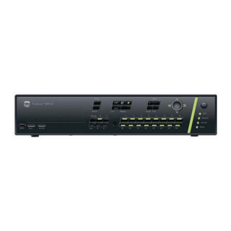
GE TruVision DVR 20 User manual

GE
Security
P/N 1069892-EN • REV 1.1 • ISS 31MAY10
TruVision DVR 20 User Manual

Copyright © 2010 GE Security, Inc.
This document may not be copied in whole or in part or otherwise reproduced without prior
written consent from GE Security, Inc., except where specifically permitted under US and
international copyright law.
Disclaimer The information in this document is subject to change without notice. GE Security, Inc.
(“GE Security”) assumes no responsibility for inaccuracies or omissions and specifically disclaims
any liabilities, losses, or risks, personal or otherwise, incurred as a consequence, directly or
indirectly, of the use or application of any of the contents of this document. For the latest
documentation, contact your local supplier or visit us online at www.gesecurity.com.
This publication may contain examples of screen captures and reports used in daily operations.
Examples may include fictitious names of individuals and companies. Any similarity to names
and addresses of actual businesses or persons is entirely coincidental.
Trademarks and patents GE and the GE monogram are trademarks of General Electric Company. The TruVision is a
trademark of GE Security.
Other trade names used in this document may be trademarks or registered trademarks of the
manufacturers or vendors of the respective products.
Intended use Use this product only for the purpose it was designed for; refer to the data sheet and user
documentation for details. For the latest product information, contact your local supplier or visit
us online at www.gesecurity.com.
Certification and compliance
European Union directives 2004/108/EC (EMC directive): Non-European manufacturers must designate an authorized
representative in the Community. Our authorized manufacturing representative is:
GE Security B.V., Kelvinstraat 7,
6003 DH Weert, The Netherlands.
2002/96/EC (WEEE directive): Products marked with this symbol cannot be disposed of as
unsorted municipal waste in the European Union. For proper recycling, return this product to
your local supplier upon the purchase of equivalent new equipment, or dispose of it at
designated collection points. For more information see: www.recyclethis.info.
2006/66/EC (battery directive): This product contains a battery that cannot be disposed of as
unsorted municipal waste in the European Union. See the product documentation for specific
battery information. The battery is marked with this symbol, which may include lettering to
indicate cadmium (Cd), lead (Pb), or mercury (Hg). For proper recycling, return the battery to your
supplier or to a designated collection point. For more information see: www.recyclethis.info.
Contact information For contact information see our Web site: www.gesecurity.eu.
TruVision DVR 20 User Manual i
Content
Chapter 1 Product introduction 1
Product overview 1
Features 2
Chapter 2 Installation 5
Installation environment 5
Unpacking the TVR 20 and its accessories 5
HDD capacity 6
Connecting devices to the rear panel 7
Alarm inputs and outputs 8
Camera inputs 9
RS-485 port 9
RS-232 port 10
PTZ dome camera set up 10
Wiring the KTD-405 keypad 13
Using the KTD-405 keypad to address PTZ cameras in zone mode 16
Monitor connections 17
Audio inputs and output 17
Chapter 3 eZ setup 19
Chapter 4 Operating instructions 23
Control interfaces 23
Controlling the TVR 20 23
Using the front panel 24
Using the mouse 26
Using the remote control 27
Using a KTD-405/KTD-405-2D keypad 29
Screen overview 31
Chapter 5 Basic operation 35
Turning on the TVR 20 35
Logging on 35
TVR 20 toolbar overview 36
Live mode 37
Controlling a PTZ camera 43
Playing back recorded video 46
Bookmarking recorded video 49
Archiving recently recorded video 50
Searching and playing back recorded video 53
Playing back archived files on a PC 59
Manually acknowledging an alarm 59
Logging off from setup mode 59

ii TruVision DVR 20 User Manual
Turning off the TVR 20 59
Chapter 6 Advanced setup 61
Overview of the Menu toolbar 61
Camera settings 62
Alarm and event settings 72
Schedule settings 79
Network settings 84
Display settings 89
Managing users 91
System setup 94
System information 102
Chapter 7 Web browser 103
Web browser overview 104
Searching recorded video 105
Playing back and archiving recorded video 106
Windows Vista and 7 users 108
Chapter 8 eZ DDNS 111
Chapter 9 Troubleshooting 113
Appendix A Specifications 115
Appendix B Warranty and support 117
Index 119
TVR 20 menu map 122

TruVision DVR 20 User Manual 1
Chapter 1
Product introduction
Product overview
This is the TruVision DVR 20 User Manual for models:
• TVR-2004-500EA
• TVR-2004-1TEA
• TVR-2008-500EA
• TVR-2008-1TEA
• TVR-2016-500EA
• TVR-2016-1TEA
The TruVision DVR 20 (TVR 20) digital video recorder generation is based on H.264
compression technology. It has enhanced recording capacity and improved network
image transmission speed with high image quality. Comprehensive features and
extended event recording settings enable the almost universal application of this DVR
series.
With Graphical User Interface (GUI), users can command specific actions on the
TVR 20 through graphical icons and visual indicators. Simply point, click, and drag the
playback bar on the screen to playback the recordings in any time slot.
There are multiple control inputs, which include mouse control, front panel control,
remote control, and keypad (KTD-405/KTD405-2D) control. Mouse control is
supported with the simple GUI, offering experienced PC users the similarity of
interactive command of a computer-controlled device. All GUI functions can be
operated via front panel, IR remote, and keypad as well.
The TVR 20 is engineered for express operations. Setup, copy, search, and playback
recordings in seconds with a simple “point and click” on the command icons.

48BChapter 1: Product introduction
2 TruVision DVR 20 User Manual
Features
This section describes the available TVR 20 features.
Compression
The TVR 20 supports the following video features:
Pentaplex operation (simultaneous live, recording, playback, archiving and remote
viewing)
User friendly GUI with graphical icons and visual indicators
Real-time live display for all cameras
Simultaneous VGA, composite and S-video output
Storage
The TVR 20 supports the following storage features:
Two hot swappable HDD or four internal HDD
Built-in DVD burner
Supports eSATA
Two USB 2.0 ports (located on the front panel) for video archive and mouse usage
Preview and playback
The TVR 20 supports the following preview and playback features:
Built-in DVR calculator for fast recording estimation
Express setup: Located in menu option for quick and easy installation
Express copy: Record video instantly while playing back (USB)
Express Playback: Simply point, click and drag the playback bar to view previous
recordings
Express Search: Use intuitive playback bar with a simple drag & drop operation
Network
The TVR 20 supports the following network features:
Free eZ-DDNS Service
Remote configuration support from built-in web interface
Gigabit Ethernet interface for remote network viewing and controlling
On-screen PTZ control via mouse or front panel

48BChapter 1: Product introduction
TruVision DVR 20 User Manual 3
Other features
The TVR 20 supports the following additional features:
Auto-detect video mode (PAL or NTSC) on startup
Multiple Control Inputs: mouse/front panel/remote control
Audio recording capabilities*
Multi-language support
Watermark capabilities to identify intentional modifications of recorded data
Rack mountable
Support KTD-405/KTD405-2D keypad control
* Feature not available for all models.

48BChapter 1: Product introduction
4 TruVision DVR 20 User Manual

TruVision DVR 20 User Manual 5
Chapter 2
Installation
Installation environment
When installing your product, consider these factors:
• Ventilation
• Temperature
• Moisture
• Chassis load
Ventilation: Do not block any ventilation openings. Install in accordance with the
manufacturer’s instructions. Ensure that the location planned for the installation of
the unit is well ventilated.
Temperature: Consider the unit’s operating temperature (0 to 40°C, 32 to 104°F) and
noncondensing humidity specifications (10 to 90%) before choosing an installation
location. Extremes of heat or cold beyond the specified operating temperature limits
may reduce the life expectancy of the DVR. Do not install the unit on top of other hot
equipment. Leave 44 mm (1.75 in.) of space between rack-mounted DVR units.
Moisture: Do not use the unit near water. Moisture can damage the internal
components. To reduce the risk of fire or electric shock, do not expose this unit to rain
or moisture.
Chassis: Equipment weighing less than 15.9 kg (35 lb.) may be placed on top of the
unit.
Unpacking the TVR 20 and its accessories
When you receive the product, check the package and contents for damage, and
verify that all items are included. There is an item list included in the package. If any
of the items are damaged or missing, please contact your local supplier.
Items shipped with the product include:

49BChapter 2: Installation
6 TruVision DVR 20 User Manual
• IR (infrared) remote control
• Two AAA batteries for the remote control
• AC power cord
• USB mouse
• External power supply unit x 1 (Europe and UK)
• DVR
• TruVision DVR 20 Quick Start Guide
• TruVision DVR 20 User Manual (on CD)
HDD capacity
Storage capacity for the TVR 20 varies depending on the model. Refer to Table 1
below for more information.
Table 1: TruVision DVR 20 model types
Model number Description
TVR-2004-500EA TruVision DVR Model 20, 4 ch, 500 GB
TVR-2004-1TEA TruVision DVR Model 20, 4 ch, 1 TB
TVR-2008-500EA TruVision DVR Model 20, 8 ch, 500 GB
TVR-2008-1TEA TruVision DVR Model 20, 8 ch, 1 TB
TVR-2016-500EA TruVision DVR Model 20, 16 ch, 500 GB
TVR-2016-1TEA TruVision DVR Model 20, 16 ch, 1 TB

49BChapter 2: Installation
TruVision DVR 20 User Manual 7
Connecting devices to the rear panel
Figure 1 below shows the rear panel connections and describes each connector on a
typical TVR 20 digital video recorder. Details may vary for specific models.
Figure 1: Rear panel connections (16-channel model shown)
Required connections
1. Video inputs: Connect up to 16 cameras to the standard BNC video inputs.
2. Monitor A or VGA monitor (default): Connect the main monitor to one of the output connections
Optional connections
3. Audio outputs: Connect up to two audio outputs (depends on model) such as line level devices (for
example, speakers with built-in pre-amplifiers).
4. Audio inputs: Connect up to four to audio input (depends on model) such as microphones.
5. Monitor B: Connect a spot monitor (Mon B) to the spot monitor output. The VGA monitor must
support 800 x 600 Hz resolution.
6. RS-232 connector: Connect an RS-232 cable from a device such as a PC to the 9-pin D-sub input.
7. RS-485/RS-422 connector: For telemetry control or remote control via RS-485 keypads
8. Alarm input: Connect up to 16 dry contacts (depends on model). NO and NC supported.
9. Alarm output: Connect up to four NO/NC alarm output relays (depends on model).
10. LAN: Connect the network devices.
11. e-SATA: Connect the e-SATA for archive and storage expansion.
12. USB port: Insert USB devices. USB CD/DVD burner and USB HDD are not supported.
Power connection
13. Power socket: Connect the power cord to the TVR 20. Be sure that all devices are connected and
turned on before turning on the unit. Use the external power supply unit provided.

49BChapter 2: Installation
8 TruVision DVR 20 User Manual
Alarm inputs and outputs
Table 2: Number of inputs and outputs
4-channel TVR 20 4 external alarm inputs 1 internal alarm output
8-channel TVR 20 8 external alarm inputs 2 internal alarm outputs
16-channel TVR 20 16 external alarm inputs 4 internal alarm outputs
Alarm inputs
There is a pin connector on the rear panel to connect the alarm inputs. The number
of pins depends on the TVR 20 model. They can be wired normally open (NO) or
normally closed (NC). They are configured in section “Responding to an alarm” on
page 73.
Note: Do not attempt to wire any accessories directly to the I/O connector on the rear
panel. These connections require dry contact (voltage free) closure to activate.
Figure 2: Programmable alarm inputs
Alarm input with NO in idle state Alarm input with NO in idle state
Alarm outputs
The four alarm output relays respond to input alarms and triggers. They can be
configured as NO or NC in section “Alarm and event notification” on page 75.
Table 3: Alarm output pins
Alarm out number Pin Description
Alarm out 1 1 NO (Normally Open)
2 C (Common)
3 NC (Normally Closed)

49BChapter 2: Installation
TruVision DVR 20 User Manual 9
Alarm out number Pin Description
Alarm out 2 1 NO (Normally Open)
2 C (Common)
3 NC (Normally Closed)
Alarm out 3 1 NO (Normally Open)
2 C (Common)
3 NC (Normally Closed)
Alarm out 4 1 NO (Normally Open)
2 C (Common)
3 NC (Normally Closed)
Figure 3: Alarm output relay in idle state
Camera inputs
Connect cameras to the TVR 20 using 75-ohm video coaxial cables with BNC
connectors. There are two BNC jacks for each camera. Either jack can receive a
camera signal. The signal is looped (directly connected to the other jack), making the
camera signal available to other equipment.
The camera input connectors are auto terminating. This means that the input signal
will automatically be terminated with 75-Ohms unless a second cable is connected to
the second BNC connector of the same camera input.
Make sure there is 75-Ohm termination at the end of the video line if the signal is
looped through the TVR 20.
RS-485 port
The RS-485 port is used for pan, tilt, zoom control of PTZ cameras as well as for
keypads. See “RS-232 and RS-485 port settings” on page 96 to configure this port. See
Figure 4 on page 10 for the serial pin outs for the configuration.

49BChapter 2: Installation
10 TruVision DVR 20 User Manual
Figure 4: RS-485 pins
RS-232 port
The RS-232 port is provided for use with GE's ProBridge text insertion interface
modules in conjunction with compatible CBR, PB3, POS (point of sale) and ATM
(automated teller machine) systems. See “RS-232 and RS-485 port settings” on page
96 to configure this port.
Table 4: RS-232 pins
Pin Description
2 TX
3 RX
5 Ground
PTZ dome camera set up
Use the USB mouse provided or the optional KTD-405 keypad for local telemetry
control. If using the TVR 20 over a network, use the web browser to control the PTZ
dome cameras.
The supported protocols are: GE, Pelco-D, and Pelco-P
For information on setting up the PTZ protocols and presets see “PTZ setup” on page
70 and “RS-232 and RS-485 port settings” on page 96.
Connecting a TVR 20 to a PTZ dome camera
Use the input/output box that is supplied with the KTD-405 keypad to connect both a
PTZ dome camera and a keypad to the TVR 20. See Figure 5 on page 11.

49BChapter 2: Installation
TruVision DVR 20 User Manual 11
Figure 5: Connecting a TVR 20 to a PTZ dome camera
Configuring the PTZ protocols for GE Security cameras
Before the PTZ cameras are assembled in their housings, set their protocol and
address DIP switches for the TVR 20. See Table 5 below for different GE Security PTZ
camera settings.
If you are using PTZ cameras from another company, please refer to their
configuration instructions.
Table 5: PTZ protocols for GE Security cameras
Camera Switch setting
TruVision Mini PTZ
12X: Indoor Dome
Protocol DIP switches
000000
RS-485
communication DIP
switches
0000
Camera site ID DIP
switches
0000000000
1. Protocol DIP switches;
2. RS-485 communication DIP switches;
3. Camera site ID DIP switches

49BChapter 2: Installation
12 TruVision DVR 20 User Manual
Camera Switch setting
TruVision Mini PTZ
12X: Outdoor Dome
Protocol DIP switches
000000
RS-485
communication DIP
switches
0000
Camera site ID DIP
switches
0000000000
1. Protocol DIP switches;
2. RS-485 communication DIP switches;
3. Camera site ID DIP switches
TruVision Dome 16X
PTZ
Protocol switches 1011
Camera site ID
address switches
0000
Baud rate 0000
1. Address switches;
2. Baud switches;
3. Protocol switches
CyberDome Protocol switches Auto
Camera site ID
address switches
0000000000
CyberDome II Protocol switches 00000
Camera site ID
address switches
0000000000
1. Protocol switches;
2. Camera site ID address switches

49BChapter 2: Installation
TruVision DVR 20 User Manual 13
Camera Switch setting
Legend Protocol switches 5
Address switches 0000
Wiring the KTD-405 keypad
The KTD-405 keypad uses RS-485 simplex wiring. The signal is transferred by a single
twisted pair line. An unshielded CAT5 network cable is recommended for normal
applications. Use a shielded CAT5 cable if the cables could be exposed to
interference.
The maximum number of TVR 20s that can be installed in one bus is 31, with a
maximum cable length of 1200 m. Both can be expanded using a signal distributor.
Both the first and the last device in series should be terminated with 120 Ohm
resistance to minimize line reflections. See Figure 6 below.
Figure 6: RS-485 bus serial wiring
1. KTD-405 keypad
2. I/O box
3. TVR 20
The cable length from box to device cannot exceed 2 m when using connector boxes.
See Figure 7 on page 14.

49BChapter 2: Installation
14 TruVision DVR 20 User Manual
Figure 7: RS-485 bus serial wiring with connector boxes
1. KTD-405 keypad
2. I/O box
3. TVR 20
4. Connector box
Use an RS-485 signal distributor for a star wiring configuration. See Figure 8 below.
Figure 8: Star wiring with RS-485 signal distributor
Correct
1. KTD-405 keypad
2. I/O box
3. TVR 20
4. RS-485/KTD-83 distributor

49BChapter 2: Installation
TruVision DVR 20 User Manual 15
Incorrect
Use an RS-485/KTD-83 signal distributor to increase the maximum number of devices
on the bus as well as the total range. Each distributor output provides another RS-
485 bus, extending the output an additional 1200 m. Up to 31 TVR 20s can be
connected to each output. See Figure 9 below.
Figure 9: Expanding the system with an RS-485 signal distributor
Caution: Most signal distributors are unidirectional. This means that the signal only
flows from the input towards the outputs. Consequently it is not possible to connect
several keypads.
See “RS-232 and RS-485 port settings” on page 96 to configure the RS-485 port
communication settings.

49BChapter 2: Installation
16 TruVision DVR 20 User Manual
12BUsing the KTD-405 keypad to address PTZ
cameras in zone mode
The KTD-405 keypad can programmed to operate in zone mode which allows you to
use several DVRs and cameras. A zone is a remote switching device, such as a DVR,
that serves a group of cameras. A system can be divided into as many as 32 zones,
and each zone can have up to 32 cameras depending on the type of KTD-405 keypad
used. See Table 6 below for the list of PTZ camera site address values by zone.
To call up a camera in a zone, you must know the zone number and camera number.
See Table 6 below for the list of receiver site address values by zone.
Table 6: PTZ camera site address values by zone
Zone number
Camera
input 1 2 3 4 5 6 7 8 9 10 11 12 13 14 15 16
1 0 32 64
96 128 160
192
224
256
288
320
352
384 416 448
480
2 1 33 65
97 129 161
193
225
257
289
321
353
385 417 449
481
3 2 34 66
98 130 162
194
226
258
290
322
354
386 418 450
482
4 3 35 67
99 131 163
195
227
259
291
323
355
387 419 451
483
5 4 36 68
100 132 164
196
228
260
292
324
356
388 420 452
484
6 5 37 69
101 133 165
197
229
261
293
325
357
389 421 453
485
7 6 38 70
102 134 166
198
230
262
294
326
358
390 422 454
486
8 7 39 71
103 135 167
199
231
263
295
327
359
391 423 455
487
9 8 40 72
104 136 168
200
232
264
296
328
360
392 424 456
488
10 9 41 73
105 137 169
201
233
265
297
329
361
393 425 457
489
11 10 42 74
106 138 170
202
234
266
298
330
362
394 426 458
490
12 11 43 75
107 139 171
203
235
267
299
331
363
395 427 459
491
13 12 44 76
108 140 172
204
236
268
300
332
364
396 428 460
492
14 13 45 77
109 141 173
205
237
269
301
333
365
397 429 461
493
15 14 46 78
110 142 174
206
238
270
302
334
366
398 430 462
494
16 15 47 79
111 143 175
207
238
271
303
335
367
399 431 463
495
17 16 48 80
112 144 176
208
240
272
304
336
368
400 432 464
496
18 17 49 81
113 145 177
209
241
273
305
337
369
401 433 465
497
19 18 50 82
114 146 178
210
242
274
306
338
370
402 434 466
498
20 19 51 83
115 147 179
211
243
275
307
339
371
403 435 467
499
21 20 52 84
116 148 180
212
244
276
308
340
372
404 436 468
500
22 21 53 85
117 149 181
213
245
277
309
341
373
405 437 469
501
23 22 54 86
118 150 182
214
246
278
310
342
374
406 438 470
502
Table of contents
Other GE DVR manuals

GE
GE Digi-4 User manual

GE
GE DVMRe CT II User manual

GE
GE DSR-2000e User manual

GE
GE Calibur DSR-1000eZ User manual

GE
GE MVS-44 User manual

GE
GE Kalatel 0150-0255C User manual

GE
GE MobileView 4 User manual

GE
GE TruVision DVR 10 User manual

GE
GE TruVision DVR 10 Installation guide

GE
GE Calibur DVMR Triplex eZ User manual

GE
GE DVSR xU User manual

GE
GE Appliances 30 User manual

GE
GE TLE Scalable 40 User manual

GE
GE GE Security DVMRe Triplex User manual

GE
GE Kalatel DVMRe-4L User manual

GE
GE Digia II User manual

GE
GE SymDec 4 User manual

GE
GE TruVision DVR 30 User manual

GE
GE TruVision DVR 30 User manual

GE
GE MobileView User manual