Chipkin CAS-2700-24 User manual

©2014 Chipkin Automation Systems, 3381 Cambie St- Box 211, Vancouver, BC, Canada, V5Z 4R3
Tel: (866) 383-1657, Fax: (416) 915-4024
Email: [email protected]om Website: www.chipkin.com
CAS-2700-24
SMA Gateway
Modbus / BACnet / HTML Gateway
CAS-2700-24
SMA
Modbus (RTU and TCP) / BACnet / HTML Gateway

2014© Chipkin Automation Systems, 3495 Cambie St. Unit211, Vancouver, BC, Canada, V5Z 4R3
Tel: (866) 383-1657, Fax: (416) 915-4024
Blank Page

CAS-2700-24 SMA Gateway Manual Page 3 of 62
2014© Chipkin Automation Systems, 3495 Cambie St. Unit211, Vancouver, BC, Canada, V5Z 4R3
Tel: (866) 383-1657, Fax: (416) 915-4024
TABLE OF CONTENTS
TABLE OF CONTENTS..........................................................................................................................3
1. SMA Gateway Description ...........................................................................................................6
2. Connections ................................................................................................................................7
2.1. Block Diagram................................................................................................................................. 7
2.2. Wiring / Connections...................................................................................................................... 8
2.2.1. Modbus RTU Connections ....................................................................................................... 8
2.3. Limitations and Best Practices........................................................................................................ 9
3. Configuration and Settings ........................................................................................................10
3.1. SMA Sunny Webbox Connection Settings....................................................................................10
3.2. SMA Sunny Webbox Configuration Options ................................................................................10
3.3. ModbusTCP Settings..................................................................................................................... 11
3.4. ModbusRTU Settings .................................................................................................................... 11
3.5. BACnet IP Settings ........................................................................................................................ 12
3.6. Change Configuration Settings .....................................................................................................12
3.7. Adding SMA Devices..................................................................................................................... 14
3.8. Configuration Tools ...................................................................................................................... 15
4. Reading Data using HTML / Web Browser ..................................................................................16
5. Reading Modbus Data ...............................................................................................................17
5.1. Modbus Function Supported (RTU and TCP)................................................................................ 17
5.2. SMA Modbus Data Map ...............................................................................................................17

CAS-2700-24 SMA Gateway Manual Page 4 of 62
2014© Chipkin Automation Systems, 3495 Cambie St. Unit211, Vancouver, BC, Canada, V5Z 4R3
Tel: (866) 383-1657, Fax: (416) 915-4024
5.3. Interpreting Modbus Data............................................................................................................ 25
5.4. Test Procedure –Use CAS Modbus Scanner ................................................................................26
6. Reading BACnet Data ................................................................................................................29
6.1. Most Common BACnet Problem ..................................................................................................29
6.2. Interpreting BACnet Data .............................................................................................................29
6.3. BACnet Objects.............................................................................................................................29
6.4. BACnet Test Procedure.................................................................................................................38
7. Commissioning, Diagnostics and Trouble Shooting .....................................................................44
7.1. What to Take to Site for Commissioning...................................................................................... 44
7.2. Gateway Status............................................................................................................................. 48
7.3. Gateway Diagnostics ....................................................................................................................48
7.4. Debug log...................................................................................................................................... 49
7.5. Veeder Device Connection ........................................................................................................... 51
7.6. Another Method for Changing the IP Address - DHCP.................................................................53
7.7. Discovering the Gateway.............................................................................................................. 54
7.8. Downloading New Firmware........................................................................................................54
8. Specifications............................................................................................................................56
9. SMA Enumerations....................................................................................................................57
9.1. SMA Invertor Data Enumerations ................................................................................................57
9.1.1. Mode ..................................................................................................................................... 57
9.1.2. Grid Type ............................................................................................................................... 57
9.1.3. Balancer................................................................................................................................. 57

CAS-2700-24 SMA Gateway Manual Page 5 of 62
2014© Chipkin Automation Systems, 3495 Cambie St. Unit211, Vancouver, BC, Canada, V5Z 4R3
Tel: (866) 383-1657, Fax: (416) 915-4024
9.1.4. Backup State.......................................................................................................................... 57
9.1.5. Error....................................................................................................................................... 58
9.2. SMA Sunny Island Data Enumerations .........................................................................................59
9.2.1. Mode ..................................................................................................................................... 59
9.2.2. Invertor Operating State (InvOpStt) ...................................................................................... 59
9.2.3. Relay State (Rly1Stt, Rly2Stt)................................................................................................. 59
9.2.4. Battery Charging Process (BatChrgOp) .................................................................................59
9.2.5. Absorption Phase (AptPhs).................................................................................................... 59
9.2.6. GnDmdSrc.............................................................................................................................. 59
9.2.7. GnStatus ................................................................................................................................ 60
9.2.8. GnRnStatus............................................................................................................................ 60
9.2.9. CHPStatus.............................................................................................................................. 60
9.2.10. Address (Adr) ..................................................................................................................... 60
9.2.11. Operating Status (OpStt) ................................................................................................... 60
9.2.12. Card Status (CardStt) ......................................................................................................... 61
9.2.13. Error ................................................................................................................................... 61
10. Revision History.....................................................................................................................62

CAS-2700-24 SMA Gateway Manual Page 6 of 62
2014© Chipkin Automation Systems, 3495 Cambie St. Unit211, Vancouver, BC, Canada, V5Z 4R3
Tel: (866) 383-1657, Fax: (416) 915-4024
1. SMA Gateway Description
The SMA Gateway connects to a SMA Sunny Webbox via an Ethernet (TCP/IP) connection. The SMA
Gateway can then be configured to poll for data values from a number of devices that are connected to
the Webbox. These devices can be Sunny Invertors, SensorBox, or Sunny Islands.
After configuration, the Gateway will poll and read the data from the SMA devices and stores it
internally. When a remote system requests data, this data is served in a form that is appropriate to the
requesting protocol (Modbus TCP/RTU or BACnet). In the event that the connection to the SMA
Webbox is lost, or data cannot be read, the gateway can signal this to the remote data clients by
changing all the values currently stored to a predefined default value.
The Gateway requires configuration that will be described later in this document.

CAS-2700-24 SMA Gateway Manual Page 7 of 62
2014© Chipkin Automation Systems, 3495 Cambie St. Unit211, Vancouver, BC, Canada, V5Z 4R3
Tel: (866) 383-1657, Fax: (416) 915-4024
2. Connections
2.1. Block Diagram
CAS-2700-24 SMA Gateway Manual Page 8 of 62
2014© Chipkin Automation Systems, 3495 Cambie St. Unit211, Vancouver, BC, Canada, V5Z 4R3
Tel: (866) 383-1657, Fax: (416) 915-4024
2.2. Wiring / Connections
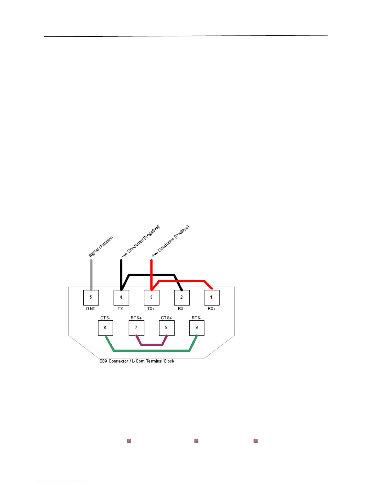
2.2.1. Modbus RTU Connections
Port 0 –RS485 Mode Terminals
All 4 jumpers required for 2 wire operation.
CAS recommends the use of 3 conductors for so called 2-Wire RS485.
The signal common is there for purpose.

CAS-2700-24 SMA Gateway Manual Page 9 of 62
2014© Chipkin Automation Systems, 3495 Cambie St. Unit211, Vancouver, BC, Canada, V5Z 4R3
Tel: (866) 383-1657, Fax: (416) 915-4024
2.3. Limitations and Best Practices
Maximum Number of SMA Sunny Webboxes per Gateway
Only 1 SMA Sunny Webbox can be connected to a single gateway.
RS232 Best Practices
We recommend a maximum of 30ft for the RS232 cable. A well-made cable in a clean environment
can easily run to 100ft and provide satisfactory performance.

CAS-2700-24 SMA Gateway Manual Page 10 of 62
2014© Chipkin Automation Systems, 3495 Cambie St. Unit211, Vancouver, BC, Canada, V5Z 4R3
Tel: (866) 383-1657, Fax: (416) 915-4024
3. Configuration and Settings
3.1. SMA Sunny Webbox Connection Settings
To poll for data from a Sunny Invertor, Sunny Island, or SensorBox all that is needed is the IP address
of the Sunny Webbox that these devices are connected to.
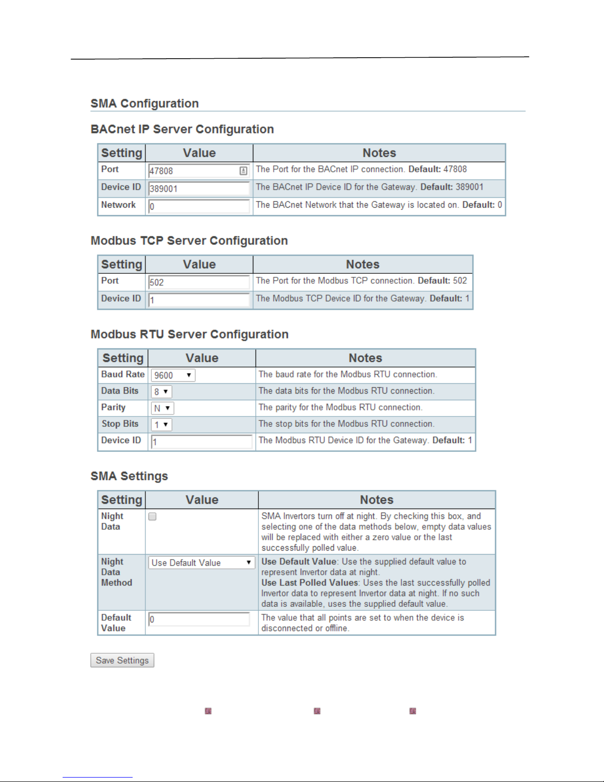
3.2. SMA Sunny Webbox Configuration Options
The following options are set to determine how the data from the SMA devices is handled.
- Night Data –SMA Invertors turn off at night. By enabling this option and selecting one of
the Night data methods, empty values will be replaced with either a zero value or the last
successfully polled value.
- Night Data Method
oUse Default Value –Uses the supplied default value to represent Invertor data at
night.
oUse Last Polled Values –Uses the last successfully polled Invertor data to represent
Invertor data at night. If no such data is available, the supplied default value is used.
- Default Value –The value that all points are set to initially and when the device is
disconnected or offline.

CAS-2700-24 SMA Gateway Manual Page 11 of 62
2014© Chipkin Automation Systems, 3495 Cambie St. Unit211, Vancouver, BC, Canada, V5Z 4R3
Tel: (866) 383-1657, Fax: (416) 915-4024
3.3. ModbusTCP Settings
To connect using ModbusTCP you need to know the IP address of the gateway and the Modbus
‘Station’ number (also known as ‘Device Address’ or ‘Node ID’) and the TCP Port for the
connection.
The following are the configurable parameters for this connection:
-Modbus Station Number (Default value is 1)
-Modbus TCP Port (Default value is 502)
Review section 7.6 Another Method for Changing the IP Address - DHCP to see the default IP
Address settings and how to change them.
3.4. ModbusRTU Settings
To connect using ModbusRTU you need to set the connection parameters correctly and the
Modbus ‘Station’ number (also known as ‘Device Address’ or ‘Node ID’)
- Modbus Station Number (Defaut value is 1)
- Connection Parameters:
oBaud Rate –1200, 2400, 4800, 9600 (Default), 19200, 38400, 76800,
115200
oData Bits –8 (Default), 7
oParity –None (Default), Odd, Even
oStop Bits –1 (Default), 2

CAS-2700-24 SMA Gateway Manual Page 12 of 62
2014© Chipkin Automation Systems, 3495 Cambie St. Unit211, Vancouver, BC, Canada, V5Z 4R3
Tel: (866) 383-1657, Fax: (416) 915-4024
3.5. BACnet IP Settings
BACnet supports discovery. Thus any BACnet tool will discover the gateway and report its
properties. Each gateway must be allocated a unique device instance number and thus this is a
configurable setting.
The configurable BACnet IP connection settings are:
-Device Instance Number (Default value is 389001)
-Port (Default value is 47808)
-Network (Default value is 0)
It is important to note that BACnet messages cannot pass from one subnet to another without a
BACnet technology called BBMD installed. The easiest installation and the best way to avoid this
complication is to set the gateway’s IP address so that it is on the same subnet as the BACnet
data client (usually the BAS / Scada system).
Review section 7.6 Another Method for Changing the IP Address - DHCP to see the default IP
Address settings and how to change them.
3.6. Change Configuration Settings
Use a Web Browser and type the following into the address bar:
http://192.168.1.113/ bin/sma/config/
IP Address of your unit.
CAS-2700-24 SMA Gateway Manual Page 13 of 62
2014© Chipkin Automation Systems, 3495 Cambie St. Unit211, Vancouver, BC, Canada, V5Z 4R3
Tel: (866) 383-1657, Fax: (416) 915-4024
CAS-2700-24 SMA Gateway Manual Page 14 of 62
2014© Chipkin Automation Systems, 3495 Cambie St. Unit211, Vancouver, BC, Canada, V5Z 4R3
Tel: (866) 383-1657, Fax: (416) 915-4024
Change the Settings and click Submit to save them. To cancel changes simply close the
page without submitting.
Note on IP Addresses: Another method is provided to change the Netmask and Gateway
address.
Changes do not take effect until the device restarts. Use the Reset button the web page
or recycle the power.
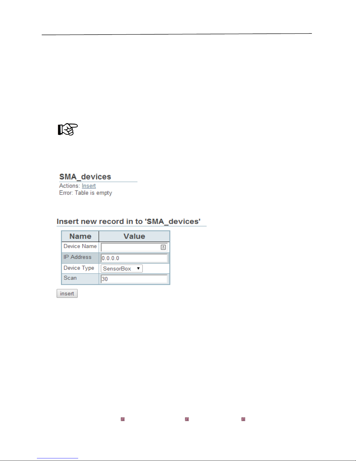
3.7. Adding SMA Devices
Parameters:
Device Name –Name of the device, usually contains serial number, get this value by
running the RPC Client application, see 3.8 Configuration Tools.
IP Address –IP address of the Sunny Webbox that the device is connected to
Device Type –Select one of Invertor, SensorBox, or Sunny Island
Scan –The polling interval, defaulted to 30 seconds.

CAS-2700-24 SMA Gateway Manual Page 15 of 62
2014© Chipkin Automation Systems, 3495 Cambie St. Unit211, Vancouver, BC, Canada, V5Z 4R3
Tel: (866) 383-1657, Fax: (416) 915-4024
3.8. Configuration Tools
In order to complete the configuration process, the names and serial numbers of the SMA devices
are needed.
There is a tool that is required to get this information called the RPC Client.
Please contact Chipkin Automation Systems to get access to this tool and for help with
configuration.
CAS-2700-24 SMA Gateway Manual Page 16 of 62
2014© Chipkin Automation Systems, 3495 Cambie St. Unit211, Vancouver, BC, Canada, V5Z 4R3
Tel: (866) 383-1657, Fax: (416) 915-4024
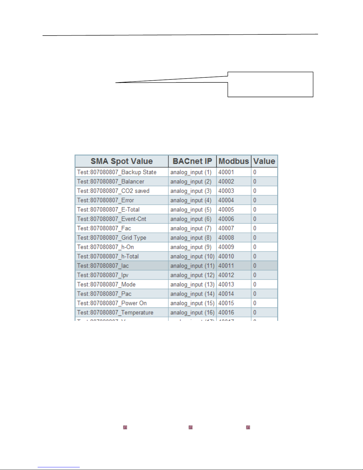
4. Reading Data using HTML / Web Browser
Use a Web Browser to browse to this page.
http://192.168.1.113/bin/sma/report
You are presented with a screen similar to this one.
This screen is useful for seeing the current BACnet and Modbus mappings as well as the current
value of the data point, which is useful for quickly checking that the connections are good and
data is being read.
This is the IP address of your
gateway

CAS-2700-24 SMA Gateway Manual Page 17 of 62
2014© Chipkin Automation Systems, 3495 Cambie St. Unit211, Vancouver, BC, Canada, V5Z 4R3
Tel: (866) 383-1657, Fax: (416) 915-4024
5. Reading Modbus Data
Need to know more about Modbus? Read this guide.
http://www.chipkin.com/september-2010-newsletter
5.1. Modbus Function Supported (RTU and TCP)
The Gateway supports functions 1, 2, 3, and 4. Most masters should be configured to use
function 3 (Read Holding Registers). However it will respond to polls that use the other functions
with offset equal to zero. You can read this data as 3xxxx, 1xxxx, 0xxxx or 4xxxx data.
5.2. SMA Modbus Data Map
For the following registers, each set of data (Invertor, SensorBox, and Sunny Island) will be
described as if it was the first device configured. Each additional device added will be offset by
100. So the first device will have data starting at 40001, the second device will have data
starting at 40101, the third device will have data starting at 40201, etc.
Typical Invertor Data
Modbus Address
Value Stored
40001
BackUp State
40002
Balancer
40003
CO2 Saved
40004
Error
40005
E-Total
40006
Event-Cnt
40007
Fac

CAS-2700-24 SMA Gateway Manual Page 18 of 62
2014© Chipkin Automation Systems, 3495 Cambie St. Unit211, Vancouver, BC, Canada, V5Z 4R3
Tel: (866) 383-1657, Fax: (416) 915-4024
40008
Grid Type
40009
h-On
40010
h-Total
40011
Iac
40012
Ipv
40013
Mode
40014
Pac
40015
Power On
40016
Temperature
40017
Vac
40018
Vpv
40019
Serial Number
40020
VacL1
40021
VacL2
40022
Vpv-PE
40023
Max Temperature
40024
Max Vpv
40025
Vfan
Note 1: Balancer, Error, Mode, Grid Type are enumerated values. See section 9: SMA
Enumerations for more information
Note 2: All of these values will be sent a 16 bit values, therefore any real (decimal) values will be
sent as their whole number part (i.e. 24.3 will be sent as 24). If you require the entire decimal
value, please contact Chipkin Automation Systems.

CAS-2700-24 SMA Gateway Manual Page 19 of 62
2014© Chipkin Automation Systems, 3495 Cambie St. Unit211, Vancouver, BC, Canada, V5Z 4R3
Tel: (866) 383-1657, Fax: (416) 915-4024
Typical SensorBox Data
Modbus Address
Value Stored
40001
ExlSollrr
40002
IntSollrr
40003
OpTm
40004
TmpAmb F
40005
TmpMdul F
40006
TmpAmb C
40007
TmpMdul C
40008
WindVel m/s
40009
WindVel mph
Note 1: All of these values will be sent a 16 bit values, therefore any real (decimal) values will be
sent as their whole number part (i.e. 24.3 will be sent as 24). If you require the entire decimal
value, please contact Chipkin Automation Systems.
Typical Sunny Island Data
Modbus Address
Value Stored
40001
Adr
40002
AptPhs
40003
AptTmRmg
40004
BatChrgOp
40005
BatChrgVtg

CAS-2700-24 SMA Gateway Manual Page 20 of 62
2014© Chipkin Automation Systems, 3495 Cambie St. Unit211, Vancouver, BC, Canada, V5Z 4R3
Tel: (866) 383-1657, Fax: (416) 915-4024
40006
BatSoc
40007
BatSocErr
40008
BatTmp
40009
BatVtg
40010
CardStt
40011
ChpPwrAt
40012
ChpRmgTm
40013
ChpStrRmgTm
40014
ChpStt
40015
EgyCntIn
40016
EgyCntOut
40017
EgyCntTm
40018
Error
40019
E-Total
40020
E-Total-In
40021
ExtCur
40022
ExtCurSlv1
40023
ExtCurSlv2
40024
ExtCurSlv3
40025
ExtFrq
40026
ExtPwrAt
40027
ExtPwrAtSlv1
Table of contents
Other Chipkin Gateway manuals


Popular Gateway manuals by other brands


ZyXEL Communications
ZyXEL Communications P-793H 601156 quick start guide

D-Link
D-Link DVG-5008S user manual

HMS Networks
HMS Networks Intesis INBACDAL1280200 Installation sheet

AudioCodes
AudioCodes MediaPack MP-40x series user manual

Mercury
Mercury SMARTCRAFT manual

Extron electronics
Extron electronics ShareLink 250 W Setup guide


