GE PACSystems RXi-XP IPC Quick user guide

Internal
GFK-2990
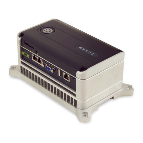
PACSystems* RXi Box IPC-XP
Hardware Reference Manual
Edition 3.0
(HWRMRXiXP)

PACSystems RXi Box IPC-XP Hardware Reference Manual GFK-2990 2
Internal
Document History
Edition Description Date by
Draft 1.0
New document based on 042 Release 1.0
Typos corrected, product renamed, links to BIOS guide removed,
doubled tables removed, power consumption for new system
configurations updated, CFAST Slot Type I specified
2013-11-25 PS
1.0 First release, footer link to .docx file removed 2014-02-04 PS
3.0
Including RXMxx0, RXM1x2 sheet metal cabinet and PERC01/02 riser
cards configurations, weight table corrected, NVRAM section corrected,
preferred mounting orientation added, minor typos removed, more
configurations for power consumption added
2015-06-05
2015-08-31
2015-10-05
PS

PACSystems RXi Box IPC-XP Hardware Reference Manual GFK-2990 3
Internal
Preface
Legal Information
Legal Disclaimers
The information in this manual is proprietary to and is the confidential information of GE Intelligent Platforms,
Inc. and may not be reproduced in whole or in part, for any purpose, in any form or by any means, electronic,
mechanical, recording, or otherwise, without written consent of GE Intelligent Platforms, Inc. Use, disclosure,
and reproduction is permitted only under the terms of a GE Intelligent Platforms license agreement or explicit
written permission of GE Intelligent Platforms. You are not authorized to use this document or its contents until
you have read and agreed to the applicable license agreement. Receipt of this publication is considered
acceptance of these conditions. All information contained in this document has been carefully checked and is
believed to be entirely reliable and consistent with the product that it describes. However, no responsibility is
assumed for inaccuracies. GE Intelligent Platforms assumes no liability due to the application or use of any
product or circuit described herein; no liability is accepted concerning the use of GE Intelligent Platforms
products in life support systems. GE Intelligent Platforms reserves the right to make changes to any product
and product documentation in an effort to improve performance, reliability, or design.
THIS DOCUMENT AND ITS CONTENTS ARE PROVIDED AS IS, WITH NO WARRANTIES OF ANY KIND, WHETHER
EXPRESS OR IMPLIED, INCLUDING WARRANTIES OF DESIGN, MERCHANTABILITY, AND FITNESS FOR A
PARTICULAR PURPOSE, OR ARISING FROM ANY COURSE OF DEALING, USAGE, OR TRADE PRACTICE.
Changes or modifications to this unit, not expressly approved by GE Intelligent Platforms, could void the user’s
authority to operate the equipment.
All computer code and software contained in this document is licensed to be used only in connection with a GE
Intelligent Platforms hardware product. Even if this code or software is merged with any other code or
software program, it remains subject to the terms and conditions of this license. If you copy, or merge, this
code or software, you must reproduce and include all GE Intelligent Platforms copyright notices and any other
proprietary rights notices.
The content of this manual if furnished for informational use only and is subject to change without notice.
Reverse engineering of any GE Intelligent Platforms product is strictly prohibited.
In no event will GE Intelligent Platforms be liable for any lost revenue or profits or other special, indirect,
incidental and consequential damage, even if GE Intelligent Platforms has been advised of the possibility of
such damages, as a result of the usage of this document describes. The entire liability of GE Intelligent
Platforms shall be limited to the amount paid by you for this document and its contents.
GE Intelligent Platforms shall have no liability with respect to the infringement of copyrights, trade secrets, or
any patents by this document of any part thereof. Please see the applicable software license agreement for full
disclaimer or warranties and limitations of liability.
This disclaimer of warranty extends to GE Intelligent Platforms’ licensees, to licensees transfers, and to
licensees customers or users and is in lieu of all warranties expressed, implied, or statutory, included implied
warranties of scalability or fitness for a particular purpose.
The GE logo is a trademark of GE, Inc. Other brand names and product names contained herein may be
claimed as the property of others.

PACSystems RXi Box IPC-XP Hardware Reference Manual GFK-2990 4
Internal
GE Intelligent Platforms, Inc., 2500 Austin Drive, Charlottesville, VA 22911, U.S.A.
Regulatory compliance
Products sold or transferred between companies or operated on company premises (factory floor, laboratory)
do not need CE, FCC or equivalent certification. Boards or subsystems which cannot provide a useful function
on their own do not need certification.
Certification can only be granted to complete and operational systems. There are authorized testing agencies,
regulatory organizations and laboratories who will issue certificates of compliance after system testing.
GE Intelligent Platforms designs and tests all their products for EMI/EMC conformance. Where GE Intelligent
Platforms supplies a complete/functional system for use by end users a certificate will be cited in the
manuals/documents which are provided with the products.
Products manufactured by GE Intelligent Platforms should normally be suitable for use in properly designed
and produced customer equipment (system boxes or operational systems) without any major redesign or
additional filtering. However, the systems might not conform to specific regulations once assembled and used.
The system integrator or installer must test for compliance as required in his country or by the intended
application and certify this to the end user.
Open-Source Notices
This product contains VHDL source code, which is copyrighted open source software that is licensed under the
GNU Lesser General Public License (LGPL) (See chapter 9, Appendix). In accordance with LGPLv2.1 licensing,
you may obtain the corresponding source code from GE Intelligent Platforms for a period of three years after
our last shipment of this product, which will be no earlier than 2017. Please include the model and serial
ESD/EMI issues
ESD (Electro-Static Discharge) and EMI (Electro-Magnetic Interference) issues may show up in complete and
operational systems. There are many ways to avoid problems with these issues.
Any operational system with cables for I/O signals, connectivity or peripheral devices provides an entry point
for ESD and EMI. If GE Intelligent Platforms does not manufacture the complete system, including enclosure
and cables, it is the responsibility of the system integrator and end user to protect their system against
potential problems. Filtering, optical isolation, ESD gaskets and other measures might be required at the
physical point of entry (enclosure wall of box or rack). For example it is state-of-the-art that protection cannot
be done at the internal connector of an RTM if a cable is attached and routed outside the enclosure. It has to
be done at the physical entry point as specified above.
Products manufactured by GE Intelligent Platforms should normally be suitable for use in properly designed
and produced customer equipment (system boxes or operational systems) without any major redesign.
However, the systems might be subject to problems and issues once assembled, cabled and used. The end
user, system integrator or installer must test for possible problems and in some cases show compliance to
local regulations as required in his country or by the intended application.

PACSystems RXi Box IPC-XP Hardware Reference Manual GFK-2990 5
Internal
Waste Disposal
The mark or symbol on any electrical or electronic product shows that this product may not be disposed of in a
trash bin. Such goods have to be returned to the original vendor or to a properly authorized collection point.
The black bar underneath the waste bin symbol shows that the product was placed on the market after 13
August 2005. Alternatively the date of ‘placed on the market’ is shown in place of the bar symbol.
Advice on Batteries
There is danger of explosion if the battery is incorrectly replaced. Replace only with the same or equivalent
type recommended by GE Intelligent Platforms. Dispose used batteries according to instructions of GE
Intelligent Platforms and applicable local regulations.
CE conformance declaration
CE certification is required in EU countries for equipment which is used or operated by the end user. Products
sold or transferred between companies or operated on company premises (factory floor, laboratory) do not
need CE certification.
CE certification can only be granted to complete and operational systems. Boards or subsystems which cannot
provide a useful function on their own do not need CE certification.
GE Intelligent Platforms designs and tests all their products for EMI/EMC conformance. Products manufactured
by GE Intelligent Platforms should normally be suitable for use in properly designed and produced customer
equipment (system boxes or operational systems) without any major redesign or additional filtering. The
system integrator or installer must, in any case, test for CE compliance and certify this to the end user.
Where GE Intelligent Platforms supplies a complete/functional system for use by end users in EU countries a CE
certificate will be cited in the manuals/documents which are provided with the products. The CE (and year of
certification) symbol is shown on the equipment, typically on the type or S/N label or close to the power cable
entry.
GE Intelligent Platforms have tested their boards using their own card cages (chassis). Test results of these
tests are available upon request.

PACSystems RXi Box IPC-XP Hardware Reference Manual GFK-2990 6
Internal
Corporate addresses
Corporate headquarters
GE Intelligent Platforms, Inc.
2500 Austin Drive
Charlottesville, VA 22911
U.S.A.
Phone: +1-800-322-3616
Web: http://www.ge-ip.com/
Germany
US
GE Intelligent Platforms GmbH & Co. KG
Memminger Str. 14
86159 Augsburg
Germany
GE Intelligent Platforms, Inc.
2500 Austin Drive
Charlottesville, VA 22911
U.S.A.
Phone: +49-821-5034-0
Fax: +49-821-5034-119
Phone: +1-800-322-3616
E-Mail: sales.augsburg.ip@ge.com
Web: http://www.ge-ip.com/
GE Intelligent Platforms on the Web:
http://www.ge-ip.com/
For contact and other information (service, warranty, support etc.) see address list in chapter: ‘Support, Service’.

PACSystems RXi Box IPC-XP Hardware Reference Manual GFK-2990 7
Internal
Welcome
This document defines the RXi Box Industrial PC-XP composed of a bCOM6 COM Express module and the
CEC02 or CEC04 Carrier board.
A Computer-On-Module, or COM, is a module with all components necessary for a bootable host computer,
packaged as a super component. A COM requires a Carrier Board to connect I/O and to power up. COMs are
used to build modular solutions and offer OEMs fast time-to-market with reduced development cost. Like
integrated circuits, they provide OEMs with significant freedom in meeting form-fit-function requirements. For
all these reasons the COM methodology has gained much popularity with OEMs in the embedded industry.
The CEC02/CEC04 Carrier boards are based on the PICMG COM Express Module Base Specification.
The RXi Box IPC-XP is based on industrial grade housing for the Module and Carrier components.
Chapter 1 is the introduction
Chapter 2 describes unpacking and inspection
Chapter 3 is about the installation
Chapter 4 lists the resources
Chapter 5 defines the specifications
Chapter 6 describes the hardware
Chapter 7 informs about support, service and warranty
The following documents also cover items relevant to the RXi Box IPC-XP:
•User’s Manual for AMIBIOS8 Setup
•AMIBIOS8 Check Point and Beep Code List
•AMIBIOS8 Error Messages

PACSystems RXi Box IPC-XP Hardware Reference Manual GFK-2990 8
Internal
Typographic Conventions
This manual uses the following notation conventions:
•Italics (sometimes additionally in blue color) emphasize words in text or documentation or chapter titles
or web addresses if underlined.
•Hexadecimal values (base 16) are represented as digits followed by ʹhʹ, for example: 0Ch.
•Hexadecimal values (base 16) are represented as digits preceded by ʹHʹ, for example: H0C.
•Hexadecimal values (base 16) are represented as digits preceded by ʹ$ʹ, for example: $0C.
•Binary values (base 2) are represented as digits followed by ʹbʹ, for example 01b
•The use of a ʹ#ʹ(hash) suffix to a signal name indicates an active low signal. The signal is either true
when it is at logic zero level (voltage close to 0 V) or the signal initiates actions on a high-to-low
transition.
•The use of a ʹ\ʹ(backslash) prefix to a signal name indicates an active low signal. The signal is either true
when it is at logic zero level (voltage close to 0 V) or the signal initiates actions on a high-to-low
transition.
•Text in Courier font indicates a command entry or output from a GE Intelligent Platforms embedded PC
product using the built-in character set.
•Notes, warning symbols and cautions call attention to essential information.
Product Properties
Certification
This product is certified according to:
―CE EN-IEC 60950-1
―EN/IEC 61131-2
For more information about certifications please refer to chapter 6: Specification.
Altitude
Altitude, air pressure and ambient temperature influence the thermal operation of the components described
in this manual. They have been developed and tested at about 500 m (1650 ft.) above sea level at a typical
ambient temperature of 20 °C (68 °F). Because of only marginal variations within a limited range of altitudes
these products operate as specified within altitudes from sea level to 2000 m (~6560 ft.). This is with reference
to temperature ranges of air-cooled versions. GE Intelligent Platforms can assist the user of these components
in planning operation outside this altitude range upon request.
Options
This manual describes the basic product plus all options. Your product may not have all options implemented.
Please verify with your purchase contract which options are implemented. Descriptions of options which are
not implemented obviously do not apply to your product.
Support, Service and Warranty
The manufacturer grants the original purchaser of GE Intelligent Platforms products a warranty of 24 months
from the date of delivery. For details regarding this warranty refer to Terms & Conditions of the initial sale.

PACSystems RXi Box IPC-XP Hardware Reference Manual GFK-2990 10
Internal
Table of Contents
1Introduction ...............................................................................................................................................................................................................15
1.1 PC Design .........................................................................................................................................................................................................15
1.2 Carrier Design................................................................................................................................................................................................15
1.3 COM Express Card Design ......................................................................................................................................................................17
2Unpacking and Inspection ................................................................................................................................................................................19
2.1 Package Contents .......................................................................................................................................................................................19
2.2 Available Accessories ................................................................................................................................................................................20
2.3 Hot Surface .....................................................................................................................................................................................................20
2.4 ESD.......................................................................................................................................................................................................................21
2.5 Initial Inspection ...........................................................................................................................................................................................21
2.6 Unpacking........................................................................................................................................................................................................22
3Installation..................................................................................................................................................................................................................23
3.1 Mounting instruction..................................................................................................................................................................................23
3.1.1 Flat wall mounting .................................................................................................................................................................................23
3.1.2 Slim Mounting...........................................................................................................................................................................................27
3.2 Installation preparation............................................................................................................................................................................29
3.3 General advice ..............................................................................................................................................................................................29
3.4 Required items ..............................................................................................................................................................................................30
3.4.1 Power Supply............................................................................................................................................................................................30
3.4.2 Keyboard.....................................................................................................................................................................................................30
3.4.3 Video Monitor ...........................................................................................................................................................................................30
3.5 Minimum System Requirements.........................................................................................................................................................31
3.5.1 THE POST TEST .........................................................................................................................................................................................31
3.6 Installation of a PCI board.......................................................................................................................................................................32
3.7 Installation of a Mini PCIe add-on card ...........................................................................................................................................34
3.8 Installation of an Internal Hard Disk Drive.....................................................................................................................................35
3.9 Initial Power-On Operation.....................................................................................................................................................................35
3.10 Entering the UEFI Firmware SETUP....................................................................................................................................................36
3.11 Exchange the Battery................................................................................................................................................................................36
4Hardware....................................................................................................................................................................................................................39
4.1 Overview for RXE and RXMxx0 based on the carrier CEC04 ...............................................................................................39
4.2 Overview for RXM1x2 based on the carrier CEC02...................................................................................................................40
4.3 Interfaces .........................................................................................................................................................................................................41
4.3.1 LEDs ...............................................................................................................................................................................................................42
4.3.2 Power Button............................................................................................................................................................................................43
4.3.3 Reset Button..............................................................................................................................................................................................43
4.3.4 Ethernet Interface (Eth1, Eth2, Eth3, Eth4, Eth5; on RXM1x2 Eth1, Eth2, Eth3).....................................................44
4.3.5 Display Port Interface...........................................................................................................................................................................45
4.3.6 VGA Interface (RXM1x2 only)............................................................................................................................................................46
4.3.7 USB 2.0 Connectors (USB1, 2; on RXM1x2 USB1-4) .............................................................................................................47
4.3.8 USB 3.0 Connectors (USB 3,4; not on RXM1x2) ......................................................................................................................48
4.3.9 Power Connector....................................................................................................................................................................................49
4.3.10 Internal SATA Slot..............................................................................................................................................................................50
4.3.11 CFast Slot...............................................................................................................................................................................................50
4.3.12 Serial (COM1,2 or COM1-4; not on RXM1x2) Ports ..........................................................................................................51
4.3.13 Mini PCIe Slot .......................................................................................................................................................................................51
4.3.14 PCIe Slots ...............................................................................................................................................................................................52
4.3.15 PCI Slots..................................................................................................................................................................................................52
4.4 Additional devices .......................................................................................................................................................................................52
4.4.1 Temperature Sensor.............................................................................................................................................................................52
4.4.2 NVSRAM (Non-Volatile Random-Access Memory; not on RXM1x2) ...........................................................................52
5Resources ...................................................................................................................................................................................................................53
5.1 Programmable devices ............................................................................................................................................................................53
5.1.1 SMBUS DEVICES ......................................................................................................................................................................................53

PACSystems RXi Box IPC-XP Hardware Reference Manual GFK-2990 11
Internal
5.2 ETHERNET........................................................................................................................................................................................................53
5.3 PCIE ports ........................................................................................................................................................................................................54
5.4 PCI ROUTING..................................................................................................................................................................................................54
6Specifications...........................................................................................................................................................................................................57
6.1 RXi Box IPC-XP Specifications...............................................................................................................................................................57
7Support, Service and Warranty......................................................................................................................................................................61
7.1 Technical Support.......................................................................................................................................................................................62
7.2 Support on the Web ..................................................................................................................................................................................63
7.3 Warranty..........................................................................................................................................................................................................63
7.4 Error Report....................................................................................................................................................................................................64
8Glossary.......................................................................................................................................................................................................................65
9Appendix.....................................................................................................................................................................................................................67

PACSystems RXi Box IPC-XP Hardware Reference Manual GFK-2990 12
Internal
List of Figures
Figure 1: Packaging..........................................................................................................................................................................................................22
Figure 2; Heat dissipation drawing..........................................................................................................................................................................23
Figure 3: Flat mounting with mounting plates..................................................................................................................................................24
Figure 4: Flat wall mounting through the box – illustration.......................................................................................................................25
Figure 5: Flat wall mounting through the wall – illustration......................................................................................................................26
Figure 6: Clearances slim wall mounting – illustration.................................................................................................................................27
Figure 7: Slim mounting with mounting plate...................................................................................................................................................28
Figure 8: Installation of a PCIe card ........................................................................................................................................................................33
Figure 9: Installation of Mini-PCIe module...........................................................................................................................................................34
Figure 10: Internal SATA installation, vendor is subject to change........................................................................................................35
Figure 11: Removed front panel, view at battery ............................................................................................................................................36
Figure 12: Removed battery........................................................................................................................................................................................37
Figure 13: Retaining clip with battery ....................................................................................................................................................................37
Figure 14: Hardware Overview..................................................................................................................................................................................39
Figure 15: Hardware Overview..................................................................................................................................................................................40
Figure 16: front panel RXE and RXMxx0 ...............................................................................................................................................................41
Figure 17: front panel RXM1x2...................................................................................................................................................................................41
Figure 18: front panel LEDs..........................................................................................................................................................................................42
Figure 19: Power button ................................................................................................................................................................................................43
Figure 20: Reset button..................................................................................................................................................................................................43
Figure 21: Ethernet Interface ......................................................................................................................................................................................44
Figure 22: Display Port....................................................................................................................................................................................................45
Figure 23: VGA interface................................................................................................................................................................................................46
Figure 24: USB 2.0 connectors...................................................................................................................................................................................47
Figure 25: USB 3.0 connectors...................................................................................................................................................................................48
Figure 26: Power connector ........................................................................................................................................................................................49
Figure 27: CFast connector..........................................................................................................................................................................................50
Figure 28: Serial Ports – 2-Slot variant...................................................................................................................................................................51
Figure 29: Serial Ports – 4-Slot variant...................................................................................................................................................................51

PACSystems RXi Box IPC-XP Hardware Reference Manual GFK-2990 13
Internal
List of Tables
Table 1: Order code and system combinations...............................................................................................................................................15
Table 2: Delivery volume...............................................................................................................................................................................................19
Table 3: Available accessories...................................................................................................................................................................................20
Table 4: Front Power LED .............................................................................................................................................................................................42
Table 5: Hard disk activity LED ..................................................................................................................................................................................42
Table 6: User status LED ...............................................................................................................................................................................................42
Table 7: Over temperature LED.................................................................................................................................................................................42
Table 8: Front Power LED .............................................................................................................................................................................................44
Table 9: Ethernet LEDs ...................................................................................................................................................................................................44
Table 10: Display Port signals ....................................................................................................................................................................................45
Table 11: VGA ......................................................................................................................................................................................................................46
Table 12: USB port 1-2 ...................................................................................................................................................................................................47
Table 13: USB port 2-3 ...................................................................................................................................................................................................48
Table 14: Power Connector.........................................................................................................................................................................................49
Table 15: Serial Ports.......................................................................................................................................................................................................51
Table 16: SMBus Devices..............................................................................................................................................................................................53
Table 17: I2C Bus device ...............................................................................................................................................................................................53
Table 18: PCI Express Port usage.............................................................................................................................................................................54
Table 19: PCI Routing......................................................................................................................................................................................................55
Table 20: Environment conditions...........................................................................................................................................................................57
Table 21: Shock & vibration parameters .............................................................................................................................................................57
Table 22: Maximum height usage...........................................................................................................................................................................57
Table 23: Input Power.....................................................................................................................................................................................................58
Table 24: Power Consumption RXi Box IPC-XP.................................................................................................................................................58
Table 25: Regional areas ..............................................................................................................................................................................................61
Table 26: Support contact............................................................................................................................................................................................62

PACSystems RXi Box IPC-XP Hardware Reference Manual GFK-2990 14
Internal

PACSystems RXi Box IPC-XP Hardware Reference Manual GFK-2990 15
Internal
1Introduction
Chapter Scope This chapter describes features, capabilities and compatibilities of the RXi Box IPC-XP,
including the CEC02/CEC04 Carrier board and the bCOM6 module.
1.1 PC Design
The RXi Box IPC-XP consists of a combination of the CEC02/CEC04 carrier board and the bCOM6 COM Express
card, as well a PCI and/or PCI Express riser card and housing w/ heat sink.
There are several system combinations available, for latest info about them please ask our sales team. For a
short summary please check the table below.
Order code
First 6 digits
Cabinet rugged aluminum
Cabinet sheet metal
Carrier
Riser card
Number of PCIe / PCI slots
Number of LAN ports
Number of USB 3.0 / USB 2.0
Number of DisplayPort / VGA
Number of Serial RS232/RS4xx
Cabinet height (mm)
RXE0x0
X
CEC04
-
0/0
5
2/2
1/0
2/0 a
76
RXE2x0
X
CEC04
043
0/2
5
2/2
1/0
2/0 a
121
RXE4x0
X
CEC04
044
0/4
5
2/2
1/0
2/2
158
RXE5x0
X
CEC04
PERC02
2/0
5
2/2
1/0
2/0 a
121
RXE6x0
X
CEC04
PERC01
2/2
5
2/2
1/0
2/2
158
RXM0x0
X
CEC04
-
0/0
5
2/2
1/0
2/0 a
117
RXM1x2
X
CEC02
-
1/0
3
0/4
1/1
0
117
RXM2x0
X
CEC04
043
0/2
5
2/2
1/0
2/0
a
117
RXM4x0
X
CEC04
044
0/4
5
2/2
1/0
2/2
154
RXM5x0
X
CEC04
PERC02
2/0
5
2/2
1/0
2/0
a
117
RXM6x0
X
CEC04
PERC01
2/2
5
2/2
1/0
2/2
154
aOn request available with 1x RS232 and 1x RS4xx
Table 1: Order code and system combinations
All RXi Box IPC-XP contain a reset and a power switch, a CFAST slot type1, an internal SSD 2.5 inch drive bay
and an internal Mini PCIe Slot.
1.2 Carrier Design
This chapter describes the COM Express carrier CEC04 based on PICMG COM Express Module Base
Specification Type 6.

PACSystems RXi Box IPC-XP Hardware Reference Manual GFK-2990 16
Internal
The COM Express Carrier CEC04, used in a RXE and the RXMxx0, provides the following core hardware and
firmware resources:
•Support for COM Express Module Type 6
•Functions available on internal connectors
oMini PCIe slot half/full size
oAlmost standard PCIe slot x4 for use with riser card 043/044
o2 or 4 PCI slots half length, full height on riser card 043/044
oSATA direct drive connect
oBR2032 Lithium Coin Battery
•Functions available on front connector plate
o24V Power Input with PE ground
oReset Button
oPower Button
oDisplay Port
o4x USB-A connector (2x are USB 3.0 capable with bCOM6L14 only) and 1x internal USB 2.0
o5x Ethernet connector
o1x CFast Type 1 bay
o4x Status LED
The COM Express Carrier CEC02, used in the RXM1x2, provides the following core hardware and firmware
resources:
•Support for COM Express Module Type 6
•Functions available on internal connectors
oMini PCIe slot half/full size
oStandard PCIe slot x4 for use with slot in cards
ono PCI slots
oSATA direct drive connect
oBR2032 Lithium Coin Battery
•Functions available on front connector plate
o24V Power Input with PE ground
oReset Button
oPower Button
oDisplay Port
o4x USB-A connector (USB 2.0 capable) and 1x internal USB 2.0
o2x Ethernet connector
o1x CFast Type 1 bay
o4x Status LED

PACSystems RXi Box IPC-XP Hardware Reference Manual GFK-2990 17
Internal
1.3 COM Express Card Design
The bCOM6 CPU modules are fully IBM-AT compatible stand-alone PCs. They are equipped with many functions
in a very small form-factor.
The following COM Express CPU modules are available:
bCOM6L14:
oProcessor
―Intel® Core™ i7-3555LE Processor 2.5GHz
―Intel® Celeron Processor 1047UE, 1.4GHz
―Intel® Core™ i7-3612QE Processor 2.1GHz
oChipset
―Intel® Chipset PCH QM77
oSystem Memory
―One Channel one or two ranks soldered with ECC
―2 GB or 4GB DDR3 SDRAM with 1066 or 1600 MHz
oUEFI
―SPI interface UEFI (16 Mbit)
oLAN
―One INTEL® internal PCI Express Gigabit controller with 82579 external Phy
―Supports 10Mbps, 100Mbps and 1Gbps data transmission
―IEEE 802.3 (10/100Mbps) and IEEE 802.3ab (1Gbps) compliant

PACSystems RXi Box IPC-XP Hardware Reference Manual GFK-2990 18
Internal

PACSystems RXi Box IPC-XP Hardware Reference Manual GFK-2990 19
Internal
2Unpacking and Inspection
Chapter Scope This chapter covers the suggested inspection and preparation considerations and
background information necessary prior to using the RXi Box IPC-XP. Unpacking, initial
inspection, and first-time operation of the RXi Box IPC-XP are covered. Following the
procedures given in the chapter are recommended, and they will verify proper operation
before the product is integrated into your system.
2.1 Package Contents
Qty.
Item
Purpose
1
RXi Box IPC-XP
RXi Box Industrial PC XP
Table 2: Delivery volume

PACSystems RXi Box IPC-XP Hardware Reference Manual GFK-2990 20
Internal
2.2 Available Accessories
The following table lists accessories which are available for the RXi Box IPC-XP:
Item
Purpose
ICRXIACCMP01
10 pcs Slim 80 Mount Kits RXi Box IPC-XP
ICRXIACCMP02
10 pcs Flat Mounting Kits RXi Box IPC-XP
ICRXIACCMP03
10 pcs Slim 70 Mount Kits RXi Box IPC-XP
Table 3: Available accessories
NOTE
Please contact the GE Intelligent Platforms sales department or your sales
representative
for latest information on options and accessories.
NOTE
Accessories are subject to change without notice.
2.3 Hot Surface
WARNING
Hot Surface!
If
the RXi Box IPC-XP operates by an enhanced ambient temperature more than 50° C
the surface of the
housing, specially the heat sink, can reach a temperature of 70° C
and above
. Therefore be careful and do not touch the RXi Box IPC-XP with bare
fingers. Install the
RXi Box IPC-XP only in rooms with restricted access.
Table of contents
Other GE Industrial PC manuals