8838 User Guide (BB1857-H)
Cleaning and Disinfection
7
Caring for the Transducer
The transducer may be damaged during use or processing, so it must be checked
before use for cracks or irregularities in the surface. It should also be checked
thoroughly once a month following the procedure in
Care and Cleaning
.
Cleaning and Disinfection
To ensure the best results when using BK Medical equipment, it is important to
maintain a strict cleaning routine.
Full details of cleaning and disinfection procedures can be found in
Care and
Cleaning
that accompanies this user guide. A list of disinfectants and disinfection
methods that the transducer can withstand are listed in the Product Data sheet.
Sterile covers are available. See the Product Data sheet for more information.
Starting Imaging
All equipment must be cleaned and disinfected before use.
Connecting the Transducer
WARNING
Reproc-w2
Users of this equipment have an obligation and responsibility to provide the highest
possible degree of infection control to patients, co-workers and themselves. The
instructions in this book are meant as a guide. To avoid cross contamination, follow all
infection control policies (including for reprocessing, packing and storage) for personnel
and equipment that have been established for your office, department, or hospital.
WARNING
T-w5
To prevent electrical shock and damage to the transducer, the connector pins in the
transducer plug must always be completely dry before you connect to a system.
WARNING
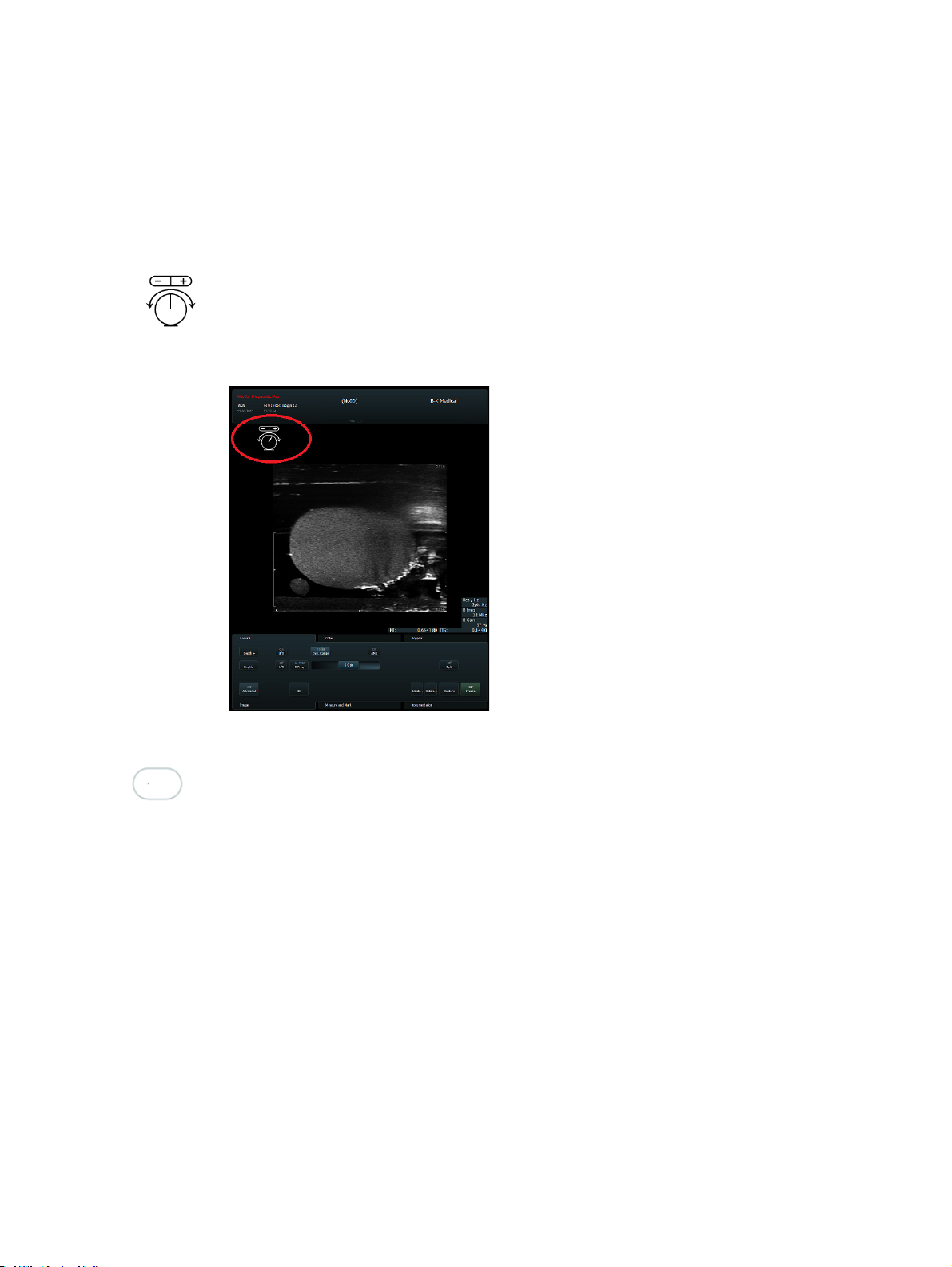
Pos-w1
Before starting an examination, use the ultrasound image to verify that the orientation of
the 2D imaging plane is as indicated on the monitor. If the true imaging plane does not
match the displayed orientation, images may give incorrect information about the anatomy.
WARNING
GS-w4a
It is essential for the patient’s safety that only the correct equipment is used.
•
Do not use other manufacturers’ transducers with BK ultrasound systems.
•
Do not use BK transducers with other manufacturers’ systems.
•
Do not use unauthorized combinations of transducers and needle guides.