GE GEH-ECG 1200 User manual

GE Healthcare
GEH-ECG 1200
User Guide
2102322-111 REV 1
NOTE: The information in this manual only applies to the product GEH-ECG 1200. Due to continuing
product innovation, specifications in this manual are subject to change without notice.
© 2019 General Electric Company. All rights reserved

Symbols
Page 2 2102322-111 REV 1
Copyright © Norav,
No part of this publication may be reproduced in any material
form (including photocopying or storing it in any medium by
electronic means whether or not transiently or incidentally to
some other use of this publication) without the prior written
permission of the copyright owner, or under the terms of a
license issued by the copyright owner.
The information contained in this document is subject to
change without notice. Norav is neither responsible for nor
liable to anyone in connection with this document.
Manufactured by:
Norav Medical Ltd.
4 Hamada st., P.O.Box 81
Yokneam, 2069202 Israel
Telephone: +972 (0) 4-9893001
Faximile: +972 (0) 4-9893004
E-Mail: [email protected]
Distributor:
GE Medical Systems
Information Technologies, Inc.
8200 West Tower Avenue
Milwaukee, WI 53223 USA
Tel.: +1 414 355 5000
1 800 558 5120 (USA only)
MDD authorized representative in Europe is:
Norav Medical GmbH Otto von Guericke Ring 10 D-65205
Wiesbaden Germany
Telephone: +49 (0) 6122-70524-0
Faximile: +49 (0) 6122-70524-14
E-Mail: [email protected]
Disclaimer
This system is intended as a decision support system for
persons who have received appropriate medical training and
should not be used as a sole basis for making clinical
decisions pertaining to patient diagnosis, care, or
management. Any application of medical information from
the program, other than the original design or intended use
thereof, is not advised and considered a misuse of the
software product.
Norav Limited Warranty
Norav products are warranted to be free from manufacturing
and material defects for a period of one (1) year from the date
of shipment from Norav or the dealer to the original
purchaser.
Excluded from this warranty are expendable supply items
including, but not limited to, electrodes, lead wires, patient
cables, and batteries. This warranty does not apply to any
product that Norav determines that it has been modified or
damaged by the customer.
Except for the express warranties stated above, Norav
disclaims all warranties including implied warranties of
merchantability and fitness. The stated express warranties
are in lieu of all obligations or liabilities on the part of Norav
for damages, including but not limited to, special, indirect, or
consequential, arising out of or in connection with the use or
performance of Norav products.
Any action for breach of warranty shall be commenced within
one (1) year of said breach or be forever barred. Any repairs
made to the product that are not covered by the warranty
shall be billed to the customer.
For service or technical support contact GE Healthcare or its
authorized distributor.
GEH-ECG 1200 Recorder conforms to MDD 93/42/EEC and carry the 2797 mark accordingly.
!
Caution
Federal Law restricts this device to sale by or on the order of a licensed
physician or healthcare provider
Document History
Revision
Date
Updates
A
20-Jan-2019
Initial document

Symbols
2102322-111 REV 1 Page 3
Table of contents
Symbols .............................................................................................................................................................. 4
Device Labels...................................................................................................................................................... 4
Warning and Precautions................................................................................................................................... 5
Controls and Indicators...................................................................................................................................... 6
Battery Assembly ............................................................................................................................................... 7
Belt Strap Assembly ........................................................................................................................................... 8
Electrode Application......................................................................................................................................... 8
Patient Leadwires Assembly ........................................................................................................................... 9
Maintenance and Cleaning .............................................................................................................................. 10
Storage ............................................................................................................................................................. 10
Service.............................................................................................................................................................. 11
Calibration........................................................................................................................................................ 11
Troubleshooting............................................................................................................................................... 11
ECG Cables and Accessories............................................................................................................................. 12
Technical Specifications ................................................................................................................................... 12
Electromagnetic Emissions and Immunity Information ................................................................................... 13

Symbols
Page 4 2102322-111 REV 1
Symbols
Symbol
Definition
Warnings call attention to possible hazards involving
potential damage or injury to persons.
!
Cautions refer to practices necessary to protect against
potential damage or loss to equipment. Pay careful
attention to instructions.
NOTE
Notes provide pertinent information to help obtain
optimum performance from the device or signify an
important step or procedure that requires special
attention.
Device Labels
Symbols
Definition
Defibrillation-proof type CF Applied part.
Caution
Refer to operation manual
NOTE On ME EQUIPMENT "Follow
instructions for use”
2797
CE marking
Manufacturer Name and Address
Device Serial Number
Device Reference Number
Date of manufacture
Contains MIC certified RF module
FCC ID:
Contains FCC certified RF module
Contains RCM certified RF module
Disposal of the device in accordance with
the EU Directive 2002/96/EC (WEEE).
Use this battery/accumulator rating

Warning and Precautions
2102322-111 REV 1 Page 5
Warning and Precautions
WARNING
•ELECTROSURGERY
–
There is a risk of burns and injury to the patient. If an electrosurgery device is
used, disconnect the ECG leadwires from the patient.
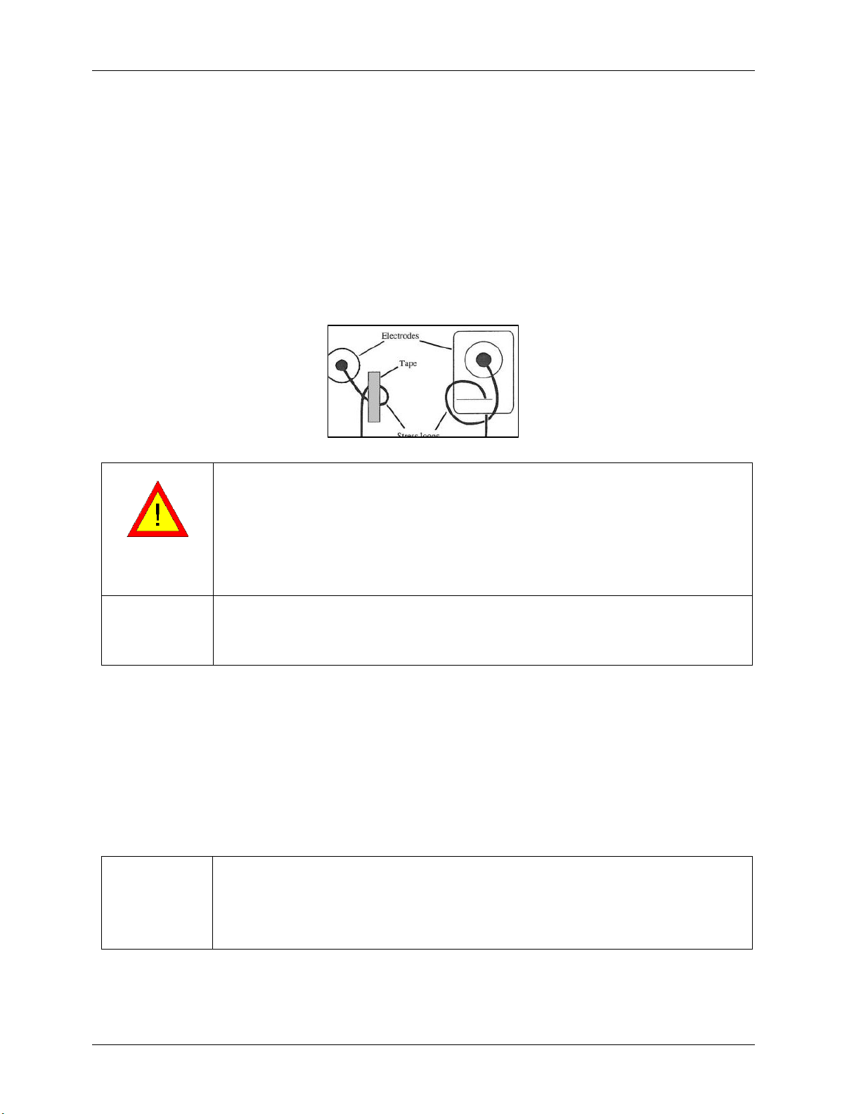
•LEADWIRES –ECG Leadwires present a possible strangulation hazard. To avoid possible strangulation,
route all ECG Leadwires away from patient's throat.
•CONDUCTIVITY –Electric shock or device malfunction may occur if electrodes contact conductive
materials. Keep the conductive parts of lead electrodes and associated parts away from other
conductive parts, including earth. Also make sure that no contact to other conductive parts is possible
if the electrodes loosen during recording.
•GENERAL DANGER TO THE PATIENT –Instructions listed in this manual in no way supersede
established medical practices concerning patient care. Perform the establishedmedical practices
under all circumstances.
•EXPLOSION HAZARD—Do not use in the presence of a flammable anesthetic mixture withair or oxygen
or nitrous oxide.
•DEFIBRILLATION - Device is defibrillation protected when the original Norav Medical patient cable is
used. However, as a safety precaution when possible, remove theelectrodes before defibrillation.
•GENERAL DANGER TO THE PATIENT - The device is not designed for direct cardiac application.
•INFECTION RISK –Reuse of disposable parts that come into contact with patients pose a risk of
infecting patients. Do not reuse disposable parts that have had direct contact with the patient, such as
ECG electrodes.
•INTERPRETATION HAZARD - Computerized interpretation is only significant when used in conjunction
with clinical findings. A qualified physician must over read all computer-generated tracings.
•MAGNETIC AND ELECTRICAL INTERFERENCE - Magnetic and electrical fields are capable of interfering
with the proper performance of the device. For this reason, make sure that all external devices
operated in the vicinity of the device comply with the relevant EMC requirements. X-ray equipment or
MRI devices are possible sources of interference as theymay emit higher levels of electromagnetic
radiation. Ensure that there are no X-ray arrays, MRI or high-performance transformers are near the
device.
•OPERATOR - Medical technical equipment such as this system must only be used by qualified and
trained personnel. Operate the unit only at clinics and hospitals. Do not use at home.
•OPERATION WITH OTHER DEVICES
Other devices which are part of the system must meet the requirements of the Standard for
Information Technology Equipment (IEC/EN 60950-1) and the Standard for Electrical Medical
Devices (IEC/EN 60601-1).
The personal computer should be approved to the appropriate safety standard for non-
medical electrical equipment (IEC/EN 60950-1, or its national variants).
Accessory equipment connected to the analogue and digital interfaces must be certified
according to the respective IEC/EN standards (e.g. IEC/EN 60950-1 for data processing
equipment and IEC/EN 60601-1 for medical equipment). Furthermore, all configurations shall
comply with the valid version of the standard IEC/EN 60601-1. Therefore anybody, who
connects additional equipment to the signal input or output connector to configure a
medical system, must make sure that it complies with the standard.
When using GEH-ECG 1200 in combination with any other equipment, refer to aqualified
service technician for correct handling.
•MIXING UP RECORDINGS –To ensure that a recording is not assigned to the wrong patient DO NOT use
more than one identical marked RF ID pair of 1200W/1200WR at the same wireless environment.
!
Caution
•DAMAGE TO THE DEVICE THROUGH BATTERY LEAKAGE
–
Batteries may leak if left in an unused device
for prolonged periods. If you intend to store the device for longer than one week, remove the battery
from it.
•LEADWIRE DAMAGE –Bending or wrapping the ECG Leadwire can damage it. When attaching and
affixing the ECG leadwire, make sure not to bend it excessively. Avoid coiling the ECG leadwire around
the device, as this can damage the leadwire.
•DAMAGE TO THE DEVICE –You may only open the battery compartment of the patient unit. Do not use
force when handling the recorder.
•SAFETY ONLY WITH APPROVED ACCESSORIES –Safe and reliable operation of the device is only possible
when using the supplied and approved accessories.
•DIFFICULTIES FINDING CAUSES FOR MALFUNCTIONS –To find and repair a malfunction, both device and
ECG leadwires are needed. Remember to include the ECG leadwire when returning the device for
service or repair. (Avoid wrapping the ECG leadwires around the device, as this can damage the
leadwires.) Always use the same ECG leadwires sets with a device. If an institution has several devices
and ECG leadwires sets, try to ensure that each device is matched with a specific ECG leadwires set. In
this way, leadwire or recorder failures can be isolated and eliminated faster. In the event of apparent
changes in the performance of the device, discontinue use immediately. Do not resume use until the
device is approved by the manufacturer or by a representative of the manufacturer.

Controls and Indicators
Page 6 2102322-111 REV 1
•DAMAGE TO DEVICE AND ACCESSORIES
–
Unauthorized personnel do not have the proper training to
repair the device. Repairs carried out by unauthorized personnel could result in damage to the device
or accessories. Send the device for inspection to an authorized facility if you find or even suspect a
malfunction. Please add a detailed description of the observed malfunction.
•DAMAGE TO THE DEVICE –Take care to prevent chemicals\liquids from entering the connectors or
internal part of the device.
•PACEMAKER - It is recommended that a minimum separation of 15 cm (6 inches) be maintained
between the wireless patient unit 1200W and a pacemaker to avoid potential interference with
pacemaker. Some studies have shown that wireless devices might interfere with implanted cardiac
pacemakers if used within eight inches of the pacemaker. Pacemaker users may want to avoid placing
or using a wireless device this close to their pacemaker. If you have any reason to suspect that
interference is taking place, turn off the ECG immediately.
!
Caution
Use only while patient unit 1200W is worn on patient with its strap.
Use only with battery compartment of patient unit 1200W is closed.
NOTE
•The GEH-ECG 1200 complies with Part 15 of the FCC Rules. Operation is subject to the following two
conditions:
This device may not cause harmful interference and
This device must accept any interference received, including interference that may cause
undesired operation.
•The manufacturer is not responsible for any Radio or TV interference caused by unauthorized
modifications to this equipment. Such modifications could void the user’s authority to operate the
equipment.
NOTE
NO OPTIMUM WIRELESS PERFOMANCE
Note that the complete data transfer cannot be guaranteed under all circumstances when using Norav
proprietary RF technology and that range loss can occur if this technology and other RF Devices (Bluetooth,
WLAN.) are used near each other. Also, other devices could interfere with the equipment, even if the other
devices comply with CISPR emission requirements
In case of interruptions with the Norav proprietary RF technology:
•Remove any objects from the line of sight between patient acquisition unit 1200W and Receiver
unit 1200WR
•Remove any possible RF interfering devices from the vicinity of 1200W and 1200WR.
•Do not position the devices closer than 50cm to each other or more than 10m from each other.
Controls and Indicators
Element
Description
1
Patient unit 1200W – Power ON/OFF Button
2
Patient unit 1200W – Low Battery indicator
3
Patient unit 1200W – Power ON/OFF indicator. Transmit/Standby indicator
4
Patient unit 1200W – Detachable ECG Leadwires
5
Patient unit 1200W – Leadwires guides. Strap Holders.
6
Patient unit 1200W –
Battery compartment door
7
Receiver unit 1200WR – Detachable RF Antenna
8
Receiver unit 1200WR – Power ON/OFF indicator.
9
Receiver unit 1200WR – Detachable USB Cable
10
Receiver unit 1200WR – Auxiliary BNC output

Battery Assembly
2102322-111 REV 1 Page 7
Battery Assembly
(1) Insert the first battery and slide it to the right.
(2) Insert the second battery and push it to the left and down with the same movement.
(3) Place the battery cover.
(4) Push battery cover down until get click.
!
Caution
•Do not leave battery in the recorder for extended periods (more than two weeks) when the recorder
is not in use.
•If you use rechargeable batteries, the battery recharger should be kept out ofthe patient
environment and hook-up area.
•Dispose of used batteries carefully, using environmentally friendly methods wherever possible
following the state’s recycling laws or your facility’srecycling policy
•Use only the recommended battery type as instructed in the technical specifications to operate the
1200W device (AA size Alkaline or NiMH rechargeable batteries).
•Do not use batteries with expired dates.

Belt Strap Assembly
Page 8 2102322-111 REV 1
Belt Strap Assembly
1. Take the end of the strap (ensuring there are no twists present), thread the strap via strap
holders of the 1200W.
2. Take the end of the strap and the end of the buckle with center bar and then thread the strap
from the bottom side of the buckle up between the main body of the buckle and the innermost
side of the center bar.
3. Pass the strap over the top side of the bar, and thread it back down between the inner bar and
the outermost bar. This is the end of the buckle that allows you to adjust the length of the
strap if needed.
Electrode Application
NOTE
Many ECG adhesive electrodes are suitable for use. As ECG electrodes from different manufacturers have
different electrical properties, the choice of ECG electrodes can considerably affect the measurement
results and quality. Ensure that only high-quality electrodes are used.
Wet gel electrodes are recommended.
Always refer to the ANSI/AAMI EC12:2000 Standard for safety, performance, and labeling requirements for
the disposable electrodes, and guidelines for reliable patient connections.
Prepare the patient’s skin prior to applying the electrodes. Skin is a poor conductor of electricity, so skin
preparation is important in achieving good electrode-to-skin contact.
•If necessary, clip hair at the electrode sites (or shave sites, if needed).
•Clean and abrade the skin at the electrode sites to remove oil and dead skin.
•Wash the skin thoroughly with soap and water.
•Dry the electrode placement sites.

Patient Leadwires Assembly
2102322-111 REV 1 Page 9
Attaching the Electrodes
•
Attach the leads to the electrodes before placing them on the patient.
•
Apply the electrodes by peeling them, one at a time, from the protective backing and
stickingthem firmly to the patient’s skin.
•
The electrodes should be placed over bone at each of the sites.
•
The offset connector tab should be positioned in the same direction as the lead wires,
towardsthe equipment.
•
Place the electrode on the skin by gently pressing around the edge. For wet gel always
avoidpressing down the centre of the electrode. If in doubt refer to the directions on the
reverse of thepouch.
If you use lead lock or clip lock electrodes, be sure to use the lock or clip to relieve stress on each lead wire.
Otherwise, tape each lead wire into a stress loop to help prevent movement of the electrode.
WARNING
As you attach electrodes, be careful to not let any unattached electrode come incontact with other
conductive objects, including ground.
Leave 1.5 meters (5 feet) of open area around the patient during recorder hookupand removal.
Do not connect external devices to the recorder. Connect patient lead wires only tothe patient electrodes
Keep the recorder and patient cable clean, especially the components that touchpatients.
Do not use electrodes for adults on children.
Before each recording and before attaching sensors or electrodes to the patient, check the casing and the
ECG patient leadwires for damage which may have occurred, for example, due to mechanical overload,
falling from a great height or wear and tear (chafed patches on the cable). Do not use the instrument or
the leadwires if you detect cracks, melted areas or any other signs of damage to the leadwires or housing.
!
Caution
Verify that dates on applicable accessories have not expired.
ECG electrodes can cause skin irritation. Examine the skin for signs of irritation or inflammation and avoid
placement of the electrode in those areas. If skin irritation occurs during the procedure advise the patient
to remove the electrodes and contact the health service provider as soon as possible.
Patient Leadwires Assembly
This Leadwires set is intended to be used for the hook-up of a patient to an electromedical device with the
purpose of sensing electrocardiography signals from the human skin using appropriate disposable or
reusable ECG electrodes. The application must be performed by a skilled medical professional. Use the
patient cable only as it is intended.
Insert the Patient ECG leadwire connector into ECG leadwire connector slot of the 1200W unit, as shown on
the picture. Make sure that marking of leadwires are the same as marking on the slot connector
!
Caution
Be careful not to connect the Patient ECG leadwire connector upside down or atan angle into the ECG
leadwire slot on the 1200W unit. This may result in damage to both the Leadwire connector and the ECG
leadwire input slot of the unit.
During recording, make sure that the lead wires are not caught by the movingparts of a machine or sport
equipment. This could lead to damage or injury (e.g. if loops are formed in the lead wires).
NEVER pull on the leadwire itself because this can easily break the wire insidethe insulation. Pulling on the
cable also can cause a noisy and intermittent ECG recording.

Maintenance and Cleaning
Page 10 2102322-111 REV 1
Maintenance and Cleaning
Remove the battery before cleaning the 1200W recorder. To clean the recorder unit and ECG lead wires,
wipe with a dry cloth or a cloth soaked with regular household cleaner diluted with water.
!
Caution
Take care to prevent chemicals\liquids from entering the connectors or internal part of the recorder.
The battery contacts should not come in contact with soap or water.
Do not polish the housing with abrasive or chemical cleanser.
Use of alcohol, acetone, Alkyl Dimethyl Benzyl ammonium chlorides or a methyl ammonium chloride is
NOT recommended to clean the reorder unit and holster. Use of alcohol or acetone on lead wires could
cause the lead wires to stiffen and theinsulating plastic to crack. Use of a methyl ammonium chloride
(commonly found in many consumer wipes) on the recorder unit and holster could cause the plastic to
deteriorate.
The recorder and patient leadwires must not be autoclaved or sterilized with steam.
NOTE
If liquid penetrates the device, i.e. during cleaning or recording, this may interfere with correct
functioning. Switch the recorder OFF and remove the battery. Leave the recorder in a warm, dry room
with the battery door open for 48 hours. If the functioning is still affected, contact the contact customer
support.
Before using the 1200W recorder, execute the check of the unit in accordance with the check procedure. In
case that any rejected items are found as a result of the check, it will be totally judged as rejection. Take
the corrective measures as the rejected items. Use the recorder after all the items become accepted.
Unit check shall be performed by each medical institution, or by Norav personnel, representative agent, or
an authorized third party. For more details, do not hesitate to consult your dealer or Norav Medical
personnel.
Details of the check
Check Method
Criteria
Operation manual
Check that the operation manual is
kept in a predetermined place.
Should be kept in a
predetermined
place.
Cracks and distortion of the recorder
enclosure
Visually check the recorder enclosure
for cracks and distortion.
Must be free from cracks and
distortion.
Cracks and distortion of
the Leadwires
Visually check the ECG Leadwires for
cracks and distortion.
Must be free from cracks and
distortion.
Battery compartment
Check whether dirt or hair is not
accumulated between the battery
compartment and its door
Must be free from dirt or
hair.
Keypad Power button
Check whether the keypad button
have tactile feedback when pressed
Must get tactile feedback.
Battery contacts in the battery
compartment
Visually check the battery contacts for
strain, skew, and corrosion.
Must be free from strain,
skew, and
corrosion.
Storage
Before storage, make sure to remove the batteries from the 1200W recorder and close the battery
compartment door tightly. Store the recorder in the provided storage carton case.
!
Caution
•Store the 1200W recorder in an area free from water or humidity
•Take care to avoid areas subject to high humidity, poor ventilationand direct sunlight; store the
1200W recorder in an area free from any adverse effects of surrounding air containing dust, sodium,
andsulfur.
•Do not store the 1200W recorder in an area where chemicals are kept, or which is exposed to
chemical fumes or vapors.

Service
2102322-111 REV 1 Page 11
Service
If there is a problem with the 1200W recorder, review the Troubleshooting section for a listing of problems
and solutions. If additional assistance is required, contact customer support via phone, fax or e-mail listed
in this manual. Call customer support before returning a recorder to make shipping arrangements.
All repairs on products under warranty must be performed or approved by Norav Medical. Unauthorized
repairs void the warranty. In addition, whether or not covered under warranty, any product repair shall
exclusively be performed by Norav Medical certified service personnel.
When calling, please be prepared to provide:
•Product name and complete description of the problem.
•Serial number of your product.
In case a return cannot be avoided, the representative will record all necessary information and will
provide a Return Material Authorization (RMA) number, as well as the appropriate return address. An RMA
number must be obtained prior to any return.
If you have to return goods for service, follow these recommended packing instructions:
•Remove all cables, sensors, and ancillary products (as appropriate) before packing, unless you suspect
they are associated with the problem.
•Wherever possible use the original shipping carton and packing materials.
•Include a packing list and the Norav Return Material Authorization (RMA) number.
It is recommended that all returned goods be insured. Claims for loss or damage to the product must be
initiated by the sender.
Calibration
The device does not need any calibration.
Troubleshooting
Symptom
Solution
Recorder does not power on
•Ensure batteries are inserted with correct polarity.
•Install a new AA battery.
Low battery indicator
•Install a new AA battery.
•
Inspect battery compartment, clean contacts if necessary.
Lead OFF
(message on Host system)
•Ensure patient leadwire is connected to the recorder.
•Check that the recorder sided connector is not damaged.
•Check that the Leadwire connector pins are not broken or bent /
damaged.
•Ensure you have prepared the patient’s skin according to the
instructions.
•Ensure the electrodes are properly applied to the patient.
•Ensure the leads are making proper contact with the electrodes.
•Replace the Patient ECG Leadwires.
Noise artifacts on ECG signal
•Ensure you have prepared the patient’s skin according to the
instructions.
•Ensure the electrodes are properly applied to the patient.
•Ensure the leads are making proper contact with the electrodes.
•Replace the Patient ECG Leadwires.

ECG Cables and Accessories
Page 12 2102322-111 REV 1
ECG Cables and Accessories
Accessories
Part Number
Leadwires with Snaps IEC
2102322-011
Leadwires with Snaps AHA
2102322-012
Leadwires with Clips IEC
2102322-013
Leadwires with Clips AHA
2102322-014
Black belt for 1200W acquisition unit
2102322-015
USB cable 3m for 1200WR Receiver
2102322-053
BNC cable 3m for 1200WR Receiver
2102322-054
Technical Specifications
1200W (Acquisition unit)
ECG
Lead system
Standard 12 Lead
Patient Leads
Detachable 10 Lead wires conform to AAMI
Defibrillation protection
Protected against 360J discharge
Patient leakage current
< 10 uA
Input impedance
> 10 MOhm
CMMR
> 90dB
Frequency range
0.05 – 150Hz
Dynamic range
+/- 2.4V
Resolution
24 bits (0.286 uV/LSB)
Sample Rate Internal
8000
Sample Rate Recording
500
Lead OFF Detection
Yes
Communication
Digital RF
2400 – 2483 MHz,
0.4mW, conform to FCC Part 15.249
Power
Battery
Size AA x 2, Alkaline or NiMH
Operation time
Up to 40 hours with Alkaline Batteries
Mechanical
Size
140 x 95 x 50 mm
Weight
350g
Environmental
Operating Temp. Range
10 to 40 °C
Storage Temp. Range
-20 to 60 °C
Relative Humidity
10 to 95 % (non-condensing)
1200WR (Receiver)
Auxiliary output
ECG Out Bandwidth (-3db)
0.5 to 150 Hz
ECG Out Gain
1000
ECG Out Sample Rate
500
TTL Trigger width
16-128ms
TTL Trigger delay
<11ms (delay from R-wave)
Communication
USB
USB2.0 Full Speed
Digital RF
2400 – 2483 MHz,
0.4mW, conform to FCC Part 15.249
Power
USB 5V
100mA max at 5V input
Mechanical
Size
100 x 54 x 30 mm
Weight
80g
Environmental
Operating Temp. Range
10 to 40 °C
Storage Temp. Range
-20 to 60 °C
Relative Humidity
10 to 95 % (non-condensing)
Regulatory
Safety Standards
IEC 60601-1, 60601-1-2, 60601-2-25
Classification
Type CF with defibrillation proof. Internally powered
Certification
CE, FDA

Electromagnetic Emissions and Immunity Information
2102322-111 REV 1 Page 13
Electromagnetic Emissions and Immunity Information
Refer to the following tables for specific information regarding NR recorder compliance to IEC 60601-1-2.
Table 1: Electromagnetic Emissions
Emissions Test
Compliance
Electromagnetic Environment—Guidance
This device is intended for use in the electromagnetic environment specified below.
The customer and/or user of this device should ensure that it is used in such an environment.
RF Emissions CISPR 11
Group 2
This device must emit electromagnetic energy in order to perform its
intended function. Nearby electronic equipment may be affected.
RF Emissions CISPR 11
Class B
This device is suitable for use in all establishments, including domestic and
those directly connected to the public low
-voltage power supply network
that supplies buildings used for domestic purposes.
Harmonic Emissions IEC 61000-3-2
N/A
Voltage Fluctuations/Flicker Emissions
IEC 61000-3-3
N/A
Table 2: Electromagnetic Immunity
Immunity Test
IEC 60601 Test Level
Compliance
Level
Electromagnetic Environment—Guidance
This device is intended for use in the electromagnetic environment specified below.
The customer and/or user of this device should ensure that it is used in such an environment.
Electrostatic Discharge
(ESD) IEC
61000-4-2
±6 kV contact
±8 kV air
±6 kV contact
±8 kV air
Floors should be wood, concrete, or ceramic tile. If
floors are covered with synthetic material, relative
humidity should be at least 30%.
Electrical Fast
Transient/Burst IEC 61000
-
4-4
±2 kV for power supply lines
±1 kV for input/output lines
N/A
Mains power quality should be that of a typical
commercial or hospital environment.
Surge
IEC 61000-4-5
±1 kV differential mode
±2 kV common mode
N/A
Mains power quality should be that of a typical
commercial or hospital environment.
Voltage dips, short
interruptions, and voltage
variations on power supply
input lines
IEC 61000
-4-11
±5% UT (>95% dip in UT) for 0.5
cycle
±40% UT (60% dip in UT) for 5
cycles
±70% UT (30% dip in UT) for 25
cycles
<5% UT (>95% dip in UT) for 5 sec.
N/A
Mains power quality should be that of a typical
commercial or hospital environment.
Power Frequency
(50/60 Hz) Magnetic Field
IEC 61000-4-8
3 A/m
3 A/m
Power frequency magnetic fields should be at levels
characteristic of
a typical location in a typical
commercial or hospital environment.
NOTE: UT is the AC mains voltage before application of the test level.
Table 3: Guidance and Manufacturer’s Declaration—Electromagnetic Immunity
Immunity Test
IEC 60601 Test Level
Compliance
Level
Electromagnetic Environment—Guidance
This device is intended for use in the electromagnetic environment specified below.
The customer and/or user of this device should ensure that it is used in such an environment.
Portable and mobile RF communications equipment should be used no closer to any part of the device, including cables, than the
recommended separation distance calculated from the equation applicable to the frequency of the transmitter.
Conducted RF
3 Vrms
3 Vrms
Recommended Separation Distance
80 MHz to 800 MHz
800 MHz to 2.5 GHz
where P is the maximum output power rating of the transmitter in watts (W)
according to the transmitter manufacturer and
dis the
recommended separation distance in meters (m).
Field
strengths from fixed RF transmitters, as determined by an
electromagnetic site survey
; should be less than the compliance level in each
frequency range
ᵇ.
Interference may occur in the vicinity of equipment marked with the
following symbol:
IEC 61000-4-6
150 kHz to 80 MHz
Radiated RF
3 V/m
3 V/m
IEC 61000-4-3
80 MHz to 2.5 GHz
a. Field strengths from fixed transmitters, such as base stations for radio (cellular/cordless) telephones and land mobile

Electromagnetic Emissions and Immunity Information
Page 14 2102322-111 REV 1
radios, amateur radio, AM and FM radio broadcast and TV broadcast cannot be predicted theoretically with accuracy. To
assess the electromagnetic environment due to fixed RF transmitters, an electromagnetic site survey should be
considered. If the measured field strength in the location in which the device is used exceeds the applicable RF compliance
level above, the device should be observed to verify normal operation. If abnormal performance is observed, additional
measures may be necessary, such as reorienting or relocating the device
b. Over the frequency range 150 kHz to 80 MHz, field strengths should be less than [3] V/m.
NOTES:
•At 80 MHz and 800 MHz, the higher frequency range applies.
•These guidelines may not apply in all situations. Electromagnetic propagation is affected by absorption and reflection from
structures, objects, and people.
Table 4: Recommended Separation Distances
The following table details the recommended separation distances between portable and mobile RF communications equipment and
NR recorder.
This device is intended for use in an electromagnetic environment in which radiated RF disturbances are controlled. Users of this
device can help prevent electromagnetic interference by maintaining a minimum distance between portable and mobil
e RF
communication equipment (transmitters) and the device as recommended below, according to maximum output power of the
communications equipment.
Separation Distance According to Frequency of Transmitter(m)
Rated Maximum Output Power of
Transmitter
W
150 kHz to 80 MHz
80 MHz to 800 MHz
800 MHz to 2.5 GHz
0.01
0.12
0.12
0.23
0.1
0.37
0.37
0.74
1
1.2
1.2
2.3
10
3.7
3.7
7.4
100
12
12
23
For transmitters rated at a maximum output power not listed above, the recommended separation distance d in meters (m) can be
estimated using the equation applicable to the frequency of the transmitter, where P is the maximum output power rating of the
transmitter in watts (W) according to the transmitter manufacturer.
NOTES:
At 80 MHz and 800 MHz, the higher frequency range applies.
These guidelines may not apply in all situations. Electromagnetic propagation is affected by absorption and reflection from
structures, objects, and people.

Electromagnetic Emissions and Immunity Information
2102322-111 REV 1 Page 15
Table of contents
Other GE Medical Equipment manuals