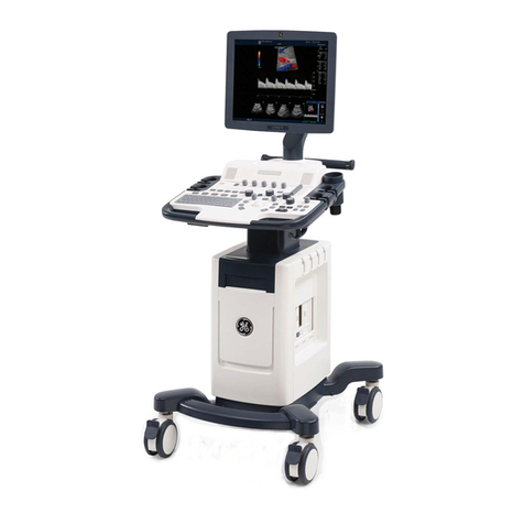
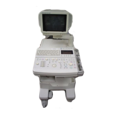
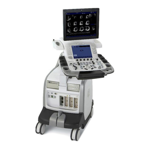
GE LOGIQ 100 PRO User manual

Technical
Publication
GE Healthcare
Direction 5305880-100
Revision 3
GE Healthcare
LOGIQ™ 100 PRO Service Manual
Copyrighted©1995-2008 by General Electric Co.
All Rights Reserved.
State:RELEASE-DocumentisreleasedandunderformalChangeControl.ChangesaresubjecttotheECR/ECOProcess.
SeetheGEHCMyworkshopSystemtodeterminethestatusofthisdocument.
ApprovedDocument-5305880-100TPH_r3.pdfPage2of197

GE HEALTHCARE
DIRECTION 5305880-100 , REVISION 3 LOGIQ™ 100 PRO SERVICE MANUAL
Page i-ii -
Your Notes:
State:RELEASE-DocumentisreleasedandunderformalChangeControl.ChangesaresubjecttotheECR/ECOProcess.
SeetheGEHCMyworkshopSystemtodeterminethestatusofthisdocument.
ApprovedDocument-5305880-100TPH_r3.pdfPage3of197

GE HEALTHCARE
DIRECTION 5305880-100, REVISION 3 LOGIQ™ 100 PRO SERVICE MANUAL
- Page i-i
IMPORTANT PRECAUTIONS
LANGUAGE
• THIS SERVICE MANUAL IS AVAILABLE IN ENGLISH ONLY.
• IF A CUSTOMER’S SERVICE PROVIDER REQUIRES A LANGUAGE OTHER
THAN ENGLISH, IT IS THE CUSTOMER’S RESPONSIBILITY TO PROVIDE
TRANSLATION SERVICES.
• DO NOT ATTEMPT TO SERVICE THE EQUIPMENT UNLESS THIS SERVICE
MANUAL HAS BEEN CONSULTED AND IS UNDERSTOOD.
• FAILURE TO HEED THIS WARNING MAY RESULT IN INJURY TO THE SERVICE
PROVIDER, OPERATOR OR PATIENT FROM ELECTRIC SHOCK,
MECHANICAL OR OTHER HAZARDS.
• CE MANUEL DE MAINTENANCE N’EST DISPONIBLE QU’EN ANGLAIS.
• SI LE TECHNICIEN DU CLIENT A BESOIN DE CE MANUEL DANS UNE AUTRE
LANGUE QUE L’ANGLAIS, C’EST AU CLIENT QU’IL INCOMBE DE LE FAIRE
TRADUIRE.
• NE PAS TENTER D’INTERVENTION SUR LES ÉQUIPEMENTS TANT QUE LE
MANUEL SERVICE N’A PAS ÉTÉ CONSULTÉ ET COMPRIS.
• LE NON-RESPECT DE CET AVERTISSEMENT PEUT ENTRAÎNER CHEZ LE
TECHNICIEN, L’OPÉRATEUR OU LE PATIENT DES BLESSURES DUES À DES
DANGERS ÉLECTRIQUES, MÉCANIQUES OU AUTRES.
• DIESES KUNDENDIENST-HANDBUCH EXISTIERT NUR IN ENGLISCHER
SPRACHE.
• FALLS EIN FREMDER KUNDENDIENST EINE ANDERE SPRACHE BENÖTIGT,
ISTESAUFGABEDESKUNDEN FÜREINEENTSPRECHENDE ÜBERSETZUNG
ZU SORGEN.
• VERSUCHEN SIE NICHT, DAS GERÄT ZU REPARIEREN, BEVOR DIESES
KUNDENDIENST-HANDBUCH NICHT ZU RATE GEZOGEN UND VERSTANDEN
WURDE.
• WIRD DIESE WARNUNG NICHT BEACHTET, SO KANN ES ZU
VERLETZUNGENDESKUNDENDIENSTTECHNIKERS,DESBEDIENERSODER
DES PATIENTEN DURCH ELEKTRISCHE SCHLÄGE, MECHANISCHE ODER
SONSTIGE GEFAHREN KOMMEN.
WARNING
AVERTISSEMENT
WARNUNG
State:RELEASE-DocumentisreleasedandunderformalChangeControl.ChangesaresubjecttotheECR/ECOProcess.
SeetheGEHCMyworkshopSystemtodeterminethestatusofthisdocument.
ApprovedDocument-5305880-100TPH_r3.pdfPage4of197

GE HEALTHCARE
DIRECTION 5305880-100, REVISION 3 LOGIQ™ 100 PRO SERVICE MANUAL
Page i-ii -
• ESTE MANUAL DE SERVICIO SÓLO EXISTE EN INGLÉS.
• SI ALGÚN PROVEEDOR DE SERVICIOS AJENO A GEMS SOLICITA UN IDIOMA
QUE NO SEA EL INGLÉS,ES RESPONSABILIDAD DEL CLIENTE OFRECER UN
SERVICIO DE TRADUCCIÓN.
• NO SE DEBERÁ DAR SERVICIO TÉCNICO AL EQUIPO, SIN HABER
CONSULTADO Y COMPRENDIDO ESTE MANUAL DE SERVICIO.
• LA NO OBSERVANCIA DEL PRESENTE AVISO PUEDE DAR LUGAR A QUE EL
PROVEEDOR DE SERVICIOS, EL OPERADOR O EL PACIENTE SUFRAN
LESIONES PROVOCADAS POR CAUSAS ELÉCTRICAS, MECÁNICAS O DE
OTRA NATURALEZA.
• ESTE MANUAL DE ASSISTÊNCIA TÉCNICA SÓ SE ENCONTRA DISPONÍVEL
EM INGLÊS.
• SE QUALQUER OUTRO SERVIÇO DE ASSISTÊNCIA TÉCNICA, QUE NÃO A
GEMS, SOLICITAR ESTES MANUAIS NOUTRO IDIOMA, É DA
RESPONSABILIDADE DO CLIENTE FORNECER OS SERVIÇOS DE
TRADUÇÃO.
• NÃO TENTE REPARAR O EQUIPAMENTO SEM TER CONSULTADO E
COMPREENDIDO ESTE MANUAL DE ASSISTÊNCIA TÉCNICA.
• O NÃO CUMPRIMENTO DESTE AVISO PODE POR EM PERIGO A SEGURANÇA
DO TÉCNICO, OPERADOR OU PACIENTE DEVIDO A‘ CHOQUES ELÉTRICOS,
MECÂNICOS OU OUTROS.
• IL PRESENTE MANUALE DI MANUTENZIONE È DISPONIBILE SOLTANTO IN
INGLESE.
• SE UN ADDETTO ALLA MANUTENZIONE ESTERNO ALLA GEMS RICHIEDE IL
MANUALE IN UNA LINGUA DIVERSA, IL CLIENTE È TENUTO A PROVVEDERE
DIRETTAMENTE ALLA TRADUZIONE.
• SIPROCEDA ALLAMANUTENZIONE DELL’APPARECCHIATURA SOLO DOPO
AVER CONSULTATO IL PRESENTE MANUALE ED AVERNE COMPRESO IL
CONTENUTO.
• NON TENERE CONTO DELLA PRESENTE AVVERTENZA POTREBBE FAR
COMPIERE OPERAZIONI DA CUI DERIVINO LESIONI ALL’ADDETTO ALLA
MANUTENZIONE, ALL’UTILIZZATORE ED AL PAZIENTE PER
FOLGORAZIONE ELETTRICA, PER URTI MECCANICI OD ALTRI RISCHI.
AVISO
ATENÇÃO
AVVERTENZA
State:RELEASE-DocumentisreleasedandunderformalChangeControl.ChangesaresubjecttotheECR/ECOProcess.
SeetheGEHCMyworkshopSystemtodeterminethestatusofthisdocument.
ApprovedDocument-5305880-100TPH_r3.pdfPage5of197

GE HEALTHCARE
DIRECTION 5305880-100, REVISION 3 LOGIQ™ 100 PRO SERVICE MANUAL
- Page i-iii
State:RELEASE-DocumentisreleasedandunderformalChangeControl.ChangesaresubjecttotheECR/ECOProcess.
SeetheGEHCMyworkshopSystemtodeterminethestatusofthisdocument.
ApprovedDocument-5305880-100TPH_r3.pdfPage6of197

GE HEALTHCARE
DIRECTION 5305880-100, REVISION 3 LOGIQ™ 100 PRO SERVICE MANUAL
Page i-iv -
DAMAGE IN TRANSPORTATION
All packages should be closely examined at time of delivery. If damage is apparent write “Damage
In Shipment” on ALL copies of the freight or express bill BEFORE delivery is accepted or “signed
for” by a GE representative or hospital receiving agent. Whether noted or concealed, damage
MUST be reported to the carrier immediately upon discovery, or in any event, within 14 days after
receipt, and the contents and containers held for inspection by the carrier. A transportation
company will not pay a claim for damage if an inspection is not requested within this 14 day period.
CERTIFIED ELECTRICAL CONTRACTOR STATEMENT - FOR USA ONLY
All electrical installations that are preliminary to positioning of the equipment at the site prepared for
the equipment shall be performed by licensed electrical contractors. Other connections between
peices of electrical equipment, calibrations and testing shall be performed by qualified GE Medical
Systems personnel. In performing all electrical work on these products, GE will use its ownspecially
trained filed engineers. All of GE’s electrical work on these products will comply with the
requirements of the applicable electrical codes.
The purchaser of GE equipment shall only utilize qualified personnel (i.e., GE’s field engineer’s,
personnel of third party service companies with equivalent training, or licensed electricians ) to
perform electrical servicing on the equipment.
OMISSIONS & ERRORS
If there are any omissions, errors or suggestions for improving this documentation, please contact
the GE Medical Systems Global Documentation Group with specific information listing the system
type, manual title, part number, revision number, page number and suggestion details. Mail the
information to : Service Documentation, 9900 Innovation Drive (RP-2123), Wauwatosa, WI 53226.
, USA.
GE Medical Systems employees should use the iTrack System to report all documentation errors
or omisions.
State:RELEASE-DocumentisreleasedandunderformalChangeControl.ChangesaresubjecttotheECR/ECOProcess.
SeetheGEHCMyworkshopSystemtodeterminethestatusofthisdocument.
ApprovedDocument-5305880-100TPH_r3.pdfPage7of197


GE HEALTHCARE
DIRECTION 5305880-100, REVISION 3 LOGIQ™ 100 PRO SERVICE MANUAL
- Page i-v
LEGAL NOTES
The contents of this publication may not be copied or duplicated in any form, in whole or in part,
without prior written permission of GE Medical Systems.
GE Medical Systems may revise this publication from time to time without written notice.
TRADEMARKS
All products and their name brands are trademarks of their respective holders.
COPYRIGHTS
All Material Copyright©1997-2007 by General Electric Inc. All Rights Reserved.
State:RELEASE-DocumentisreleasedandunderformalChangeControl.ChangesaresubjecttotheECR/ECOProcess.
SeetheGEHCMyworkshopSystemtodeterminethestatusofthisdocument.
ApprovedDocument-5305880-100TPH_r3.pdfPage8of197

GE HEALTHCARE
DIRECTION 5305880-100, REVISION 3 LOGIQ™ 100 PRO SERVICE MANUAL
Page i-vi -
State:RELEASE-DocumentisreleasedandunderformalChangeControl.ChangesaresubjecttotheECR/ECOProcess.
SeetheGEHCMyworkshopSystemtodeterminethestatusofthisdocument.
ApprovedDocument-5305880-100TPH_r3.pdfPage9of197

GE HEALTHCARE
DIRECTION 5305880-100, REVISION 3 LOGIQ™ 100 PRO SERVICE MANUAL
- Page i-v
Revision History
Revision Date Reason for change
1JAN 26 2008 Preliminary Release.
2APRIL 24 2008 Changes incorporated for correcting the SPR’s raised against DOC0421436.
3August 4 2008 Changes incorporated on contact details and added additional information based on service
teams requirements.
State:RELEASE-DocumentisreleasedandunderformalChangeControl.ChangesaresubjecttotheECR/ECOProcess.
SeetheGEHCMyworkshopSystemtodeterminethestatusofthisdocument.
ApprovedDocument-5305880-100TPH_r3.pdfPage10of197

GE HEALTHCARE
DIRECTION 5305880-100, REVISION 3 LOGIQ™ 100 PRO SERVICE MANUAL
Page i-vi -
State:RELEASE-DocumentisreleasedandunderformalChangeControl.ChangesaresubjecttotheECR/ECOProcess.
SeetheGEHCMyworkshopSystemtodeterminethestatusofthisdocument.
ApprovedDocument-5305880-100TPH_r3.pdfPage11of197

GE HEALTHCARE
DIRECTION 5305880-100, REVISION 3 LOGIQ™ 100 PRO SERVICE MANUAL
Table Of Contents Page TOC-1
Table Of Contents
Chapter Table Of Contents
Chapter 1 Introduction
Section 1-1Overview ....................................................................................... 1-1
1-1-1 Overview........................................................................................................................ 1-1
1-1-2 Purpose of Chapter 1..................................................................................................... 1-1
1-1-3 Purpose of Service Manual............................................................................................ 1-1
1-1-4 Typical Users of the Basic Service Manual............................................................... 1-2
1-1-5 LOGIQ™ 100 PRO Models Covered by this Manual .................................................... 1-2
1-1-6 Purpose of Operator Manual(s) ..................................................................................... 1-2
Section 1-2 Safety .......................................................................................... 1-3
1-2-1 Warnings........................................................................................................................ 1-3
Section 1-3 Important Conventions.............................................................. 1-4
1-3-1 Conventions Used in Book ............................................................................................ 1-4
1-3-2 Standard Hazard Icons.................................................................................................. 1-5
1-3-3 Product Icons................................................................................................................. 1-6
Section 1-4Safety Considerations .............................................................. 1-10
1-4-1 Introduction.................................................................................................................. 1-10
1-4-2 Human Safety.............................................................................................................. 1-10
1-4-3 Mechanical Safety ...................................................................................................... 1-11
1-4-4 Electrical Safety........................................................................................................... 1-11
1-4-5 Labels Locations.......................................................................................................... 1-12
1-4-6 Dangerous Procedure Warnings ................................................................................. 1-18
1-4-7 Lockout/Tagout Requirements (For USA Only)........................................................... 1-18
1-4-8 Classification................................................................................................................ 1-18
Section 1-5 EMC, EMI, and ESD............................................................... 1-19
1-5-1 Electromagnetic Compatibility (EMC).......................................................................... 1-19
1-5-2 CE Compliance............................................................................................................ 1-19
1-5-3 EMC Performance ....................................................................................................... 1-19
1-5-4 Notice Upon Installation of Product ............................................................................. 1-19
1-5-5 General Notice............................................................................................................. 1-20
1-5-6 Countermeasures against EMC related Issues........................................................... 1-20
1-5-7 Notice on Service......................................................................................................... 1-20
1-5-8 Electrostatic Discharge (ESD) Prevention................................................................... 1-21
Section 1-6Customer Assistance ................................................................ 1-21
1-6-1 System Manufacturer................................................................................................... 1-21
1-6-2 Contact Information ..................................................................................................... 1-22
Chapter 2 Pre Installation
Section 2-1Overview ....................................................................................... 2-1
2-1-1 Purpose of Chapter 2..................................................................................................... 2-1
Section 2-2 General Console Requirements................................................. 2-1
2-2-1 Console Environmental Requirements .......................................................................... 2-1
State:RELEASE-DocumentisreleasedandunderformalChangeControl.ChangesaresubjecttotheECR/ECOProcess.
SeetheGEHCMyworkshopSystemtodeterminethestatusofthisdocument.
ApprovedDocument-5305880-100TPH_r3.pdfPage12of197

GE HEALTHCARE
DIRECTION 5305880-100, REVISION 3 LOGIQ™ 100 PRO SERVICE MANUAL
Page TOC-2
Lighting 2
2-2-2 Electrical Requirements ................................................................................................ 2-2
2-2-2-1 LOGIQ™ 100 PRO Power Requirements......................................................... 2-2
2-2-2-2 Site Circuit Breaker ........................................................................................... 2-2
2-2-2-3 Site Power Outlets............................................................................................. 2-2
2-2-2-4 Unit Power Plug................................................................................................. 2-2
2-2-2-5 Power Stability Requirements........................................................................... 2-2
2-2-3 EMI Limitations 2-3
2-2-4 Probes Environmental Requirements ............................................................................ 2-4
2-2-5 Time and Manpower Requirements............................................................................... 2-5
2-2-6 Checklist for Installation ................................................................................................. 2-5
2-2-6-1 Checklist for Installation .................................................................................... 2-5
Chapter 3 Installation
Section 3-1Overview........................................................................................ 3-1
3-1-1 Purpose of Chapter 3..................................................................................................... 3-1
3-1-2 Average Installation Time............................................................................................... 3-1
3-1-3 Safety Reminders 3-2
Section 3-2 Receiving and Unpacking the Equipment................................ 3-3
Section 3-3 Preparing for Installation........................................................... 3-5
3-3-1 Physical Inspection ........................................................................................................ 3-5
3-3-1-1 Systems Voltage Settings ................................................................................. 3-5
3-3-1-2 Video Formats................................................................................................... 3-5
3-3-2 EMI Protection................................................................................................................ 3-5
Section 3-4 Assembling LOGIQ™ 100 PRO.................................................. 3-5
3-4-1 Installation of the System............................................................................................ 3-5
Section 3-5 Completing the Installation ....................................................... 3-6
3-5-1 Transducer Connection.................................................................................................. 3-6
3-5-2 Installation of Optional Accessories ............................................................................... 3-7
3-5-3 Installation of Two Probe Adapter & LOGIQ a200 Probe Adapter (Optional) 3-9
3-5-4 Installation of LOGIQ™ 100 PRO with Global or Modular Trolley 3-11
3-5-5 Adjustment of Monitor Brightness & Contrast 3-17
3-5-6 Adjustment of System Clock/Date, Hospital Name & OB Version ............................... 3-17
Section 3-6 System Configuration............................................................... 3-17
3-6-1 System Specifications.................................................................................................. 3-17
3-6-1-1 Physical Dimensions....................................................................................... 3-17
Front View 18
3-6-1-3 Side View (Keyboard Closed) ......................................................................... 3-19
3-6-1-4 Side View (Keyboard Open)............................................................................ 3-19
3-6-1-5 Weight without Peripherals.............................................................................. 3-20
3-6-2 Electrical Specifications ............................................................................................... 3-20
3-6-2-1 Power Supply.................................................................................................. 3-21
3-6-2-2 Facility Power Socket...................................................................................... 3-21
3-6-2-3 Storage & Operation Requirements................................................................ 3-21
3-6-3 Optional Peripherals..................................................................................................... 3-21
3-6-4 Peripherals Connections and Installation 3-23
3-6-5 Video Specification 3-28
State:RELEASE-DocumentisreleasedandunderformalChangeControl.ChangesaresubjecttotheECR/ECOProcess.
SeetheGEHCMyworkshopSystemtodeterminethestatusofthisdocument.
ApprovedDocument-5305880-100TPH_r3.pdfPage13of197

GE HEALTHCARE
DIRECTION 5305880-100, REVISION 3 LOGIQ™ 100 PRO SERVICE MANUAL
Table Of Contents Page TOC-3
Section 3-7Paperwork................................................................................... 3-28
3-7-1 User Manual(s) ............................................................................................................ 3-29
3-7-2 Product Locator Card................................................................................................... 3-29
Chapter 4.................................................................................... Functional Checks
Section 4-1 .......................................................................................Overview 4-1
4-1-1 Purpose of Chapter 4..................................................................................................... 4-1
Section 4-2 General Procedures................................................................... 4-2
4-2-1 Power On/Boot Up......................................................................................................... 4-2
4-2-1-1 System Boot-UP/Shutdown .............................................................................. 4-2
4-2-1-2 Lockout/Tagout Requirements (For USA/Europe)............................................ 4-2
4-2-1-3 Power Up.......................................................................................................... 4-2
Front Panel ON/OFF 3
4-2-1-5 Power Shutdown............................................................................................... 4-3
Section 4-3 Functional Check Procedures .................................................. 4-4
4-3-1 Power Up Monitor Display (Convex Probe)................................................................... 4-5
4-3-2 Basic Controls................................................................................................................ 4-6
Section 4-4 Diagnostics................................................................................ 4-9
4-4-1 Power On Diagnostics ................................................................................................... 4-9
4-4-2 Service Diagnostics ....................................................................................................... 4-9
Section 4-5 Software Configuration Checks.............................................. 4-10
Section 4-6 Peripheral Checks..................................................................... 4-10
Section 4-7 Patient contact tools................................................................ 4-11
4-7-1 Probe/Connectors Check............................................................................................. 4-11
Section 5-1Overview ....................................................................................... 5-1
5-1-1 Purpose of Chapter 5..................................................................................................... 5-1
Section 5-2 General Information.................................................................... 5-2
Section 5-3 Block Diagram............................................................................. 5-3
5-3-1 DAVINCI Block Diagram................................................................................................ 5-5
5-3-2 LOGIQ™ 100 PRO BLOCK DIAGRAM........................................................................ 5-6
5-3-3 PCB Nomenclature........................................................................................................ 5-7
Section 5-4 Wiring Diagrams......................................................................... 5-8
5-4-0-1 Power Distributor/Power Supply Wiring Diagram ............................................. 5-8
Cable Assembly Diagrams 10
Section 5-5 Functional Subsystems........................................................... 5-12
5-5-1 Front End Board .......................................................................................................... 5-12
5-5-2 Davinci Board .............................................................................................................. 5-13
5-5-3 Peripherals................................................................................................................... 5-14
Section 5-6 Video Specifications................................................................. 5-14
Section 5-7 Rear Panel Signal List .............................................................. 5-14
Chapter 6 Service Adjustments
Section 6-1 Overview ...................................................................................... 6-1
6-1-1 Service Adjustments Available in LOGIQ™ 100 PRO................................................... 6-1
State:RELEASE-DocumentisreleasedandunderformalChangeControl.ChangesaresubjecttotheECR/ECOProcess.
SeetheGEHCMyworkshopSystemtodeterminethestatusofthisdocument.
ApprovedDocument-5305880-100TPH_r3.pdfPage14of197

GE HEALTHCARE
DIRECTION 5305880-100, REVISION 3 LOGIQ™ 100 PRO SERVICE MANUAL
Page TOC-4
Chapter 7 Diagnostics/Troubleshooting
Section 7-1Overview........................................................................................ 7-1
7-1-1 Purpose of Chapter 7..................................................................................................... 7-1
Section 7-2 Power On Diagnostics ................................................................ 7-3
7-2-1 DAVINCI Board Tests 7-4
7-2-2 FEB Test for LOGIQ™ 100 PRO .................................................................................. 7-7
7-2-3 Keyboard Tests 7-9
7-2-4 Monitor Test 7-10
7-2-5 Key Operation History.................................................................................................. 7-13
Section 7-3 Error Reporting......................................................................... 7-14
7-3-1 Error Reporting............................................................................................................. 7-14
Section 7-4 Troubleshooting........................................................................ 7-15
Chapter 8 Replacement Procedures
Section 8-1 Overview....................................................................................... 8-1
8-1-1 Purpose of Chapter 8..................................................................................................... 8-1
Section 8-2 Top Cover.................................................................................... 8-2
8-2-1 Disassembly/Assembly of Top Cover ............................................................................ 8-2
Section 8-3KEYBOARD................................................................................... 8-4
8-3-1 Detaching the Keyboard................................................................................................. 8-4
8-3-2 Keyboard Disassembly/Assembly 8-6
Optical Trackball Assembly 8
Optical Trackball Assembly 9
Section 8-4 FRONT PANEL/MONITOR......................................................... 8-10
8-4-1 Disassembly/Assembly of Front Panel......................................................................... 8-10
8-4-2 Disassembly/Assembly of Monitor ............................................................................... 8-12
Section 8-5 PCBs........................................................................................... 8-14
8-5-1 Disassembly/Assembly of Davinci Board..................................................................... 8-14
8-5-2 Disassembly/Assembly of FEB for LOGIQ™ 100 PRO 8-18
Section 8-6 Fan Assembly............................................................................ 8-20
8-6-1 Disassembly/Assembly of Fan..................................................................................... 8-20
Section 8-7 Power Supply/Distributor PCB................................................. 8-21
8-7-1 Disassembly/Assembly of Power Supply/Distributor PCB ........................................... 8-21
Section 8-8 Rear Panel.................................................................................. 8-22
8-8-1 Disassembly/Assembly of Rear Panel ......................................................................... 8-22
Section 8-9 HV Assembly.............................................................................. 8-24
8-9-1 Disassembly/Assembly of HV Assembly...................................................................... 8-24
Section 8-10 Chassis..................................................................................... 8-25
8-10-1 Disassembly/Assembly of Chassis. ............................................................................. 8-25
State:RELEASE-DocumentisreleasedandunderformalChangeControl.ChangesaresubjecttotheECR/ECOProcess.
SeetheGEHCMyworkshopSystemtodeterminethestatusofthisdocument.
ApprovedDocument-5305880-100TPH_r3.pdfPage15of197

GE HEALTHCARE
DIRECTION 5305880-100, REVISION 3 LOGIQ™ 100 PRO SERVICE MANUAL
Table Of Contents Page TOC-5
Chapter 9 Replacement Parts
Section 9-1 .......................................................................................Overview 9-1
9-1-1 Purpose of Chapter 9..................................................................................................... 9-1
9-1-2 MATERIAL LIST - Top Cover ........................................................................................ 9-3
9-1-3 MATERIAL LIST - KEYBOARD..................................................................................... 9-4
9-1-4 MATERIAL LIST - KEYBOARD ASSEMBLY................................................................. 9-5
9-1-5 MATERIAL LIST - FRONT PANEL................................................................................ 9-7
9-1-6 MATERIAL LIST - Monitor............................................................................................. 9-8
9-1-7 MATERIAL LIST - DAVINCI .......................................................................................... 9-9
Chapter 10 Quality Assurance
Section 10-1 Overview .................................................................................. 10-1
10-1-1 Purpose of Chapter 10................................................................................................. 10-1
Section 10-2 Why do Periodic Maintenance ............................................... 10-2
10-2-1 Keeping Records ......................................................................................................... 10-2
10-2-2 Quality Assurance........................................................................................................ 10-2
Section 10-3 Periodic Maintenance Schedule ............................................ 10-2
10-3-1 How often should PMs be performed? ........................................................................ 10-2
Section 10-4 Tools Required....................................................................... 10-4
10-4-1 Standard GE Tool Kit................................................................................................... 10-4
10-4-2 Special Tools, Supplies and Equipment ...................................................................... 10-6
10-4-2-1Specific Requirements for Periodic Maintenance .......................................... 10-6
Section 10-5 System Periodic Maintenance .............................................. 10-7
10-5-1 Preliminary Checks...................................................................................................... 10-7
10-5-2 Functional Checks (See Also Chapter 4)..................................................................... 10-8
10-5-2-1System Checks .............................................................................................. 10-8
Peripheral/Option Checks 9
10-5-3 Input Power.................................................................................................................. 10-9
10-5-3-1Mains Cable Inspection.................................................................................. 10-9
10-5-4 Cleaning....................................................................................................................... 10-9
10-5-4-1General Cleaning ........................................................................................... 10-9
10-5-5 Physical Inspection.................................................................................................... 10-10
10-5-6 Probe Maintenance.................................................................................................... 10-10
10-5-6-1Probe Related Checks ................................................................................. 10-10
10-5-6-2Basic Probe Care......................................................................................... 10-10
Basic Probe Cleaning 11
Section 10-6 Electrical Safety Tests.......................................................... 10-11
10-6-1 Safety Test Overview................................................................................................. 10-11
10-6-2 GEMS Leakage Current Limits.................................................................................. 10-13
10-6-3 Outlet Test - Wiring Arrangement - USA & Canada .................................................. 10-14
10-6-4 Grounding Continuity ................................................................................................ 10-15
10-6-4-1Meter Procedure .......................................................................................... 10-15
10-6-5 Chassis Leakage Current Test.................................................................................. 10-16
10-6-5-1Definition ...................................................................................................... 10-16
10-6-5-2Generic Procedure....................................................................................... 10-16
Dale 600 Meter Procedure 17
Data Sheet for Chassis Source Leakage Current 18
State:RELEASE-DocumentisreleasedandunderformalChangeControl.ChangesaresubjecttotheECR/ECOProcess.
SeetheGEHCMyworkshopSystemtodeterminethestatusofthisdocument.
ApprovedDocument-5305880-100TPH_r3.pdfPage16of197

GE HEALTHCARE
DIRECTION 5305880-100, REVISION 3 LOGIQ™ 100 PRO SERVICE MANUAL
Page TOC-6
10-6-6 Probe Leakage Current Test 10-19
10-6-6-1Definition....................................................................................................... 10-19
10-6-6-2Generic Procedure for Leakage current ....................................................... 10-19
10-6-6-3Meter Procedure Using Dale Meter to measure leakage current ................. 10-19
Meter Procedure using Probe Adapter to measure Probe isolation(Sink) Current 21
Section 10-7 When There's Too Much Leakage Current......................... 10-23
State:RELEASE-DocumentisreleasedandunderformalChangeControl.ChangesaresubjecttotheECR/ECOProcess.
SeetheGEHCMyworkshopSystemtodeterminethestatusofthisdocument.
ApprovedDocument-5305880-100TPH_r3.pdfPage17of197

GE HEALTHCARE
DIRECTION 5305880-100, REVISION 3 LOGIQ™ 100 PRO SERVICE MANUAL
Chapter 1 - Introduction Page 1-1
Chapter 1 Introduction
Section 1-1Overview
1-1-1 Overview
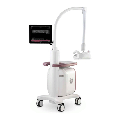
The LOGIQ™ 100 PRO is a compact portable ultrasound scanner which is designed for OB/GYN,
Abdomen, Urology and small part Scans using the convex, linear and micro-convex (Transvaginal)
probes. High quality images can be obtained by the proper selection of scan control parameters.
The diagnostic clarity is further enhanced by the different measurement and calculation packages
available in the system.
1-1-2 Purpose of Chapter 1
This chapter describes important issues related to safely servicing this ultrasound machine. The
service provider must read and understand all the information presented here before installing or
servicing a unit.
CONTENTS IN CHAPTER 1
1-1-3 Purpose of Service Manual
This Service Manual provides installation and service information for the LOGIQ™ 100 PRO
Ultrasound Scanning System and contains the following chapters:
1.) Chapter 1, Introduction: Contains a content summary and warnings.
2.) Chapter 2, Pre-Installation: Contains any pre-installation requirements for the
LOGIQ™ 100 PRO.
3.) Chapter 3, Installation: Contains installation procedure with installation checklist.
4.) Chapter 4, Functional Checks: Contains functional checks that must be performed as
part of the installation, or as required during servicing and periodic maintenance.
5.) Chapter 5, Theory: Contains block diagrams and functional explanations of the
electronics.
6.) Chapter 6, Service Adjustments: Contains instructions on how to make any available
adjustments to the LOGIQ™ 100 PRO.
7.) Chapter 7, Diagnostics/Troubleshooting: Provides procedures for running and
diagnostic or related routines for the LOGIQ™ 100 PRO.
8.) Chapter 8, Replacement Procedures: Provides disassembly procedures and
reassembly procedures for all changeable FRU.
Section Description Page Number
1-1 Overview 1-1
1-3 Important Conventions 1-4
1-4 Safety Considerations 1-9
1-5 EMC, EMI, and ESD 1-18
1-6 Customer Assistance 1-20
Table 1-1 Contents in Chapter 1
State:RELEASE-DocumentisreleasedandunderformalChangeControl.ChangesaresubjecttotheECR/ECOProcess.
SeetheGEHCMyworkshopSystemtodeterminethestatusofthisdocument.
ApprovedDocument-5305880-100TPH_r3.pdfPage18of197

GE HEALTHCARE
DIRECTION 5305880-100, REVISION 3 LOGIQ™ 100 PRO SERVICE MANUAL
Page 1-2 Section 1-1 - Overview
9.) Chapter 9, Replacement Parts: Contains a complete list of replacement parts for the
LOGIQ™ 100 PRO.
10.)Chapter 10, Quality Assurance: Provides periodic maintenance procedures for the
LOGIQ™ 100 PRO.
1-1-4 Typical Users of the Basic Service Manual
• Service Personnel (installation, maintenance, etc.).
• Hospital’s Service Personnel
• Architects (Some parts of the Pre Installation Chapter)
1-1-5 LOGIQ™ 100 PRO Models Covered by this Manual
1-1-6 Purpose of Operator Manual(s)
The Operator Manual(s) should be fully read and understood before operating the LOGIQ™ 100
PRO and also kept near the unit for quick reference.
Hcat Number Description Comments
H41072LA,H41072LB,
H41072LC,H41072LD,
H41072LE,H41072LF,
H41072LS
LOGIQ™ 100 PRO, 100V -
230V
Table 1-2 LOGIQ™ 100 PRO Models Covered in this Manual
State:RELEASE-DocumentisreleasedandunderformalChangeControl.ChangesaresubjecttotheECR/ECOProcess.
SeetheGEHCMyworkshopSystemtodeterminethestatusofthisdocument.
ApprovedDocument-5305880-100TPH_r3.pdfPage19of197

GE HEALTHCARE
DIRECTION 5305880-100, REVISION 3 LOGIQ™ 100 PRO SERVICE MANUAL
Chapter 1 - Introduction Page 1-3
Section 1-2 Safety
1-2-1 Warnings
WARNING CAREFULLY READ ALL THE WARNINGS BELOW
1.) The operator manual should be read and understood before operating the LOGIQ™ 100
PRO and kept nearby for quick reference.
2.) Although the ultrasound energy transmitted from the LOGIQ™ 100 PRO transducer is
within AIUM/NEMA standards, unnecessary exposure should be avoided. Only trained
personnel should operate the LOGIQ™ 100 PRO.
3.) To prevent electric shock, the LOGIQ™ 100 PRO should be connected to a properly
grounded power receptacle.Do not use a three prong to two prong adapter. This defeats
safety grounding/
4.) Probes are fragile, Please handle with care.
5.) Concerning outside markings, refer to Figure 1-2 through 1-3.
6.) For the cleaning, disinfection, and sterilization, refer to Probe section in LOGIQ™ 100
PRO User Manual and Caution Sheet supplied with each probe.
NOTICE This medical equipment is approved, in terms of the prevention of radio wave interference,
to be used in hospitals, clinics and other institutions which are environmentally qualified. The use
ofthis equipment is an inappropriateenvironmentmay cause some electronic interference to radios
and televisions around the eqiupment. Proper handling of this equipment is required in order to
avoid such trouble according to the operator and service manuals. This eqiupments can be used in
residential areas only under the supervision of physicians and qualified technicians.
CAUTION Improper performance possibility. Do not use the following devices near this
equipment. Cellular phone, radio transciever, mobile radio transmitter, radio-controlled toy,
etc. Use of thesedevices near this equipment could cause this equipment to perform outside
the published specifications. Keep power to these devices turned off when near this
equipment.
State:RELEASE-DocumentisreleasedandunderformalChangeControl.ChangesaresubjecttotheECR/ECOProcess.
SeetheGEHCMyworkshopSystemtodeterminethestatusofthisdocument.
ApprovedDocument-5305880-100TPH_r3.pdfPage20of197

GE HEALTHCARE
DIRECTION 5305880-100, REVISION 3 LOGIQ™ 100 PRO SERVICE MANUAL
Page 1-4 Section 1-1 - Overview
Section 1-3 Important Conventions
1-3-1 Conventions Used in Book
Model Designations.
This manual covers the LOGIQ™ 100 PRO scanners.
(See “LOGIQ™ 100 PRO Models Covered by this Manual” on page 1-2.)
Icons.
Pictures, or icons, are used wherever they will reinforce the printed message. The icons, labels and
conventions used on the product and in the service information are described in this chapter.
Safety Precaution Messages.
Various levels of safety precaution messages may be found on the equipment and in the service
information. The different levels of concern are identified by a flag word that precedes the
precautionary message. Known or potential hazards are labeled in one of three ways:
NOTE: Notes provide important information about an item or a procedure.
Information contained in a NOTE can often save you time or effort.
DANGER IS USED TO INDICATE THE PRESENCE OF A HAZARD THAT WILL
CAUSE SEVERE PERSONAL INJURY OR DEATH IF THE INSTRUCTIONS ARE
IGNORED.
WARNING IS USED TO INDICATE THE PRESENCE OF A HAZARD THAT CAN CAUSE
SEVERE PERSONAL INJURY OR PROPERTY DAMAGE IF INSTRUCTIONS ARE
IGNORED.
Caution is used to indicate the presence of a hazard that will or can cause minor personal injury
and property damage if instructions are ignored.
Equipment Damage Possible
Noticeisused whenahazardis presentthatcancausepropertydamagebuthasabsolutely nopersonal
injury risk.
DANGER
WARNING
CAUTION
NOTICE
State:RELEASE-DocumentisreleasedandunderformalChangeControl.ChangesaresubjecttotheECR/ECOProcess.
SeetheGEHCMyworkshopSystemtodeterminethestatusofthisdocument.
ApprovedDocument-5305880-100TPH_r3.pdfPage21of197
Table of contents
Other GE Medical Equipment manuals
Popular Medical Equipment manuals by other brands

Emfit
Emfit D-1090-2G user manual

Teleflex
Teleflex WECK EFx Shield quick start guide

Max-Ability
Max-Ability PRESSALIT R8961000 user guide

VitalGo
VitalGo Total-Lift Bed 425T Assembly, Operating and Maintenance Instruction

laerdal
laerdal 84501 Directions for use

On-X
On-X On-X Mitral Heart Valve with Standard Sewing... Instructions for use