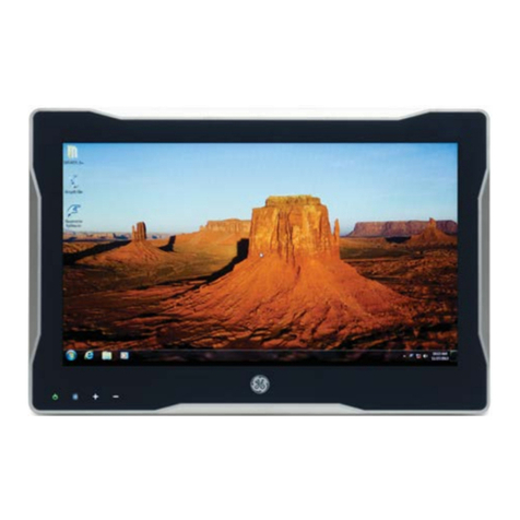
GE QuickPanel+ IC755CxS06RDx User manual

GFK-2847W
QuickPanel⁺Operator
Interface
User
Manual
Dec 2017
IC755CxS06RDx (6” Display)
IC755CxW07CDx (7” Display)
IC755CxS10CDx (10" Display)
IC755CxS12CDx (12” Display)
IC755CxS15CDx (15” Display)
For public
disclosure

For public disclosure
These instructions do not purport to cover all details or variations in equipment, nor to provide for every
possible
contingency
to be met during installation, operation, and maintenance. The information is supplied for informational
purposes only, and GE makes no warranty as to the accuracy of the information included herein. Changes, modifications,
and/or improvements to equipment and specifications are made periodically and these changes may or may not be
reflected herein. It is understood that GE may make changes, modifications, or improvements to the equipment referenced
herein or to the document itself at any time. This document is intended for trained personnel familiar with the GE products
referenced herein.
GE may have patents or pending patent applications covering subject matter in this document. The furnishing of
this document does not provide any license whatsoever to any of these patents.
Public –This document is approved for public disclosure.
GE provides the following document and the information included therein as is and without warranty of any
kind, expressed or implied, including but not limited to any implied statutory warranty of merchantability or
fitness for particular purpose.
For further assistance or technical information, contact the nearest GE Sales or Service Office, or an authorized GE Sales
Representative.
Revised: Dec 2017
Issued: Nov 2013
© 2013 - 2016 General Electric Company.
* Indicates a trademark of General Electric Company and/or its subsidiaries.
All other trademarks are the property of their respective owners.
We would appreciate your feedback about our documentation.
Please send comments or suggestions to controls.doc@ge.com

GFK-2847W 3
For public disclosure
Document Updates
Location
Description
Appendix A Product Certifications and Installation
Guidelines, Agency Approval
Updated ATEX Directive to 14/34/EU
Removed ATEX protection string - refer to the QP+ Operator Interface
Installation and Maintenance Requirements (IMR) (GFK-2981)
Conditions of Safe Use for Installation in Hazardous
Locations
Added the procedure for USB retaining clamps used in hazardous
location installations for 7” Display units
Acronyms and Abbreviations
ARM Advanced RISC Machine
BBSRAM Battery-backed SRAM
DRAM Dynamic Random Access Memory
FG Frame Ground
FTP File Transfer Protocol
GND Ground
GUI Graphical user interface HTTP
HyperText Transfer Protocol
LCD Liquid Crystal Display
LED Light-emitting Diode
MIB Management Information Base (or Database)
OS Operating System
PME Proficy Machine Edition
RoHS Restrictions on Hazardous Substances
SELV Safety Extra Low Voltage
SNMP Simple Network Management Protocol
USB Universal Serial Bus
VESA Video Electronics Standards Association

4 GFK-2847W
For public disclosure
QuickPanel⁺Operator Interface User
Manual
Safety Symbol Legend
Warning
Indicates a procedure or condition that, if not strictly observed, could result
in personal injury or death.
Caution
Indicates a procedure or condition that, if not strictly observed, could result in
damage to or destruction of equipment.
Attention
Indicates a procedure or condition that should be strictly followed to improve
these applications.

GFK-2847W 5
For public disclosure
Contact Information
If you purchased this product through an Authorized Channel Partner, then contact the seller directly.
General Contact
Information
Online technical support and GlobalCare
http://support.ge-ip.com
Additional information
http://www.ge-ip.com/
Solution Provider
solutionprovider.ip@ge.com
Technical Support
Contact us by telephone, email, or at http://support.ge-ip.com.
Americas
Online Technical Support
http://support.ge-ip.com
Phone
1-800-433-2682
International Americas Direct Dial
1-780-420-2010 (if toll free 800 option is unavailable)
Technical Support Email
Customer Care Email
customercar[email protected]
Primary language of support
English
Europe (not Germany), Middle East, and Africa (EMEA)
Online Technical Support
http://support.ge-ip.com
Phone
+ 800-1-433-2682
EMEA Direct Dial
+ 420-23-901-5850 (if toll free 800 option is unavailable or dialing from a
mobile telephone)
Technical Support Email
support.emea.[email protected]
Customer Care Email
customercar[email protected]m
Primary languages of support
English, French, Italian, Czech, Spanish
Germany
Online Technical Support
http://support.ge-ip.com
Address
GE Intelligent Platforms GmbH
Memminger Str. 14
86159 Augsburg
Germany
Phone
+ 49-821–5034–0
+ 800–322–3616
Fax
+ 49–821–5034–119
Technical Support Email
sales.augsbur[email protected]
Asia Pacific
(APO)
Online Technical Support
http://support.ge-ip.com
Phone
+ 86-400-820-8208
+ 86-21-3217-4826 (India, Indonesia, and Pakistan)
Technical Support Email
support.cn.ip@ge.com (China)
support.in.ip@ge.com (remaining Asia customers)
Customer Care Email
customercar[email protected]
customercare.cn.ip@ge.com
(China)

6 GFK-2847W
For public disclosure
QuickPanel⁺Operator Interface User
Manual
Notes

GFK-2847W 7
For public disclosure
Contents
1
Overview
.....................................................................................................................................
9
1.1 Specifications
............................................................................................................................................ 10
1.1.1 Physical Specifications and Mounting
Options............................................................................. 10
1.1.2 Environmental
Specifications ........................................................................................................ 15
2
Hardware..................................................................................................................................
17
2.1 Physical Characteristics
........................................................................................................................... 17
2.2 LED
Indicators............................................................................................................................................ 23
2.2.1 Operation Status
LEDs.................................................................................................................... 23
2.2.2 Ethernet Port Operation LEDs
....................................................................................................... 23
3
Software
....................................................................................................................................
25
3.1 Operating System
..................................................................................................................................... 25
3.2 Backup
Utility............................................................................................................................................. 25
3.3 Storage Manager
...................................................................................................................................... 25
3.4 Copy Project to SD
Card
............................................................................................................................ 26
3.5 Proficy Machine Edition Project
Update................................................................................................... 26
3.6 FTP
Server .................................................................................................................................................. 27
3.6.1 Remote User Authentication
......................................................................................................... 27
3.6.2 FTP with Removable Flash Devices
.............................................................................................. 27
3.7 HTTP Server
.............................................................................................................................................. 28
3.8 SNTP
Server............................................................................................................................................... 28
3.9 QuickPanel+ OS Utilities Settings Tool
..................................................................................................... 29
3.9.1 Firmware Upgrade
......................................................................................................................... 30
3.9.2 Firmware Upgrade for Specific Build
Version................................................................................ 32
3.9.3 Bypass Startup
Programs
............................................................................................................... 33
3.9.4 Reset Enhanced Security
................................................................................................................ 35
3.9.5 Enable or Disable
SNMP
Agent
....................................................................................................... 36
3.10 Display Screen Sensitivity
Tool ................................................................................................................ 38
3.11 Launch
Application
.................................................................................................................................. 39
3.12 VNC
Server
............................................................................................................................................... 40
3.13 Battery Life
Prediction............................................................................................................................. 41
3.14 Simple Network Management Protocol
(SNMP)
.................................................................................... 45
3.14.1 Configure Trap
Destinations........................................................................................................ 49
3.14.2 Enable or Disable
SNMP
Agent
.................................................................................................... 50
3.14.3 Export MIB to SD
Card.................................................................................................................. 50
3.14.4 Load MIB into SNMP
Manager .................................................................................................... 51
3.14.5 Data Types Mapping between PME Project and SNMP
............................................................. 52
3.14.6 Establish SNMP
Communication ................................................................................................. 52
3.15 Screensaver…………..
................................................................................................................................ 53
4 Pre-installation
Checks........................................................................................................
55
4.1 Unpacking and Inspection
................................................................................................................... 55
4.2 Basic Setup
............................................................................................................................................ 57
4.3 Initial
Startup
......................................................................................................................................... 58
4.3.1 Connecting Input
Power ..................................................................................................... 58
4.3.2 Initial
Configuration ............................................................................................................ 59
8 GFK-2847W
For public disclosure
QuickPanel⁺Operator Interface User
Manual
4.4 Runtime Setup
...................................................................................................................................... 59
4.5 Firmware
Updates................................................................................................................................. 60
4.6
Shutdown
.............................................................................................................................................. 60
5 Mounting and
Installation......................................................................................................
61
5.1 Protective Sheet
Installation
.................................................................................................................... 61
5.2 Mounting Location
................................................................................................................................... 62
5.3 Panel
Mounting
......................................................................................................................................... 63
5.4 Mounting and Installation Procedure
..................................................................................................... 66
5.5 VESA Arm
Mounting.................................................................................................................................. 68
5.6 Battery Installation and
Replacement
.................................................................................................... 69
5.6.1
IC755CxS06RDx
............................................................................................................................... 70
5.6.2
IC755CxW07CDx............................................................................................................................. 72
5.6.3
IC755CxSxxCDx
............................................................................................................................... 74
5.7
Connectors ............................................................................................................................................... 76
5.7.1 Power Connector Pin-out for IC755CxS06RDx, IC755CxW07CDx, and
IC755CxSxxCDx
........... 76
5.7.2 Ethernet for IC755CxS06RDx, IC755CxW07CDx, and IC755CxSxxCDx
...................................... 76
5.7.3 Serial Port Details
........................................................................................................................... 78
5.7.4 Universal Serial Bus (USB)
Ports
..................................................................................................... 84
5.7.5 Audio (LINE OUT) Details for IC755CxS06RDx, IC755CxW07CDx, and
IC755CxSxxCDx
............. 85
5.7.6 Audio (MIC IN) Details (Only Applicable to IC755CxS06RDx and
IC755CxW07CDx).................... 85
5.7.7 SD Card Slot and Storage
............................................................................................................... 86
6
Operation
......................................................................................................................................
89
6.1 Touchscreen Display
................................................................................................................................ 89
6.1.1 Display Brightness
Adjustment
............................................................................................... 89
6.1.2 Display Backlight
Configuration
.............................................................................................. 90
6.1.3 Touchscreen
Re-calibration
..................................................................................................... 91
6.2 Keyboard
Configuration............................................................................................................................ 92
6.2.1 External Keyboard
(Optional).................................................................................................... 92
6.2.2 Soft Input
Panel
......................................................................................................................... 92
6.3 Mouse
........................................................................................................................................................ 92
6.4
Printing....................................................................................................................................................... 93
6.5 Memory
..................................................................................................................................................... 94
6.5.1 DRAM Memory
..................................................................................................................... 94
6.5.2 Memory Allocation
Modification .............................................................................................. 95
7 Secomea Security
(Optional)....................................................................................................
97
7.1 Secomea Configuration
Tool
.................................................................................................................... 97
7.2 Secomea
Products
.................................................................................................................................... 98
8 Save and Restore Settings…………………………………………………………………………………………100
Appendix A Product Certifications and Installation
Guidelines.........................................
107
Appendix B Orderable Part
Numbers
Appendix C IC755CxS10CDx, IC755CxS12CDA,and IC755CxS15CDx Serial Port
Details

Overview
For public disclosure
GFK-2847W 9
1 Overview
Note This manual specifically describes the QuickPanel+ IC755CxS06RDx, IC755CxWxxCDx and IC755CxSxxCDx
display units.
The QuickPanel+ Operator Interface is an all-in-one micro-computer designed for maximum flexibility. The design is
based on an Advanced RISC Machine (ARM) core micro-processor to combine a high-resolution touchscreen operator
interface with a variety of communications options. Users can connect to most industrial equipment using the
QuickPanel+ communications ports.
The QuickPanel+ is equipped with several memory types to satisfy the most demanding applications. A section of
Dynamic Random Access Memory (DRAM) is split between the operating system, an object store, and application
memory. Additionally, a section of Non-volatile Random Access Flash Memory (NOVRAM), functioning as a virtual hard
drive, is divided between the operating system and persistent storage for application programs. Retentive memory is a
battery-backed Static Random Access Memory (SRAM) to store and protect data during a power failure.
QuickPanel+ Operator Interface
Display

10 GFK-2847W
For public disclosure
QuickPanel⁺Operator Interface User
Manual
1.1 Specifications
1.1.1 Physical Specifications and Mounting Options
1.1.1.1 IC755CxS06RDx Specifications
Item
Specification
Processor
Freescale i.MX535 (1 GHz ARM Cortex A8)
Memory
RAM
DDR3 SDRAM 512 MB
ROM
NAND FLASH 256 MB
SRAM
512 KB (with battery backup)
Operating System
Microsoft Windows Embedded Compact 7
Display
Type
5.7” TFT LCD
Resolution
320(W) x 240(H) pixels QVGA
Color
65,536
Brightness
375 cd/m2
Backlight
LED
Touchscreen
Touch Panel Type
Analog Resistive
Multi-touch
Single-touch
Communications
Ethernet Port
1x10Base-T / 100Base-TX
Serial Port
1x RS-232C (COM1) (5-pin connector)
USB, Host
2x USB 2.0 (Type-A) maximum power (5 Vat 0.5 A)
USB, Device
1x USB 2.0 (mini Type-B)
Storage
1x SD/SDHC card slot
Audio
1x Mic In (Mono) (3.5 mm jack),
1x Line Out (Stereo) (3.5 mm jack)
Noise Immunity
Noise Voltage
1500 V p-p
Pulse Duration
1µs
Rise Time
1ns
Input power
Rated Voltage
24 V dc ±20% (3-pin connector)
Power Consumption
15 W maximum
Frame Ground (FG)
Frame Ground (GND) is connected internally to Signal GND
Dimensions (L×W×D)
192 × 137 × 36 mm (7.56 × 5.39 × 1.42 in)
Weight
0.7 Kg (1.54 lb)
Mounting Options
Panel Cutout Dimensions
183.50 × 128.50 mm (7.22 × 5.06 in)
VESA Mount
75 x 75 mm (2.95 x 2.95 in)

Overview
For public disclosure
GFK-2847W 11
1.1.1.2 IC755CxW07CDx Specifications
Item
Specification
Processor
Freescale i.MX535 (1 GHz ARM Cortex A8)
Memory
RAM
DDR2 SDRAM 512 MB
ROM
SLC NAND 256 MB
SRAM
512 KB (with battery backup)
Operating System
Microsoft Windows Embedded Compact 7
Display
Type
7" Widescreen TFT LCD
Resolution
800(W) x 480(H) pixels WVGA
Color
65,536
Brightness
310 cd/m2
Backlight
LED
Touchscreen
Touch Panel Type
Projected capacitive
Multi-touch
Two-point
Communications
Ethernet Port
1x 10/100Base-T (RJ-45)
Serial Port
1x RS-232 UART port (5-pin connector)
USB, Host
2x USB 2.0 (Type-A) maximum power (5 Vat 0.5 A)
USB, Device
1x USB 2.0 (mini Type-B)
Storage
1x SD/SDHC card slot
Audio
1x Mic In (Mono) (3.5 mm jack)
1x Line Out (Stereo) (3.5 mm jack)
Noise Immunity
Noise voltage
1500 V p-p
Pulse duration
1µs
Rise time
1ns
Input power
Rated Voltage
24 V dc ±20% (3-pin connector)
Power Consumption
15 W maximum, 0.625 A
Frame Ground (FG)
Frame GND is connected internally to Signal GND
Dimensions (L×W×D)
192 × 137 × 36 mm (7.56 × 5.39 × 1.42 in)
Weight
0.80 kg (1.76 lbs)
Mounting Options
Panel Cutout Dimensions
183.50 × 128.50 mm (7.22 × 5.06 in)
VESA Mount
75 x 75 mm (2.95 x 2.95 in)

12 GFK-2847W
For public disclosure
QuickPanel⁺Operator Interface User
Manual
1.1.1.3 IC755CxS10CDx Specifications
Item
Specification
Processor
Freescale i.MX535 (1 GHz ARM Cortex A8)
Memory
RAM
DDR3 SDRAM 1 GB
ROM
SLC NAND 512 MB
SRAM
512 KB (with battery backup)
Operating System
Microsoft Windows Embedded Compact 7
Display
Type
10.5" Standard TFT LCD
Resolution
800(W) x 600(H) pixels SVGA
Color
65,536
Brightness
400 cd/m2
Backlight
LED
Touchscreen
Touch Panel Type
Projected capacitive
Multi-touch
Two-point
Communications
Ethernet Port
2x 10/100Base-T (RJ-45)
Serial Port
1x RS-232 UART port
1x RS-232/485 port (2x 5-pin connector)
USB, Host
2x USB 2.0 (Type-A) maximum power (5 Vat 0.5 A)
USB, Device
1x USB 2.0 (mini Type-B)
Storage
1x SD/SDHC card slot
Audio
1x Line Out (Stereo) (3.5 mm jack)
Noise Immunity
Noise voltage
1500 V p-p
Pulse duration
1µs
Rise time
1ns
Input power
Rated Voltage
12/24 V dc ±20% (3-pin connector)
Power Consumption
18 W maximum 1.5 / 0.75 A
Frame Ground (FG)
Frame GND is connected internally to Signal GND
Dimensions (L×W×D)
278 × 222 × 65 mm (10.95 × 8.74 × 2.56 in)
Weight
2.40 kg (5.29 lbs)
Mounting Options
Panel Cutout Dimensions
266 × 210 mm (10.47 × 8.27 in)
VESA Mount
100 x 100 mm (3.94 x 3.94 in)

Overview
For public disclosure
GFK-2847W 13
1.1.1.4 IC755CxS12CDx Specifications
Item
Specification
Processor
Freescale i.MX535 (1 GHz ARM Cortex A8)
Memory
RAM
DDR3 SDRAM 1 GB
ROM
SLC NAND 512 MB
SRAM
512 KB (with battery backup)
Operating System
Microsoft Windows Embedded Compact 7
Display
Type
12.1" Standard TFT LCD
Resolution
800(W) x 600(H) pixels SVGA
Color
65,536
Brightness
450 cd/m2
Backlight
LED
Touchscreen
Touch Panel Type
Projected capacitive
Multi-touch
Two-point
Communications
Ethernet Port
2x 10/100Base-T (RJ-45)
1x 10/100Base-T (RJ-45) for IC755CxS12CDA
Serial Port
1x RS-232 UART port
1x RS-232/485 port (2x 5-pin connector) (1x
10-pin connector for IC755CxS12CDA)
USB, Host
2x USB 2.0 (Type-A) max power (5
V
at 0.5 A)
USB, Device
1x USB 2.0 (mini Type-B)
Storage
1x SD/SDHC card slot
Audio
1x Line Out (Stereo) (3.5 mm jack)
Noise Immunity
Noise voltage
1500 V p-p
Pulse duration
1µs
Rise time
1ns
Input power
Rated Voltage
12/24 V dc ±20% (3-pin connector)
Power Consumption
30 W maximum, 2.5 / 1.25 A
Frame Ground (FG)
Frame GND is connected internally to Signal GND
Dimensions (L×W×D)
314 × 248 × 65 mm (12.36 × 9.76 × 2.56 in)
Weight
3 kg (6.61 lbs)
Mounting Options
Panel Cutout Dimensions
302 × 228 mm (11.89 × 8.98 in)
VESA Mount
100 x 100 mm (3.94 x 3.94 in)

14 GFK-2847W
For public disclosure
QuickPanel⁺Operator Interface User
Manual
1.1.1.5 IC755CxS15CDx Specifications
Item
Specification
Processor
Freescale i.MX535 (1 GHz ARM Cortex A8)
Memory
RAM
DDR3 SDRAM 1 GB
ROM
SLC NAND 512 MB
SRAM
512 KB (with battery backup)
Operating System
Microsoft Windows Embedded Compact 7
Display
Type
15" Standard TFT LCD
Resolution
1024(W) x 768(H) pixels XGA
Color
65,536
Brightness
310 cd/m2
Backlight
LED
Touchscreen
Touch Panel Type
Projected capacitive
Multi-touch
Two-point
Communications
Ethernet Port
2x 10/100Base-T (RJ-45)
Serial Port
1x RS-232 UART port
1x RS-232/485 port (2x 5-pin connector)
USB, Host
2x USB 2.0 (Type-A) maximum power (5 Vat 0.5 A)
USB, Device
1x USB 2.0 (mini Type-B)
Storage
1x SD/SDHC card slot
Audio
1x Line Out (Stereo) (3.5 mm jack)
Noise Immunity
Noise voltage
1500 V p-p
Pulse duration
1µs
Rise time
1ns
Input power
Rated Voltage
12/24 V dc ±20% (3-pin connector)
Power Consumption
30 W maximum, 2.5 / 1.25 A
Frame Ground (FG)
Frame GND is connected internally to Signal GND
Dimensions (L×W×D)
399 × 323 × 70 mm (15.71 × 12.72 × 2.76 in)
Weight
4.46 kg (9.83 lbs)
Mounting Options
Panel Cutout Dimensions
379 × 305 mm (14.92 × 12.01 in)
VESA Mount
100 x 100 mm (3.94 x 3.94 in)

Overview
For public disclosure
GFK-2847W 15
1.1.2 Environmental Specifications
Note Install the QuickPanel+ in a well-ventilated location that is not exposed to dust, corrosive gases or liquids, rain,
strong ultra-violet light or direct sunlight, and meets the following specifications.
Item
IC755CxS06RDx
IC755CxW07CDx
IC755CxS10CDx
IC755CxS12CDx
IC755CxS15CDx
Cooling
Natural
convection
Ambient
Operating
Temperature
0 to 55°C (32 to 131
°F)
Ambient
Storage
Temperature
-10 to 60°C (14 to 140
°F)
Ambient
Humidity
(Operating
and Storage)
85% RH Non-condensing, wet-bulb temperature: 30°C (86 °F) or less
Environment
Pollution Degree 2, Indoor use
only
Vibration
Resistance
5 to 9 Hz single-amplitude 3.5 mm; 9 to 150 Hz
constant-accelerated
velocity 9.8 m/s2; X, Y,
Z directions 10 time (100 minutes) (Compliance 3502, IEC61131-2 JIS B)
Altitude
800~1114 hPa, altitude up to 2000 m (6561.68 ft)
RoHS
Compliant with EU RoHS Directive 2011/65/EU
Enclosure
Rating
UL
Type 4X rating; IP65 in panel mount only
Note For additional product standards and agency approvals, refer to Appendix A.

16 GFK-2847W
For public disclosure
QuickPanel⁺Operator Interface User
Manual
Notes

Hardware
For public disclosure
GFK-2847W 17
2 Hardware
This chapter describes the QuickPanel+ hardware features, including physical characteristics and LED
indicators.
2.1 Physical Characteristics
In addition to the primary touchscreen interface, the QuickPanel+ Operator Interface supports a variety of
communication ports. The following diagrams illustrate the physical layout of the QuickPanel+ Operator Interface,
including locations of status LEDs, communications ports, and connectors.

18 GFK-2847W
For public disclosure
QuickPanel⁺Operator Interface User
Manual
144.7 (5.70 in)
128.50 (5.06 in)
75 (2.95 in)
137 (5.39 in) x 2
192 (7.56 in) x 2 36 (1.42 in) x 2
115.2
(4.5 in)
SD Card
LCD Active Area
115.2 x 86.4
(4.5 x 3.4 in)
Serial Interface
Input Power LAN USB Host Ports
USB Device
LINE OUT
MIC IN
183.50 (7.22 in)
75 (2.95 in)
Battery Cover
Effective Screw Depth 6 mm (0.24 in) License Label
Product Nameplate
IC755CxS06RDx Hardware
Features

Hardware
For public disclosure
GFK-2847W 19
Touchscreen
LCD
S
t
a
t
us
Indicator LED
SD Card
MICRO USB
LINE OUT
MIC
I
N
I
npu
t
Power
LAN
USB Hos
t
Por
t
s
COM
Ba
tt
ery
Cover
IC755CxW07CDx Hardware
Features
Note Refer to the section IC755CxW07CDx Specifications for drawing dimensions.

20 GFK-2847W
For public disclosure
QuickPanel⁺Operator Interface User
Manual
SD Card
St
a
t
us
Indicator L
E
D
T
ouchscreen
LCD
L
A
N2 L
A
N1 U
SB
Hos
t
P
or
t
s
MICRO C
O
M2
U
SB
C
O
M1 L
I
N
E
O
U
T
I
npu
t
P
ower
IC755CxS10CDx Hardware
Features
Note Refer to the section IC755CxS10CDx Specifications for drawing dimensions.
Other manuals for QuickPanel+ IC755CxS06RDx
2
This manual suits for next models
4
Table of contents
Other GE Monitor manuals

GE
GE Kelman Minitrans User manual

GE
GE 3500/40M User manual

GE
GE TRANSFIX DGA 500 User manual

GE
GE CareScape V100 User manual

GE
GE Dash 3000 User manual

GE
GE Dash 3000 User manual

GE
GE CARESCAPE User manual

GE
GE PACSystems ICRXIDIXNE19LCTA User manual

GE
GE Bently Nevada 1900/27 User manual

GE
GE IC754VKI06MTD User manual