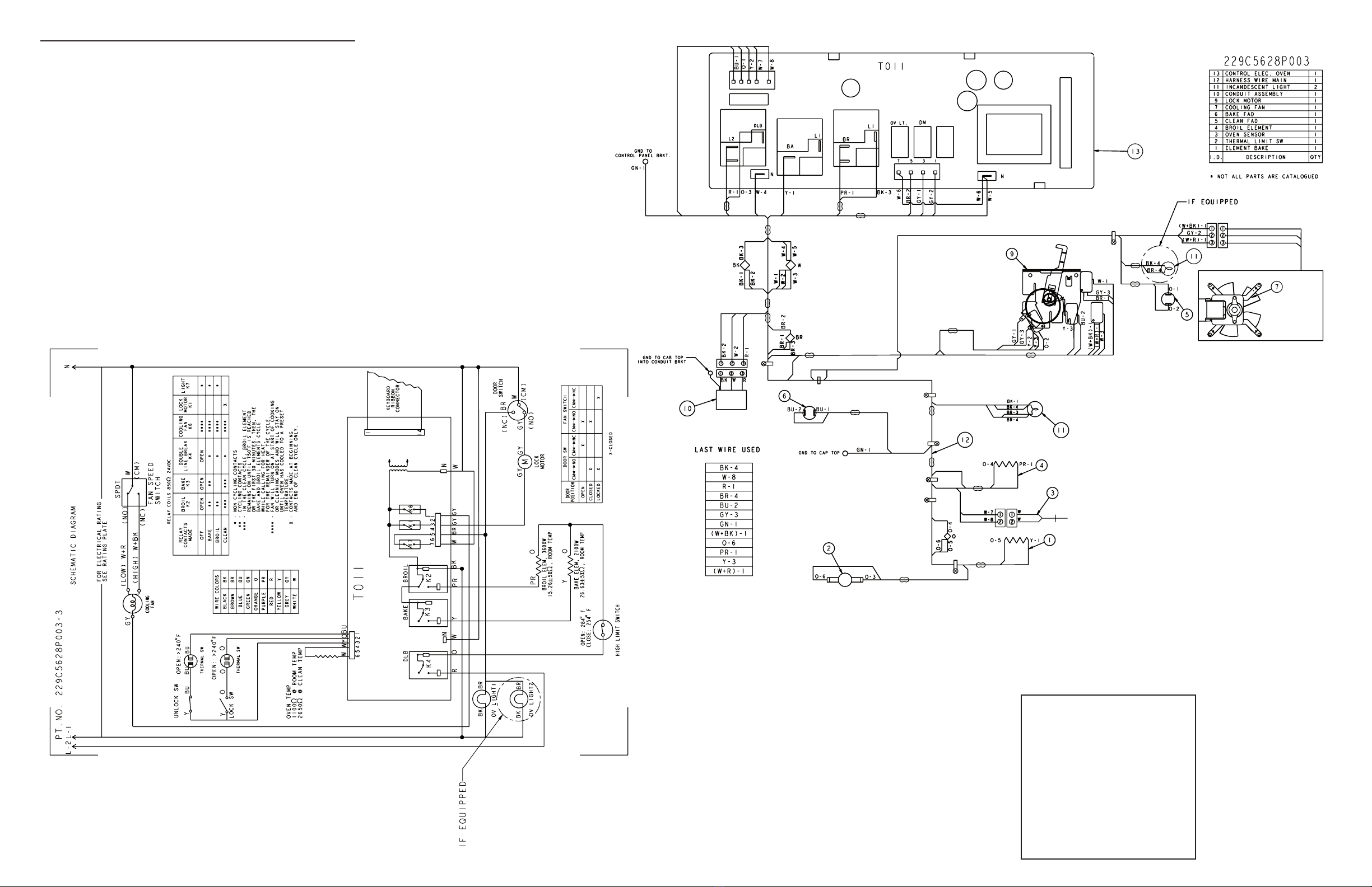
30” ELECTRIC WALL OVEN W/ ERC III
CONTROL AND MOTORIZED DOOR LOCK
IMPORTANT SAFETY NOTICE: This information is intended for use by individu
als pos sess ing adequate backgrounds of electrical, elec tron ic and mechanical
experience. Any at tempt to repair a major ap pli ance may result in personal
injury and property damage. Neither the manufacturer nor the seller can be
responsible for the in ter pre ta tion of this information or assume any liability in
connection with its use.
DISCONNECT POWER BEFORE SERVICING
IMPORTANT: RECONNECT ALL GROUNDING DEVICES. All parts of this appliance capa
ble of con duct ing electrical current are grounded. If ground ing wires, screws, straps,
clips, nuts or washers used to com plete a path to ground are removed for service,
they must be returned to their original position and properly fastened.
GROUNDING SPECIFICATIONS
Ground Path Resistance 0.10Ω Max.
Insulation Resistance 250KΩ Min.
ALUMINUM WIRE: CAUTION – This oven power supply cable is rec
og nized for copper wire only, NOT ALUMINUM WIRE. Refer to In stal la tion Instructions for
additional details.
ELEC TRON IC CON TROL
CAUTION:
Com po nents are elec tri cal ly HOT
on con trol when voltage is con
nect ed to oven.
The Electronic Oven Control system consists of the control, key panel, oven sensor,
door and lock assembly.
NOTE: Tem per a ture/Mode
Selection is necessary for
op era tion of Relay contacts.
NOTE: Voltage must be pres
ent across terminals L1 to N
for control to operate.
OVEN SENSOR AND DOOR SWITCH OHMMETER TEST
(See “Motorized Door Lock Operation” for door switch function ex pla na tion.)
Remove power from oven. Make resistance meas ure ment from side of sensor and lock
switch connector, with exposed terminals disconnected from the control.
* If abnormal reading is
observed, remove sensor
from oven and check at dis
connect block. Wiggle leads
while checking
re sis tance. If more than 10Ω
variation, replace.
OVEN CALIBRATION
Testing has shown that this oven has the best cooking performance at a control set
ting of 350°F when the AVERAGE center oven temperature is between 335°F and
395°F. Customers may change the average center oven temperature by +/35°F to
satisfy their own cooking needs. This affects only BAKE. SELFCLEAN and BROIL are
not affected.
To change:
• Press and hold BAKE and BROIL pads until “SF” appears in the display.
• Press BAKE pad to enter oven calibration mode. “00” or a number between + and
35°F will be displayed.
• Press TEMP increase or decrease pads to change average oven temperature.
• Press START to return to Time of Day.
SPECIAL FUNCTIONS (cont.)
• EndofCycle Tone – Press TIMER pad. Display shows “Con Beep” when control
is set for continuous EndofCycle Tone or “Beep” when set for noncontinuous.
• °F and °C – Press the BROIL and COOK TIME pads at the same time. Display will
show either “°F” or “°C”. Press the BROIL and COOK TIME pads again to change.
• 12hour, 24hour, or blank out Time of Day Clock – Press CLOCK pad. Display will
show “12 hr,” “24 hr,” “OFF” for blank clock. Press again to change.
• COOK AND HOLD (used only with Time Bake or Delay Bake functions) –
Press COOK TIME pad. Display will show either “HLD On” or “Hld Off.” Press again to
change.
• 12Hour Shutdown comes set to shut down after 12 hours of con tin u ous operations;
this can be eliminated—press DELAY START pad. Display will show “No Shdn.” To turn
back on, press DELAY START pad again and display will show “12 Shdn.”
• Sabbath Mode (GE models only) – This feature disables all but Bake and Timed Bake,
overrides 12Hour Shutdown, disables beeps, and puts symbols in the display during
Bake. Press the DELAY START pad to activate. Display will show “SabbAtH.” To
deactivate, press the DELAY START pad. Display will show “no Shdn” or “12 Shdn.”
The control has other features which are also activated by specific key press
combinations:
• Sales Mode (special feature for sales floor demonstration) – Press the CLOCK and
TIMER pads at the same time. Display will start to cycle through the
different modes of operation.
• Control Lockout – Press the HR DOWN and MIN DOWN slew keys for 3 (three)
seconds. Display will show “Loc On.” To unlock the oven, press the HR DOWN and
MIN DOWN slew keys for 3 (three) seconds. Display will show “Loc Off.” No keys
are active while the control is locked, and the display will show “Loc On” if a pad is
pressed while the control is locked.
CONTROL VOLTAGE
TERMINALS
L1 TO N
VOLTAGE
120 VAC ALL THE TIME
120 VOLTS when oven is not call
ing for heat (BAKE and BROIL relay
contacts closed).
DLB TO BAKE
DLB TO BROIL
120 VAC when light is off.
120 VAC locking or unlocking.
AUX1N
*L1 to J4 7
OVEN CIRCUITS
SENSOR AND LOCK
SWITCH CONNECTOR
* BAKE AND BROIL UNITS CAN BE ON AT THE SAME TIME.
• BAKE/TIME BAKE – Bake and broil units operate
simultaneously during Preheat. Broil unit is on
approximately 25% of the time during the balance of the
Bake operation, with approximately one minute of dead
time between units.
• CLEAN – Broil unit only on during first 30 minutes or until
oven reaches 750°F. During the balance of the Clean
operation, the oven will use the bake and broil units
simultaneously and separately, with one second of dead
time between units while calling for heat.
ERC FAILURE CODES
Only an F9 code will be displayed to the customer although all codes will be stored in
memory. The oven may stop operating but not give an F code on the
display immediately. F codes are stored in nonvolatile EEPROM memory until
the same fault occurs twice consecutively. After that, the F code will be displayed. F
codes can be recalled by pressing together TIMER, CLOCK and MIN DOWN. While F
codes are displayed, pressing MIN UP and HR DOWN together will clear them. A fault
must exist continuously for several minutes before an F code is stored (F2 and F8 are
1 minute or less).
THERMAL CUTOUT SWITCH
A selfresetting, disctype thermal cutout switch is mounted
to the rear of the oven. The switch will open the L2 leg of
the power to the heating elements in the event of an over
temperature condition. The switch will open when the panel it is
mounted to reaches approximately 284°F and will close as the
panel cools to approximately 254°F. There is no indication to
the customer when the switch opens or closes.
FAILURE
CODE
Determine if problem is with Key Panel or Control by dis
con nect ing ribbon cable and measuring flat cable pins 3
to 4. Should be to probe side with conductor. Should be
125–175 ohms while pressing OFF key.
F2 • Welded relay contacts
• Airflow to rear of unit
• High resistance in oven sensor leads/con
nec tors (es pe cial ly at sensor
in rear)
Shorted OFF key
F0
Oven temperature
inside oven cavity as
mea sured by sensor
over 650°F un latched or
915°F latched
F3 Open oven sensor
(over 3000 ohms)
Shorted oven sensor
(under 950 ohms)
F4 • Disconnect power. Disconnect sensor harness from
con trol. Measure sen sor resistance (white leads) to be
~1080 ohms at room tem per a ture
with 2 ohms per degree change.
• Separate sensor from harness to determine fault.
Shorted matrix or
START key
F7 Determine if problem is with Key Panel or Control by
dis con nect ing flat cable and measuring cable pins using
pinout chart. Allow up to 1000 ohms when pressing a
key.
F8 EEPROM data shift
failure
If repeated, replace control.
F9 Cooling fan stalls or other
cause of open thermal
switches in yellow, blue or
orange leads.
Suspect cooling fan (between ov ens) or airflow.
COR REC TION
MEANING
Sensor circuit supervi
sor failure
F5 Replace control.
• Disconnect power. Disconnect sensor harness from
con trol. Measure sen sor resistance (white leads) to be
~1080 ohms at room temperature
with 2 ohms per degree change.
• Look for damaged harness terminals if not a bad
sensor.
CIRCUIT TERMINALS OHMS
Oven Sensor J1 4 to 6 1080Ω @ Rm Temp.*
2562Ω @ 825°F
Door Unlatched J1 1 to 3 0Ω
J1 2 to 3 open
Door Latched J1 2 to 3 0Ω
J1 1 to 3 open
*If oven light is not working, make the following checks:
• Check oven light bulb to verify it works.
• Light comes on when door is opened. Check for 120VAC from J4 7 and J4 5 termi
nals to L1. If 120VAC is not present, press the oven door switch in and out several
times, leaving the oven door open. Recheck for 120VAC from J4 7 and J4 5 termi
nals to L1 with the oven door open. If 120VAC is not present, replace the oven door
switch.
• Close oven door. Check for 120VAC from J4 7 and J4 5 terminals to L1. If 120VAC is
present but the light does not turn on, the light bulb is bad or there is a loose con
nection in the wires harness. If 0 VAC, press Oven Light key on key panel and retry. If
still 0 VAC, check the key panel. If key panel is OK, replace the control. (If you hear a
relay click when the Oven Light key on the control panel is pressed, the key panel is
working.)
1
2
3
4
6
SENSOR CONNECTOR
SENSOR
1080W @
ROOM
TEMP.
HIGH TEMP
THERMAL SWITCH
LOCK SW. 1
LOCK SW. 2
OVEN SENSOR
CIRCUIT
PINS 4 & 6
DOOR LATCH OUTPUT
-25 VDC AT ALL TIMES
MEASURED TO GROUND
DOOR LATCH INPUT
DOOR UNLATCHED INPUT
LOW TEMP
THERMAL SWITCH
MOTORIZED DOOR LOCK
The motorized door lock assembly is located above the oven. The assembly consists of
a lock motor cam and switch assembly, lock hook, mounting plate, door switch, spring
and plunger.
Motorized Door Lock Operation:
The lock motor is en er gized when the control is set for
Clean and Clean Time is selected. The K7 (upper) or K8
(lower) relay contact will close and complete the circuit
that supplies the voltage to the lock motor.
NOTE: To enable proper operation of the door lock, ensure that
the door jamb switch is in “common” to “normally OPEN” (door
closed) position. This enables power to be delivered when the
door lock closes.
NOTE: Display of Control will flash “LOCK” if the door switch
is in the “C” (common) to “NC” (normally CLOSED) (door open)
position.
• The words “LOCK DOOR” will flash on and off in the display
while the lock mo tor is in motion. When the door is locked the words “LOCKED
DOOR” remain il lu mi nat ed in the display.
• CAM – The cam on the motor per forms two functions:
1. Positions the lock hook in the door to prevent opening during Clean op er a tion.
2. Operates the lock switches which tell the control if the door is unlocked or locked
and ready for Clean operation.
NOTE: When door is either being locked or unlocked, both the lock and unlock
switches will be in the open position.
LOW TEMP
THERMAL SW
HIGH TEMP
THERMAL SW
O
Y
Y
YBUBU
1
2
3
4
5
6
LOCK SW
UNLOCK SW
THERMAL SW
HIGH TEMP
THERMAL SW
O
Y
Y
YBUBU
1
2
3
4
5
6
LOCK SW
UNLOCK SW
HIDDEN BAKE
To Service:
Access from rear and side.
1. Remove power.
2. Remove lower wire cover.
3. Unplug element.
4. Remove screws holding element in
hidden bake assembly.
5. Remove left side insulation retainer.
6. Remove side of hidden bake assembly.
7. Remove element.
3. Fully open the door. If the door will not fully open,
the indentation is not seated correctly in the bottom
edge of the slot.
4. Push the hinge locks up against the front frame of
the oven cav i ty, to the locked po si tion.
5. Close the oven door.
REMOVABLE OVEN DOOR
The door is very heavy. Be careful when removing
and lifting the door.
Do not lift the door by the handle.
To Remove:
1. Fully open the door.
2. Push the hinge locks down toward the door frame,
to the un locked po si tion. A tool, such as a small flatblade
screw driv er, may be required.
3. Firmly grasp both sides of the door at the top.
4. Close door to the door re mov al position.
5. Lift door up until the hinge arm is clear
of the slot.
To Replace:
1. Firmly grasp both sides of the door at the top.
2. With the door at the same an gle as the
re mov al po si tion, seat the in den ta tion of the
hinge arm into the bot tom edge of the hinge
slot. The notch in the hinge arm must be fully
seated into the bottom of the slot.
Removal position
Bottom
Edge of Slot Hinge
Arm
Indentation
Hinge Arm
Hinge
Lock
Push hinge locks up to lock
SPECIAL FUNCTIONS
The control has a section that can be entered to change how the control will work. To
enter this section, press and hold the BAKE and BROIL pads for 3 (three) seconds and
“SF” appears in the display. Select the area to change. When the change has been
made, press START to return to the Time of Day.
Slot
Hinge Lock
Pull hinge locks
down to unlock
3114960
Two configurations exist for the motorized door lock circuit. The alternate
configuration is shown below (applies to sensor and lock switch connector
diagrams as well.)
LOW TEMP
THERMAL SW
HIGH TEMP
THERMAL SW O
Y
Y
YBUBU
LOCKED
1
2
3
4
5
6
LOCK SW
UNLOCK SW
O
LOW TEMP
THERMAL SW
HIGH TEMP
THERMAL SW O
Y
Y
YBUBU
UNLOCKED
1
2
3
4
5
6
LOCK SW
UNLOCK SW
O
THERMAL SWITCHES
The lower temperature thermal switch, normally closed, is located behind the cool
ing fan and wired in series with the unlock switch on the lock motor thus only active
during nonselfclean operations. The higher temperature thermal switch, normally
closed, is located in the component compartment in front of the cooling fan and wired
in series with the lock switch on the lock motor thus only active during selfclean
operations.
If the thermal switch opens in any mode of operation, the control will go to –F9 fail
ure code. When this condition exists, check the fan operation (look for obstructions),
inspect oven installation (make sure duct areas are not blocked), oven insulation, and
lock circuit
*See label wire diagram for thermal switch setpoints