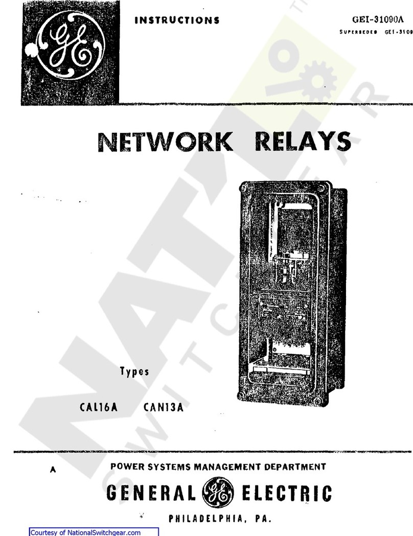
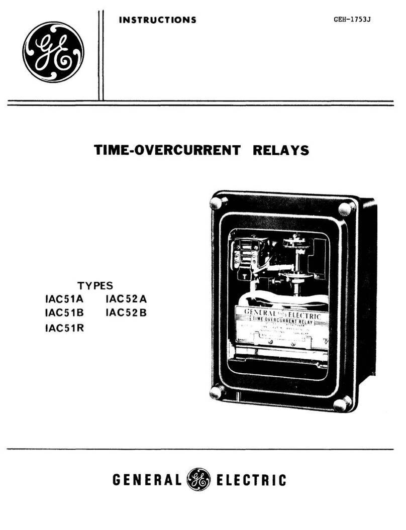
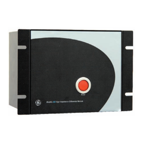
GE CAL16A User manual

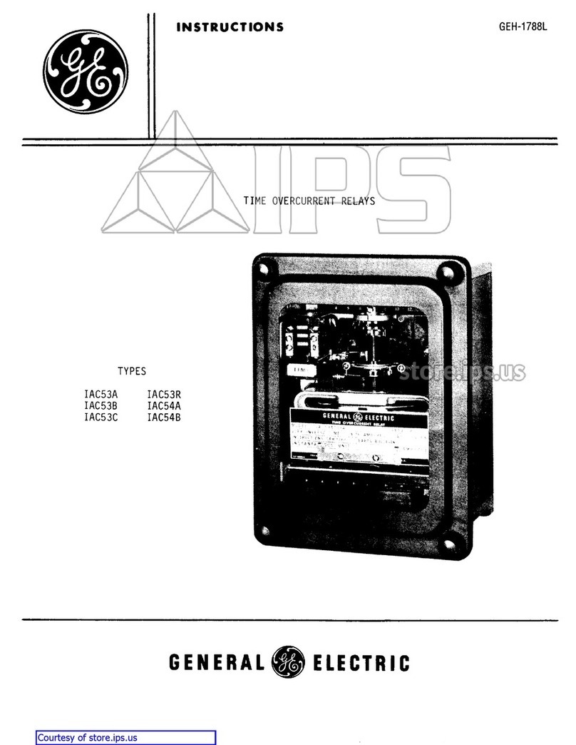
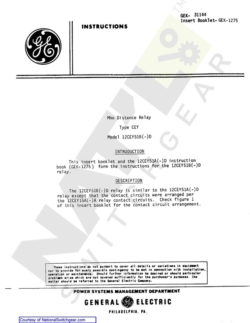
INSTRUCTIONS
GEI-31090A
Su.,
......
GEI.Slog(
NETWORK
RELAYS
Types
CAL16A
CAN13A
_____
'_._.
___
~"_.
____________
..
_:,.
...
~4»...
...:a:::
....
A POWER SYSTEMS
MANAGEMENT
DEPARTMENT
GENERALe
£LECTqle
PHILADELPHIA,
PA.


L
..
>
.3
NETWORK
RELAY
TYPES
CAL16A
AND
CAN13A
INTRODUCTION
With a few
el;',
eptions, the Type CAL16A and
CAN13A
relays
are
Identical
In
conslruction and
function to the
standard
secondary
network
relays
shown
In
the Included
Instruction
book GEI-13580.
The
CAN13A wlll
prevent
reclosure
if
the
source
phase
sequence
Is
reversed
and
the network
phase
sequence
Is
normal.
The
principal
difference
af-
fecting
both
relays
Is
that
Ihe
glass
cover
and
mountlng
bracket
have been
removed,
and the
relays
have been mounted
In
the
drawout
case
for mounllng
on a panel. Also, both
relays
have 2
ampere
holding
coils
In
the
reclose
circuits,
Instead
of
the 0.3
ampere
coils
as
In
the
standard
relay.
The
Type CAN13A
relay
differs
from the Type
CANllA
relay
In
several
points
concerning physical
construction
and
electrical
connections. The only
change
in function
is
that
It
Is designed to
trip
at
approximately
0.005
ampere,
current
transformer
secondary
current,
In
phase
with
line-to-neutral
voltage. It
is
intended to be
used
for tripping when
the only
reverse
power flowing Is the magnetizing
current
of the
associated
power
Iransformer.
The
principal
diHerences
between the Type
CAN13A
relay
and the Type CANIlA relay
are
as
follows:
1. The
reclose
contact
Is on the left and the Irlp
contact
on the
right,
facing the
relay,
On
the
Type
CAN
13A
relay.
This Is the
reverse
of the
Type
CANllA
relay.
2.
The
rna
In
control
spring
Is
used
to
adjust
trip
value
and
the mechanical
restraint
Is
used
to
adjust
r~close
value on the Type CAN13A
relay.
3.
The
electrical
restraint
element
has
been
omitted
on the
Type
CANI1A
relay.
4.
The
potential
coils,
Instead of
being
connected
directly
to the network
side
of the
breaker
are,
connected
to a
reststor
combination
across
each
pole
of the
associated
breaker.
This
last
feature
allows the
potential
coils
to
be
energized
from
the network
side
when the
source
side
Is
de-energized;
or
from the
source
side
when
the network
side
is
de-energized.
When the
breaker
is
closed,
the two
sections
of the
resistor
com-
bination on each
phase
are
effectively
In
parallel
and the net
resistance
is
the
same
as
that
ordinarily
used with the Type CANIIA
relay
(I.e.,
340 ohms
when 6054912
GS
Is
used
as
the
phase-shiftlng
trans-
for
mer,
and
when the 900 ohm
resistor
Is
used
in
the
phase
circuit
for 1.5 volt
reclosure.)
Therefore
the
tripping
characteristic
is
the
same
except
that
the
setting
is
0.1%
insteadofO.2%ofthe
relay
rating.
RECEIVING,
HANDLING
AND
STORAGE
The
relays,
when not Included
as
a
part
of
a
control
panel,
will be shipped in
cartons
designed
to
protect
them
against
damage.
Immediately
upon
receipt
of a
relay
examine
It
for any damages
sus-
taIned in
transit.
11
injury
or
damage from rough
handling
is
evident, file a
damage
claim
at
once
with the
transportation
company and promptly notify
the
nearest
General
Electric
Apparatus
Sales OHice.
Reasonable
care
should be
exercised
in
unpack-
Ing
the
relay
in
order
thai none of the
parts
are
Injured
or
the
adjustments
dlstrubed.
If
the
relays
are
not to be Installed
immediately,
they should
be
stored
in
their
original
cartons
in
a
place
that
Is
free
from
moisture,
dust
and
metallic
chips.
Foreign
matter
collected
on
the
outside
of
the
case
may lind
its
way Inside when the
cover
is
removed and
cause
trouble
in
the
operation
of the
relay.
DESCRIPTION
RELAY
CASE
The
case
is
suitable
for
either
surface
or
semi-flush
panel
mounting
and
an
assortment
of
hardware
is
provided
for
either
mounting. The
cover
attaches
to the
case
and
also
carries
the
reset
mechanism
when one
is
required.
Each
cover
screw
has
provision
for a sealing
wire.
The
case
both ends
or
connections.
has
studs
or
screw
connectlons
at
at
the bottom only
for
the
external
The
electrical
connectlons between
Th<ese
instructions
do
not
purport
to
cover
all
details
or
variations
in
eqUipment
llor
to
provide
for
every
possible
ccntingency
to
be
met
in
connection
with
installation,
operation
or
maintenance.
Should
further
infonrldtion
be
desired
or
should
p,uticuldr
problems
arise
",hich
.Ice
not
covered
sufficiently
foc
the
purchaser's
purposes,
the
mdttec
should
be
referred
to
the
General
~lectrjc
Company.
To
the
extent
required
the
prcxlucts
described
herein
meet
applicdble
ANSI,
IEEE
and
NEliA
stdnddIdsl
but
no
such
assurance
is
given
with
respect
to
local
codes
4nd
ordinances
because
they
vary
greatly.
3

GEl-31000 Network Relays Types CALl6A and CANUA
the
relay
untlll and the
case
studs
are
made through
sprtng
backed contact
fingers
mounted
In
stationary
molded Inner and outer blocks between which neslll
a
removable
connecting plug which completes the
circuits.
The outer blocks, attached to
th~
case,
have the
studs
for the
external
connecttons, and the
Inner blocks have the
terminals
for the Internal
connections.
The
relay
mechanism Is mounted
In
a
steel
framework
called
the
cradle
and Is a complete unit
with
all
leads
being
terminated
at
the Inner block.
This
cradle
Is held
firmly
In
the
case
with a latch
at
the top and the bottom and
by
a guide pin at the
back of the
case.
The
cases
and
cradles
are
so
constructed
that the
relay
cannot be Inserted
In
the
case
upside down. The connecting plug,
besides
making the
electrical
connections between the
re-
epecllve blocks
of
the
cradle
and
case,
also
locka the
latch
In
place. The coverl which Is
lstened
to the
caRe
by
thumbscrews,
hol<1ll
the connecting plug In
place.
To
draw out the relay unit the
cover
Is
lIrst
removed, and the plug drawn out. Shorting
bars
are
provided
In
the
case
to
short
the our
rent
transfor-
mer
circuits.
The latches
are
then
released,
and
the relay unit can
be
easlly drawn out.
To
replace
the relay unit, the
reverse
order
Is followed.
A
separate
tesllng
plug can be
Inserted
In
place
of the connecting plug to
test
the
relay
In
place on
the panel
either
from
Its own
source
of
current
and
voltage,
or
from
other
sources.
Or, the
retay
unit
can be drawn out and reptaced
by
another which
has
been tested
In
the
laboratory.
INSTALLATION
LOCATION AND MOUNTING
The locallon should be
clean
and dry,
free
from
dust and
excessive
Vibration, and well lighted to
lacllItate
Inspection and
testing.
The
relay
should
be
mounted
on
a
vertical
sur-
lace.
The outline and
panel
drUllng dImensions lor
the Type CAL16A
retay,
In the
size
Ml
case,
Is
shown
In
Fig.
6.
The outline and panel drilling
•
r I
I
2
HOLDING
CO
IL
• r
e r
e
.
~
SHORT
FINGERS
3
p~
rI
7
a
dimensions lor the Type
CAN13A
relay,
In
the
size
M2
case,
Is shown
In
Fig.
7.
CONNECTIONS
The Internal connections lor the Type CAL16A
and
CAN13A
relays
are
shawn
In
Figs.
1 and 2
respectively.
A typical
external
connection
diagram
lor
the
Types CAL16A andCAN13A
relays
Is shown
In
Fig. 3.
HOLDING
co
Il
TR
"
II
I
12
.1.
d.dd
e 0 e
0 0 0
0 0 0
0 3 0
e
J y 0
3
('II
3
0 e
0 0
~R£ClOSE
lARGE T
)
N 2
C3
r
[TTl
~
I
I -e 8
-·SHORT
riNGER
fl
g.
Internal
Connections
for
Relay
Typo
CAlI6A
fig.
2
Internal
Connection.
for
Relay
Type
CA"I3A
..
.
'"
...
~
...
III
~
'1'
..
~
N
.
'"
;;;:

Network Relays
Type.
CALl6A
and CANlSA
GEI-3I090
I
NCW
I
NG
LI
NE
1 2 J
POWER
TRANS.
PHASE
-SH
I
FT
I
NG
TRA~SFORMER
11
HC
7
CAL
8
2
HC
~lRIP
(REC~OSEJ
6054972
G--8._-I-_------------.
r-----,
r--
-
--
----,
7 I
I I
I I I r
I I I I Y Y
I I I I
II
I I
T1
T2
I I I
~
I I I
I I I
II I
6 I I
17
18
19
I
II
I
TO
NETWORK
TARGET
FOR
USE
WITH
TIMER
.,
Y I
PHASE
SH
IFTI
NG
I
TRANSFORMER
TJI
6054972
G-8
-j
Fig. 3
External
Connections
for
Types
CALI6A
And
CAMI3A
Relay'
5

6
GEI-31090 Network
Relays
Types
CAL16A and
CAN13A
U"f'ING
...
,
I,
I,
l~
w
~-
-ce=
~
~-
rl
17 ( 11
I)!!
n A
A •
---
• ,
...
-V-
•
•
L,
)-.
,
CUUENT
CIRCUITS
R£ClOSUG:
I
-,
~
-c...
~5
)
,oe
900
•
r-<
17
11
,-}.!.
0
~
~
"
~
..
~
• •
L.
~n
v
'v
1 • ,
. , •
y
>-
• ,
1,
,OTUTIAL
CI~CUI"
CUU[IfT
CIII:CUITS
~
~
60
"
r~
A u
1
2
}'
2
•
)14912
G.
U(
'MlfTIMG
AJfHOIU'[I
6
:>
3
A,,--
--
l..JvL-
~
~
A
, 6 •
-..,
9
1
2
" I
•
00
,
60"912
G.
"AU-
,MlftlIlG
TUN
Sf
0
RM
['
Fig.
~
Schematic
Diagram
Of
Teat
Connections
For
Relay
Type
CAMI3A
.
'"
....

..
...
Network
Relays
Typel
CAL16A and
CAN1U
081-31090
--------------~--·l--------------------------.----------------::
'
"
____
L
__
_
I----{,
}------f
, 6 . I
'2
"
lOKI
R[ActOI
•
CO"ICTIO",
100
..
UI
'0'
'''1111
'OL
TAli
L
Uti
..
'OL
..
llllg
If
'0'
•
'(Villi
co"rClIOII
TO
10uRer VOLU8(
'01
'OAIIN' LAg;I"
I'
to
••
Fig. 5 Schematic
Diagram
Of
Te.t Connection.
For
Relay
Type
CAll6A
MAINTENANCE
TYPE
CAN13A
RELAYS
INSPECTION
AND
MECHANICAL
ADJUSTMENT
1.
The maln
control
spring
of
lhe Type
CAN13A
relay
Is
adjusted
so
lhat lhe
trip
contacts
are
open with
zero
windup on lhe
control
spring
adjusting
shalt,
and
are
JUBt
made
when
lhere
are
3 halI-turnB windup (counterclockwIBe)
on
lhe
adjuBting
shaft.
The
normal
pOBition of lhe
spring
Is
such
lhat lhe
right-hand
(trip)
contacts
just
make with lhe
relay
de-energized.
This
can be checked
by
deflecting lhe
right-hand
Btatlonary
contact
to lhe right and noting lhat lhe
moving
contacts
do
not move to the
right.
2.
Items
1 to 9 w1der INSPECTION
AND
MECH-
ANICAL ADJUSTMENT
In
GEI-13580 apply to
lhe Type CAN13A relay. Item
10
under
the
same
heading,
covering
the
electrical
reBtralnt
ele-
ment, doeB not apply.
CALIDRATlON TESTS
AND
ADJUSTMENTS
Fig. 4 shows the
test
cOI;"ectlonB
for
checking
and
adjusting
both the
trlppl""
and
recloslng
cali-
bration.
The
trip
seltlng should
be
checked
first
because
any
adjustment
of lhe
trip
seUlng
also
affecls
the
reclose
setting; whereaB, lhe
reclose
Betting
can
be
adjusted
Independently of lhe
trip
Betting
and should
lherefore
be made
last.
Trlp.E!!!i.
Connect the
relay
as
Bhown
In
Fig. 4. Wllh the
relay
de-energized,
lhe
right-hand
contact
Bhould
be
just
made. Wllh only lhe
potenttal
co\ls
ener-
gized, lhe moving
contacts
Bhould
pull
away from lhe
trip contact.
ClOBlng
lhe
switch
In
lhe
current
cir-
cuit to
pass
current
lhrough lhe H wlndlng, wllh the
connections
Bhown,
Bhould
produce
a torque
In
lht
direction to cloBe lhe
trip
contact.
Wllh lhe tes.
connections
Bhown,
a
single-phase
current
Is us
•.
and the
required
slngle-phaBe
current
IB
equal to
1.5
times
lhe
desired
lhree-phase
trip
Betting. For
example,
If
it
Is
deBlred
to
trip
at
0.005
amperes
balanced
lhree-phase
current,
lhe
ammeter
Ashould
read
0.0075
amperes
because
of lhe Single-phase
cur
rent.
The
trip
calibration
can
be
adjusted
above
or
below lhe faclory
setting,
or
the
factory
setting
can
be
restored,
by
adjusting
lhe main
control
spring
adjusting Bhaft
(see
photographB of
CAN
retay,
Fig.
19
In
GEI-13580).
Turning
this
shaft
clockwise
Increases
lhe amount of
reverse
current
required
for tripping, and
turning
the
shalt
counterclockwise
decreases
the amount of
reverse
current
required.
Reclosl~
To check the voltage
necessary
for
reC\osing
connect
as
shown
In
the
lower
diagram
of Fig.
4.
The one ohm
reslslor
In
parallel
wllh lhe phasing
(Y)
winding of lhe
phase
shlftlng
transformers
has
such a low Impedance
compared
to the phasing
windings
lhat
practlcally
all
of lhe
current
read
by
ammeter
A
passes
lhrough
the
resistor,
and lhe
ammeter
reading Is
equal
to the voltage
across
lhe
resistor.
Since
lhls
Is a
"single-phase"
test,
lhe
voltage applied
must
be
1.5
times
lhe
desired
lhree-
phase
reclose
setting.
For
example,
for a
lhree-
phase
1.5
volt
reclose
setting,
lhe
ammeter
A should
read
2.25
amperes.
7

8
GEI-3J090 Network
Relays
Types
CAL16A and CAN13A
The
reclose
calibration
of the
relay
can
be
changed by adjusting the
mechanical
restraInt
ele-
ment. TurnIng the
cap
of the
restraInt
clockwIse
Increases
the
restraint
and
therefore
the
reclose
callbratton.
Holding
Colis
Both holdIng-colis of the Type
CAN13A
relay
are
rated
2
amperes.
These
holdIng
colis
can
b£'
checked
as
part
of the
trIp
and
reclose
adjustments
above by connecttng an
adjustable
resIstor
In
the
contact
cIrcuit
and adJusttng the holdIng coli
clrcult
to 2
amperes.
As soon
as
the
trlp
or
reclose
con-
tacts
make, the
sealing
armature
should deClnitely
seal
them closed, and
there
should be no
sparking
except
at
the Instant the
contacts
touch.
Interrupt
the holdIng
current
by an
external
switch
In the
contact
cIrcuit,
never
at
the
conlaets.
TYPE
CAUSA
RELAY
The Type CAL16A
relay
Is Identtcal
to
the Type
CAL15A
relay,
deserlbe~
In
the Included
Instruc-
tton book GEI-13580, except that
It
Is mounted
In
a
drawout
case.
For
callbratton,
the
relay
should be
connected
as
shown
In
Fig.
5.
The
normal
call-
bratton
of
the
Ty"e
CAL16A
relay
Is to
close
Its
contacts when the
phasIng
voltage (on
studs
7-8)
ts
gradual\¥
Increased
to 0.5 volt, leading the
potential
voltage
(studs
5-6) by 90
degrees.
Adjustments
can
be made
as
described
In
GEI-J3580.

'"
...
I 3 5 7 9
'b~Oo9·Po
2 4 6
~
10
NUMBERING
Of
STUOS
(FRONT
VIEW)
-3
Network
Relays
Types CALl6A and CAN13A GEI-31090
PANEL
LOCATION
$EMI-FLUSH
SURFACE
MTG
MTG
6g
lib
- V
-6r\--~
;
1 T
W:~-=\
T~~
~
~3-
-
..
j
~
c
~'
~
t-
\ 1
oti!!1
JJ
1O\~i~G
~
~
SCREW
OUTLINE
II
CSE
'II
1
u
VIEW
SHOWING
ASSEMBlY
OF
HARDWARE
FOR
SURFACE
MTG
ON
STEEL
PANELS
'-
1>----_.
~-.-
~'18
$TooS
FOR
SURFACE
MTG.
j
10-
~
::"
..
(0
~~
32
SCREW
R
STUD)
fig.
6 Outline
And
Panel
Drilling
Dimenslona
for
Relay
Type
CAll6A
9

GEI-31090
Network
Relays Types CAL16A and CANI3A
10
PAN~L
LUCATiON
SEMI-FLUSH
SURFACE
~-G.
M7
-6
'[
l~!--6~-'.
10-32
SCREW
(C.l
STUD)
3-'
ILL
'!rDP
~6H
~ES
~
l(lpj
•
U')
!~
~f;!'
L
"
13
15
17
19~
00000
00000
12
14 16 18
20
[
!
I
I 3 5 7 9
°dtPoOoOO
2 4 6 8
10
NUMBERING
OF
STUDS
(F
RONT
VIEW)
2 ,
........
23 r
~.-'
-
---
0)
•
---
-<l-
~.
!£
I
---'.~
ill
I
PANEL DRILLING FOR SEMI- FLUSH
MOUNTING (FRONT VIEW)
.---
--I
~
CD
uJ
::_,/
I
';:;'"\
~~
-
~-18
STUDS
FOR
-=
)
/
SLRFACE
MTG
!hO-32X~
MTG.
--01
4
j
SCREW
OUTLINE
CASE\.
V
rnNEL
m-18
STUD
VIEW SHOWING ASSEMBLY OF
HARDWARE FOR
SURFACE
MTG.
ON
STEEL
PANELS
I
~DRILL
~"'~
50f
5420
HOLES
"I'"
,
·grli--k~1'
•
"'I ! I
5~
1
__
.=-.1
~~
~.-
~'&~~
~~
.
IT
00
~~
!i
*t
a
rnNEL
DRILLING FOR
SURFACE
MOUNTiNG (FRONT VIEW)
fig.
7 Out)lne
And
Panel Dri)l
ing
Dimension.
for
Relay
Type
CAMI3A
Other manuals for CAL16A
1
This manual suits for next models
1
Table of contents
Other GE Relay manuals