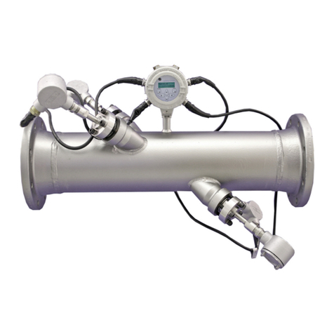
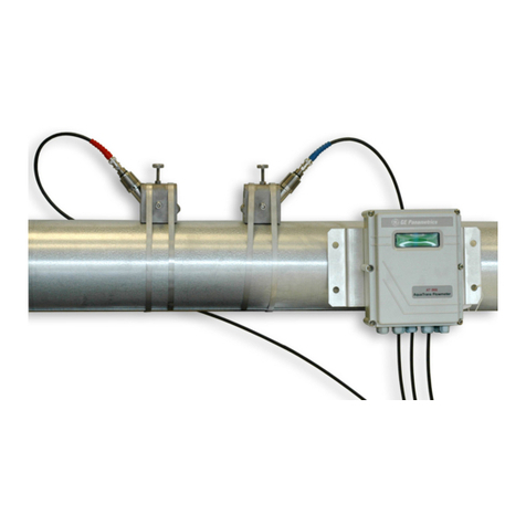
GE PanaFlow XMT1000 User manual

GE
Oil & Gas Flow
910-313 Rev. A
June 2017
PanaFlow™ XMT1000
User’s Manual


www.gemeasurement.com
©2017 General Electric Company. All rights reserved.
Technical content subject to change without notice.
GE
Oil & Gas
PanaFlow™ XMT1000
Panametrics Liquid Flow Ultrasonic Transmitter
User’s Manual
910-313 Rev. A
June 2017

ii
[no content intended for this page]

PanaFlow™ XMT1000 User’s Manual iii
Contents
Product Registration . . . . . . . . . . . . . . . . . . . . . . . . . . . . . . . . . . . . . . . . . . . . . . . . . . . . . . . . . . . . . . . . . . . . . . . . . . . . . . . . . . . . . . . . vii
Services . . . . . . . . . . . . . . . . . . . . . . . . . . . . . . . . . . . . . . . . . . . . . . . . . . . . . . . . . . . . . . . . . . . . . . . . . . . . . . . . . . . . . . . . . . . . . . . . . . . . vii
Terms and Conditions. . . . . . . . . . . . . . . . . . . . . . . . . . . . . . . . . . . . . . . . . . . . . . . . . . . . . . . . . . . . . . . . . . . . . . . . . . . . . . . . . . . . . . . vii
Typographical Conventions . . . . . . . . . . . . . . . . . . . . . . . . . . . . . . . . . . . . . . . . . . . . . . . . . . . . . . . . . . . . . . . . . . . . . . . . . . . . . . . . . vii
Safety Issues . . . . . . . . . . . . . . . . . . . . . . . . . . . . . . . . . . . . . . . . . . . . . . . . . . . . . . . . . . . . . . . . . . . . . . . . . . . . . . . . . . . . . . . . . . . . . . . vii
Auxiliary Equipment. . . . . . . . . . . . . . . . . . . . . . . . . . . . . . . . . . . . . . . . . . . . . . . . . . . . . . . . . . . . . . . . . . . . . . . . . . . . . . . . . . . . . . . . viii
Environmental Compliance. . . . . . . . . . . . . . . . . . . . . . . . . . . . . . . . . . . . . . . . . . . . . . . . . . . . . . . . . . . . . . . . . . . . . . . . . . . . . . . . . . ix
Chapter 1. Installation
1.1 Introduction. . . . . . . . . . . . . . . . . . . . . . . . . . . . . . . . . . . . . . . . . . . . . . . . . . . . . . . . . . . . . . . . . . . . . . . . . . . . . . . . . . . . . . . . . . . .1
1.2 CE Marking Compliance. . . . . . . . . . . . . . . . . . . . . . . . . . . . . . . . . . . . . . . . . . . . . . . . . . . . . . . . . . . . . . . . . . . . . . . . . . . . . . . . .1
1.3 Unpacking the XMT1000 . . . . . . . . . . . . . . . . . . . . . . . . . . . . . . . . . . . . . . . . . . . . . . . . . . . . . . . . . . . . . . . . . . . . . . . . . . . . . . . .2
1.4 Site and Clearance Considerations . . . . . . . . . . . . . . . . . . . . . . . . . . . . . . . . . . . . . . . . . . . . . . . . . . . . . . . . . . . . . . . . . . . . . .3
1.4.1 Access to the Meter . . . . . . . . . . . . . . . . . . . . . . . . . . . . . . . . . . . . . . . . . . . . . . . . . . . . . . . . . . . . . . . . . . . . . . . . . . . . . . .3
1.4.2 Vibration Exposure Considerations . . . . . . . . . . . . . . . . . . . . . . . . . . . . . . . . . . . . . . . . . . . . . . . . . . . . . . . . . . . . . . . . .4
1.4.3 Sunlight Exposure . . . . . . . . . . . . . . . . . . . . . . . . . . . . . . . . . . . . . . . . . . . . . . . . . . . . . . . . . . . . . . . . . . . . . . . . . . . . . . . . .4
1.4.4 Local Mounting. . . . . . . . . . . . . . . . . . . . . . . . . . . . . . . . . . . . . . . . . . . . . . . . . . . . . . . . . . . . . . . . . . . . . . . . . . . . . . . . . . . .5
1.4.5 Remote Mounting . . . . . . . . . . . . . . . . . . . . . . . . . . . . . . . . . . . . . . . . . . . . . . . . . . . . . . . . . . . . . . . . . . . . . . . . . . . . . . . . .6
1.4.6 Cable Lengths. . . . . . . . . . . . . . . . . . . . . . . . . . . . . . . . . . . . . . . . . . . . . . . . . . . . . . . . . . . . . . . . . . . . . . . . . . . . . . . . . . . . .6
1.4.7 Transducer Cables . . . . . . . . . . . . . . . . . . . . . . . . . . . . . . . . . . . . . . . . . . . . . . . . . . . . . . . . . . . . . . . . . . . . . . . . . . . . . . . .6
1.5 Making the Electrical Connections. . . . . . . . . . . . . . . . . . . . . . . . . . . . . . . . . . . . . . . . . . . . . . . . . . . . . . . . . . . . . . . . . . . . . . .7
1.5.1 Wiring the Analog Outputs. . . . . . . . . . . . . . . . . . . . . . . . . . . . . . . . . . . . . . . . . . . . . . . . . . . . . . . . . . . . . . . . . . . . . . . . .9
1.5.2 Wiring the Digital Output . . . . . . . . . . . . . . . . . . . . . . . . . . . . . . . . . . . . . . . . . . . . . . . . . . . . . . . . . . . . . . . . . . . . . . . . .10
1.5.3 Wiring the Modbus/Service Port. . . . . . . . . . . . . . . . . . . . . . . . . . . . . . . . . . . . . . . . . . . . . . . . . . . . . . . . . . . . . . . . . . .11
1.5.4 Wiring the Line Power . . . . . . . . . . . . . . . . . . . . . . . . . . . . . . . . . . . . . . . . . . . . . . . . . . . . . . . . . . . . . . . . . . . . . . . . . . . .12
Chapter 2. Programming
2.1 Introduction. . . . . . . . . . . . . . . . . . . . . . . . . . . . . . . . . . . . . . . . . . . . . . . . . . . . . . . . . . . . . . . . . . . . . . . . . . . . . . . . . . . . . . . . . . .13
2.2 Using the Magnetic Keypad . . . . . . . . . . . . . . . . . . . . . . . . . . . . . . . . . . . . . . . . . . . . . . . . . . . . . . . . . . . . . . . . . . . . . . . . . . . .13
2.3 Passcodes . . . . . . . . . . . . . . . . . . . . . . . . . . . . . . . . . . . . . . . . . . . . . . . . . . . . . . . . . . . . . . . . . . . . . . . . . . . . . . . . . . . . . . . . . . . .14
2.4 Glossary of Terms . . . . . . . . . . . . . . . . . . . . . . . . . . . . . . . . . . . . . . . . . . . . . . . . . . . . . . . . . . . . . . . . . . . . . . . . . . . . . . . . . . . . .15
2.5 Menu Maps . . . . . . . . . . . . . . . . . . . . . . . . . . . . . . . . . . . . . . . . . . . . . . . . . . . . . . . . . . . . . . . . . . . . . . . . . . . . . . . . . . . . . . . . . . .16
Chapter 3. Error Codes and Troubleshooting
3.1 Error Display in the User Interface . . . . . . . . . . . . . . . . . . . . . . . . . . . . . . . . . . . . . . . . . . . . . . . . . . . . . . . . . . . . . . . . . . . . . .25
3.1.1 Error Header . . . . . . . . . . . . . . . . . . . . . . . . . . . . . . . . . . . . . . . . . . . . . . . . . . . . . . . . . . . . . . . . . . . . . . . . . . . . . . . . . . . . .25
3.1.2 Communication Error String . . . . . . . . . . . . . . . . . . . . . . . . . . . . . . . . . . . . . . . . . . . . . . . . . . . . . . . . . . . . . . . . . . . . . .25
3.1.3 Flow Error String . . . . . . . . . . . . . . . . . . . . . . . . . . . . . . . . . . . . . . . . . . . . . . . . . . . . . . . . . . . . . . . . . . . . . . . . . . . . . . . . .26
3.2 Diagnostics . . . . . . . . . . . . . . . . . . . . . . . . . . . . . . . . . . . . . . . . . . . . . . . . . . . . . . . . . . . . . . . . . . . . . . . . . . . . . . . . . . . . . . . . . . .27
3.2.1 Introduction. . . . . . . . . . . . . . . . . . . . . . . . . . . . . . . . . . . . . . . . . . . . . . . . . . . . . . . . . . . . . . . . . . . . . . . . . . . . . . . . . . . . . .27
3.2.2 Flowcell Problems . . . . . . . . . . . . . . . . . . . . . . . . . . . . . . . . . . . . . . . . . . . . . . . . . . . . . . . . . . . . . . . . . . . . . . . . . . . . . . . .27
3.2.3 Transducer/Buffer Problems . . . . . . . . . . . . . . . . . . . . . . . . . . . . . . . . . . . . . . . . . . . . . . . . . . . . . . . . . . . . . . . . . . . . . .29

Contents
iv PanaFlow™ XMT1000 User’s Manual
Appendix A. Specifications
A.1 Operation and Performance . . . . . . . . . . . . . . . . . . . . . . . . . . . . . . . . . . . . . . . . . . . . . . . . . . . . . . . . . . . . . . . . . . . . . . . . . . .31
A.2 Electronics . . . . . . . . . . . . . . . . . . . . . . . . . . . . . . . . . . . . . . . . . . . . . . . . . . . . . . . . . . . . . . . . . . . . . . . . . . . . . . . . . . . . . . . . . . . .32
Appendix B. Modbus Communication
B.1 Modbus Protocol . . . . . . . . . . . . . . . . . . . . . . . . . . . . . . . . . . . . . . . . . . . . . . . . . . . . . . . . . . . . . . . . . . . . . . . . . . . . . . . . . . . . . .35
B.2 Modbus Register Map . . . . . . . . . . . . . . . . . . . . . . . . . . . . . . . . . . . . . . . . . . . . . . . . . . . . . . . . . . . . . . . . . . . . . . . . . . . . . . . . .35
Appendix C. HART Communication
C.1 Wiring the XMT1000 to the HART Communicator. . . . . . . . . . . . . . . . . . . . . . . . . . . . . . . . . . . . . . . . . . . . . . . . . . . . . . . .53
C.2 HART Write Mode Switch . . . . . . . . . . . . . . . . . . . . . . . . . . . . . . . . . . . . . . . . . . . . . . . . . . . . . . . . . . . . . . . . . . . . . . . . . . . . . .53
C.3 HART Menu Maps . . . . . . . . . . . . . . . . . . . . . . . . . . . . . . . . . . . . . . . . . . . . . . . . . . . . . . . . . . . . . . . . . . . . . . . . . . . . . . . . . . . . .54
C.3.1 HART Output Menu Map. . . . . . . . . . . . . . . . . . . . . . . . . . . . . . . . . . . . . . . . . . . . . . . . . . . . . . . . . . . . . . . . . . . . . . . . . .54
C.3.2 HART Review Menu Map. . . . . . . . . . . . . . . . . . . . . . . . . . . . . . . . . . . . . . . . . . . . . . . . . . . . . . . . . . . . . . . . . . . . . . . . . .55
Appendix D. Foundation Fieldbus Communication
D.1 Introduction. . . . . . . . . . . . . . . . . . . . . . . . . . . . . . . . . . . . . . . . . . . . . . . . . . . . . . . . . . . . . . . . . . . . . . . . . . . . . . . . . . . . . . . . . . .57
D.2 Installation. . . . . . . . . . . . . . . . . . . . . . . . . . . . . . . . . . . . . . . . . . . . . . . . . . . . . . . . . . . . . . . . . . . . . . . . . . . . . . . . . . . . . . . . . . . .57
D.2.1 Network Configuration . . . . . . . . . . . . . . . . . . . . . . . . . . . . . . . . . . . . . . . . . . . . . . . . . . . . . . . . . . . . . . . . . . . . . . . . . . .57
D.2.2 Polarity. . . . . . . . . . . . . . . . . . . . . . . . . . . . . . . . . . . . . . . . . . . . . . . . . . . . . . . . . . . . . . . . . . . . . . . . . . . . . . . . . . . . . . . . . .57
D.2.3 Connection . . . . . . . . . . . . . . . . . . . . . . . . . . . . . . . . . . . . . . . . . . . . . . . . . . . . . . . . . . . . . . . . . . . . . . . . . . . . . . . . . . . . . .58
D.2.4 FISCO (Fieldbus Intrinsically Safe Concept). . . . . . . . . . . . . . . . . . . . . . . . . . . . . . . . . . . . . . . . . . . . . . . . . . . . . . . . .58
D.2.5 DD File . . . . . . . . . . . . . . . . . . . . . . . . . . . . . . . . . . . . . . . . . . . . . . . . . . . . . . . . . . . . . . . . . . . . . . . . . . . . . . . . . . . . . . . . . .60
D.2.6 Default Node Address . . . . . . . . . . . . . . . . . . . . . . . . . . . . . . . . . . . . . . . . . . . . . . . . . . . . . . . . . . . . . . . . . . . . . . . . . . . .60
D.3 Specifications . . . . . . . . . . . . . . . . . . . . . . . . . . . . . . . . . . . . . . . . . . . . . . . . . . . . . . . . . . . . . . . . . . . . . . . . . . . . . . . . . . . . . . . . .61
D.3.1 General . . . . . . . . . . . . . . . . . . . . . . . . . . . . . . . . . . . . . . . . . . . . . . . . . . . . . . . . . . . . . . . . . . . . . . . . . . . . . . . . . . . . . . . . .61
D.3.2 Physical . . . . . . . . . . . . . . . . . . . . . . . . . . . . . . . . . . . . . . . . . . . . . . . . . . . . . . . . . . . . . . . . . . . . . . . . . . . . . . . . . . . . . . . . .61
D.3.3 Communication . . . . . . . . . . . . . . . . . . . . . . . . . . . . . . . . . . . . . . . . . . . . . . . . . . . . . . . . . . . . . . . . . . . . . . . . . . . . . . . . .61
D.3.4 User Layer. . . . . . . . . . . . . . . . . . . . . . . . . . . . . . . . . . . . . . . . . . . . . . . . . . . . . . . . . . . . . . . . . . . . . . . . . . . . . . . . . . . . . . .62
D.3.5 Function Blocks. . . . . . . . . . . . . . . . . . . . . . . . . . . . . . . . . . . . . . . . . . . . . . . . . . . . . . . . . . . . . . . . . . . . . . . . . . . . . . . . . .62
D.4 Resource Block. . . . . . . . . . . . . . . . . . . . . . . . . . . . . . . . . . . . . . . . . . . . . . . . . . . . . . . . . . . . . . . . . . . . . . . . . . . . . . . . . . . . . . . .63
D.4.1 FF Revision . . . . . . . . . . . . . . . . . . . . . . . . . . . . . . . . . . . . . . . . . . . . . . . . . . . . . . . . . . . . . . . . . . . . . . . . . . . . . . . . . . . . . .63
D.4.2 Password. . . . . . . . . . . . . . . . . . . . . . . . . . . . . . . . . . . . . . . . . . . . . . . . . . . . . . . . . . . . . . . . . . . . . . . . . . . . . . . . . . . . . . . .64
D.4.3 NAMUR NE107. . . . . . . . . . . . . . . . . . . . . . . . . . . . . . . . . . . . . . . . . . . . . . . . . . . . . . . . . . . . . . . . . . . . . . . . . . . . . . . . . . .65
D.5 XMIT Transducer Block . . . . . . . . . . . . . . . . . . . . . . . . . . . . . . . . . . . . . . . . . . . . . . . . . . . . . . . . . . . . . . . . . . . . . . . . . . . . . . . .67
D.5.1 Units . . . . . . . . . . . . . . . . . . . . . . . . . . . . . . . . . . . . . . . . . . . . . . . . . . . . . . . . . . . . . . . . . . . . . . . . . . . . . . . . . . . . . . . . . . . .68
D.6 Composite Transducer Block. . . . . . . . . . . . . . . . . . . . . . . . . . . . . . . . . . . . . . . . . . . . . . . . . . . . . . . . . . . . . . . . . . . . . . . . . . .69
D.6.1 Clearing the Totalizer . . . . . . . . . . . . . . . . . . . . . . . . . . . . . . . . . . . . . . . . . . . . . . . . . . . . . . . . . . . . . . . . . . . . . . . . . . . .72
D.7 Channel Transducer Block . . . . . . . . . . . . . . . . . . . . . . . . . . . . . . . . . . . . . . . . . . . . . . . . . . . . . . . . . . . . . . . . . . . . . . . . . . . . .73
D.8 Analog Input Block . . . . . . . . . . . . . . . . . . . . . . . . . . . . . . . . . . . . . . . . . . . . . . . . . . . . . . . . . . . . . . . . . . . . . . . . . . . . . . . . . . . .75
D.9 PID Block . . . . . . . . . . . . . . . . . . . . . . . . . . . . . . . . . . . . . . . . . . . . . . . . . . . . . . . . . . . . . . . . . . . . . . . . . . . . . . . . . . . . . . . . . . . . .75

PanaFlow™ XMT1000 User’s Manual v
Contents
D.10 Error Handling. . . . . . . . . . . . . . . . . . . . . . . . . . . . . . . . . . . . . . . . . . . . . . . . . . . . . . . . . . . . . . . . . . . . . . . . . . . . . . . . . . . . . . . . .76
D.11 Simulation Mode . . . . . . . . . . . . . . . . . . . . . . . . . . . . . . . . . . . . . . . . . . . . . . . . . . . . . . . . . . . . . . . . . . . . . . . . . . . . . . . . . . . . . .78
D.12 Fieldbus Troubleshooting Guide . . . . . . . . . . . . . . . . . . . . . . . . . . . . . . . . . . . . . . . . . . . . . . . . . . . . . . . . . . . . . . . . . . . . . . . .79
D.13 DPI620 FF Modular Communicator . . . . . . . . . . . . . . . . . . . . . . . . . . . . . . . . . . . . . . . . . . . . . . . . . . . . . . . . . . . . . . . . . . . . .80
Index. . . . . . . . . . . . . . . . . . . . . . . . . . . . . . . . . . . . . . . . . . . . . . . . . . . . . . . . . . . . . . . . . . . . . . . . . . . . . . . . . . . . . . . . . . . . . . . . . . . . . . .81

Contents
vi PanaFlow™ XMT1000 User’s Manual
[no content intended for this page]

PanaFlow™ XMT1000 User’s Manual vii
Preface
Product Registration
Thank you for purchasing a model PanaFlow™ XMT1000 from GE. Please register your product at
www.gemeasurement.com/productregistration for product support such as the latest software/firmware upgrades,
product information and special promotions.
Services
GE provides customers with an experienced staff of customer support personnel ready to respond to technical inquiries,
as well as other remote and on-site support needs. To complement our broad portfolio of industry-leading solutions, we
offer several types of flexible and scalable support services including: Training, Product Repairs, Service Agreements
and more. Please visit www.gemeasurement.com/services for more details.
Terms and Conditions
GE’s sales Terms and Conditions for your recent purchase of a GE product, including the applicable product Warranty,
can be found on our website at the following link: www.gemeasurement.com/sales-terms-and-conditions
Typographical Conventions
Note: These paragraphs provide information that provides a deeper understanding of the situation, but is not
essential to the proper completion of the instructions.
IMPORTANT: These paragraphs provide information that emphasizes instructions that are essential to proper setup of
the equipment. Failure to follow these instructions carefully may cause unreliable performance.
Safety Issues
CAUTION! This symbol indicates a risk of potential minor personal injury and/or severe damage to
the equipment, unless these instructions are followed carefully.
WARNING! This symbol indicates a risk of potential serious personal injury, unless these instructions
are followed carefully.
WARNING! It is the responsibility of the user to make sure all local, county, state and national codes,
regulations, rules and laws related to safety and safe operating conditions are met for each
installation.
Attention European Customers! To meet CE Marking requirements for all units intended for use in
the EU, all electrical cables must be installed as described in this manual.

Preface
viii PanaFlow™ XMT1000 User’s Manual
Auxiliary Equipment
Local Safety Standards
The user must make sure that he operates all auxiliary equipment in accordance with local codes, standards,
regulations, or laws applicable to safety.
Working Area
Qualification of Personnel
Make sure that all personnel have manufacturer-approved training applicable to the auxiliary equipment.
Personal Safety Equipment
Make sure that operators and maintenance personnel have all safety equipment applicable to the auxiliary equipment.
Examples include safety glasses, protective headgear, safety shoes, etc.
Unauthorized Operation
Make sure that unauthorized personnel cannot gain access to the operation of the equipment.
WARNING! Auxiliary equipment may have both manual and automatic modes of operation. As
equipment can move suddenly and without warning, do not enter the work cell of this equipment
during automatic operation, and do not enter the work envelope of this equipment during manual
operation. If you do, serious injury can result.
WARNING! Make sure that power to the auxiliary equipment is turned OFF and locked out before
you perform maintenance procedures on this equipment.

PanaFlow™ XMT1000 User’s Manual ix
Preface
Environmental Compliance
RoHS
The PanaFlow™ XMT1000 fully complies with RoHS regulations (Directive 2011/65/EU).
Waste Electrical and Electronic Equipment (WEEE) Directive
GE is an active participant in Europe’s Waste Electrical and Electronic Equipment (WEEE) take-back initiative
(Directive 2012/19/EU).
The equipment that you bought has required the extraction and use of natural resources for its production. It may
contain hazardous substances that could impact health and the environment.
In order to avoid the dissemination of those substances in our environment and to diminish the pressure on the natural
resources, we encourage you to use the appropriate take-back systems. Those systems will reuse or recycle most of the
materials of your end life equipment in a sound way.
The crossed-out wheeled bin symbol invites you to use those systems.
If you need more information on the collection, reuse and recycling systems, please contact your local or regional
waste administration.
Please visit http://www.gemeasurement.com/environmental-health-safety-ehs for take-back instructions and more
information about this initiative.

Preface
xPanaFlow™ XMT1000 User’s Manual
[no content intended for this page]

PanaFlow™ XMT1000 User’s Manual 1
Chapter 1. Installation
1.1 Introduction
To ensure safe and reliable operation of the XMT1000, it must be installed in accordance with the established
guidelines. Those guidelines, explained in detail in this chapter, include the following topics:
•Unpacking the XMT1000
•Selecting the location for the XMT1000 (local or remote)
•Installing the XMT1000 at the selected location
•Wiring the XMT1000
1.2 CE Marking Compliance
For CE Marking compliance or installation in high noise areas, the XMT1000 flow transmitter must be wired in
accordance with the instructions in this section.
IMPORTANT: CE Marking compliance is required for all units intended for use in EU countries.
The XMT1000 must be wired with the recommended cable, and all connections must be properly shielded and
grounded. Grounding of the chassis must be within 10 ft (3 m) of the transmitter. Refer to Table 1 below for the specific
requirements.
Note: If the XMT1000 is wired as described above, the unit will comply with the EMC and LVD Directives.
WARNING! The XMT1000 flow transmitter can measure the flow rate of many fluids, some of which
are potentially hazardous. The importance of proper safety practices cannot be overemphasized.
Be sure to follow all applicable local safety codes and regulations for installing electrical equipment
and working with hazardous fluids or flow conditions. Consult company safety personnel or local
safety authorities to verify the safety of any procedure or practice.
Attention European Customers! To meet CE Marking requirements, all cables must be installed as
described in “CE Marking Compliance” on page 1.
Table 1: Wiring Requirements
Connection Cable Type Ground Termination
Transducer Armored RG-62 a/U or equivalent Grounded using a cable gland.
Input/Output Armored 22 AWG shielded with armored material added to
outside of jacket
Grounded using a cable gland.
Power Armored 14 AWG 2 conductor Grounded using a cable gland.

Chapter 1. Installation
2PanaFlow™ XMT1000 User’s Manual
1.3 Unpacking the XMT1000
Before removing the XMT1000 from its box, please inspect both the box and the instrument carefully. Each instrument
manufactured by GE is warranted to be free from defects in material and workmanship. Before discarding any of the
packing materials, account for all components and documentation listed on the packing slip. The discarding of an
important item along with the packing materials is all too common. If anything is missing or damaged, contact GE
Customer Care immediately for assistance.
The XMT1000 is supplied with both a serial number label and a certification label for identification of the instrument
(see Figure 1 below and Figure 2 on page 3). The system can be mounted either on an existing meter body (local
mounting) or at another location via a connecting cable (remote mounting).
Figure 1: Typical XMT1000 Labels (Aluminum Enclosure)
Model & Serial Number (Boston) Model & Serial Number (Shannon)
Certification (US/CAN, IECEx/ATEX)
[FISCO]
Certification (US/CAN, IECEx/ATEX)
[Standard]

PanaFlow™ XMT1000 User’s Manual 3
Chapter 1. Installation
1.3 Unpacking the XMT1000 (cont.)
Figure 2: Typical XMT1000 Labels (Stainless Steel Enclosure)
1.4 Site and Clearance Considerations
1.4.1 Access to the Meter
Because the relative location of the flowcell and the XMT1000 transmitter is important, use the guidelines in this
section to plan the XMT1000 installation.
For flowcell clearance recommendations, consult the manual for your specific flow meter system or contact GE for
assistance. Access to the XMT1000 flow transmitter should be uninhibited, as defined by the minimum clearance
distances around the enclosure specified in Figure 3 on page 4.
Model & Serial Number (Boston) Model & Serial Number (Shannon)
Certification (US/CAN, IECEx/ATEX)
[FISCO]
Certification (US/CAN, IECEx/ATEX)
[Standard]

Chapter 1. Installation
4PanaFlow™ XMT1000 User’s Manual
1.4.1 Access to the Meter (cont.)
Figure 3: XMT1000 Enclosure Clearances (ref. dwg. 712-2164)
1.4.2 Vibration Exposure Considerations
Whenever possible, install the XMT1000 flow transmitter in a location isolated from vibrations. Avoid installing it near
equipment that generates low-frequency, high-energy random vibrations.
1.4.3 Sunlight Exposure
The installer should consider and limit exposure of the XMT1000 flow transmitter to direct sunlight. Sunshades should
be utilized in extreme environments.
1000 SERIES ELECTRONICS
12 in. (300 mm) CLEARANCE
MINIMUM RECOMMENDED
FOR CABLE ENTRY
12 in. (300 mm) CLEARANCE
MINIMUM RECOMMENDED
FOR CABLE ENTRY
12 in. (300 mm) CLEARANCE
MINIMUM RECOMMENDED
FOR SERVICE ACCESS
12 in. (300 mm) CLEARANCE
MINIMUM RECOMMENDED
FOR SERVICE ACCESS
12 in. (300 mm) CLEARANCE
MINIMUM RECOMMENDED
FOR CABLE ENTRY
CUSTOMER SUPPLIED 2” PIPE
1000 SERIES
REMOTE MOUNT KIT

PanaFlow™ XMT1000 User’s Manual 5
Chapter 1. Installation
1.4.4 Local Mounting
The XMT1000 accuracy is affected by the flowcell location in the process piping and on the orientation of the
transducers. Thus, in addition to accessibility for maintenance, adhere to the following installation guidelines:
•Locate the flowcell so that there are at least 10 pipe diameters of straight, undisturbed flow upstream and
5 pipe diameters of straight, undisturbed flow downstream from the measurement point (see Figure 4 below).
Undisturbed flow means avoiding sources of turbulence in the fluid (e.g., valves, flanges, expansions, elbows,
etc.), avoiding swirl, and avoiding cavitation.
Figure 4: Minimum Straight Run Pipe Requirements
•Locate the transducers on a common axial plane along the pipe. Also, locate them on the side of the pipe
instead of on the top or the bottom, because the top of the pipe tends to accumulate gas and the bottom tends to
accumulate sediment. Either condition will cause unwanted attenuation of the ultrasonic signals. There is no
similar restriction with vertical pipes, as long as the fluid flow is upward to prevent free falling of the fluid or a
less than full pipe (see Figure 5 below).
Figure 5: Good and Bad Flowcell/Transducer Orientations
CAUTION! Do not place thermal insulation on or around the transducers, the junction boxes, or the
meter electronics. The transducer and junction box act as a heat sink that protects the transducer
from high and low temperatures.
Flow Direction
10D 5D
BAD
Vertical
GOOD
Flow Direction
Flow Direction
Flowcell
Flow Direction
GOOD
BAD
Horizontal
Flowcell

Chapter 1. Installation
6PanaFlow™ XMT1000 User’s Manual
1.4.5 Remote Mounting
The standard XMT1000 enclosure is a powder-coated, aluminum, IP67 explosion-proof enclosure. Typically, the
enclosure is mounted as close as possible to the transducers. When choosing a site for a remote-mount installation,
which is recommended for process temperatures exceeding 150°C, make sure the location permits easy access to the
enclosure for programming, maintenance and service.
1.4.6 Cable Lengths
Locate the XMT1000 as close as possible to the transducers. The maximum distance from the transducers for remote
mounting of the XMT1000 is 1000 ft (300 m) using RG-62 coaxial cable or equivalent. If longer distances are required,
consult the factory for assistance.
1.4.7 Transducer Cables
When installing the transducer cables, always observe established standard practices for the installation of electrical
cables. Do not route transducer cables alongside high amperage AC power lines or any other cables that could cause
electrical interference. Also, protect the transducer cables and connections from the weather and corrosive
atmospheres, and be sure to follow the manufacturer's installation guidelines if cable glands are provided.
Attention European Customers! For compliance with the European Union’s Low Voltage Directive,
this unit requires an external power disconnect device such as a switch or circuit breaker. The
disconnect device must be marked as such, clearly visible, directly accessible, and located within
1.8 m (6 ft) of the unit.

PanaFlow™ XMT1000 User’s Manual 7
Chapter 1. Installation
1.5 Making the Electrical Connections
This section contains instructions for making all the necessary electrical connections for the XMT1000 flow
transmitter. Refer to Figure 6 on page 8 for a complete wiring diagram.
Note: Both flying lead and MCX transducer connectors are shown in the figure for completeness. Only the type of
connector appropriate for each meter ordered will be installed on the PCB.
Prepare the XMT1000 for wiring by completing the following steps:
•To access the wiring terminals, complete the following steps:
1. Disconnect any previously wired power line from the unit.
2. Loosen the set screw on the wiring cover.
3. Place a rod or long screwdriver across the cover in the slots provided, and rotate the cover counterclockwise
until it comes free from the enclosure.
4. Install any required cable glands in the appropriate conduit holes on the opposite side of the enclosure.
5. Note the labels inside the rear cover to assist in wiring the power and option connections.
•Wiring any option set requires completion of the following general steps:
1. Disconnect the main power from the unit and remove the wiring cover.
2. Install a cable gland in the chosen conduit hole on the side of the electronics enclosure and feed a standard
26-12 AWG twisted-pair cable through this conduit hole.
3. Locate the Standard I/O or Analog I/O options terminal block and wire the option as indicated on the label
inside the wiring cover. Secure the cable gland.
4. If wiring of the unit has been completed, reinstall the wiring cover on the enclosure and tighten the set screw.
For specific instructions on wiring a particular output configuration, proceed to the appropriate sub-section.
WARNING! Always disconnect the line power from the XMT1000 before removing either the front
cover or the rear cover. This is especially important in a hazardous environment.
Attention European Customers! To meet CE Marking requirements, all cables must be installed as
described in “CE Marking Compliance” on page 1.
WARNING! Proper grounding of the XMT1000 enclosure via the external grounding screw on the
enclosure (see Figure 6 on page 8) is required to prevent the possibility of electric shock. All ground
screws should be hand tightened only, to a maximum allowable torque of 2.5 N-m (22 in-lb).

Chapter 1. Installation
8PanaFlow™ XMT1000 User’s Manual
1.5 Making the Electrical Connections (cont.)
Figure 6: XMT1000 Terminal Board Wiring Diagram (ref. dwg. 702-2040)
CH2 FLYING LEAD TERMINAL BLOCK (TB6)
ACCEPTS 26-12 AWG WIRE
PIN DESCRIPTION
1 CH 2 DOWNSTREAM SIG (+)
2 CH 2 DOWNSTREAM RTN (-)
3 CH 2 UPSTREAM RTN (-)
4 CH 2 UPSTREAM SIG (+)
CH1 FLYING LEAD TERMINAL BLOCK (TB5)
ACCEPTS 26-12 AWG WIRE
PIN DESCRIPTION
1 CH 1 DOWNSTREAM SIG (+)
2 CH 1 DOWNSTREAM RTN (-)
3 CH 1 UPSTREAM RTN (-)
4 CH 1 UPSTREAM SIG (+)
MCX TERMINAL CONNECTORS
ACCEPTS 50 RIGHT ANGLE MCX PLUG
PIN DESCRIPTION
UP1 CH 1 UPSTREAM
DN1 CH 1 DOWNSTREAM
UP2 CH 2 UPSTREAM
DN2 CH 2 DOWNSTREAM
UP3 CH 3 UPSTREAM
DN3 CH 3 DOWNSTREAM
*ENCLOSURE MAIN CUSTOMER GROUND
STANDARD I/O TERMINAL BLOCK (TB3)
ACCEPTS 26-12 AWG WIRE
PIN DESCRIPTION
1 RS485 MODBUS (+)
2 RS485 MODBUS (-)
3 RS485 COMMON
4 FREQUENCY/TOTALIZER/CAL (+)
5 FREQUENCY/TOTALIZER/CAL (-)
6 ANALOG 4-20MA OUT (+)
7 ANALOG 4-20MA RTN (-)
ADDITIONAL CUSTOMER GROUND, 3X
PCB GROUND
DIGITAL COMMUNICATION
TERMINAL BLOCK (TB1)
NONE, [OR]
+$577(50,1$/%/2&.
ACCEPTS 26-12 AWG WIRE
PIN DESCRIPTION
1 HART (+)
2 HART (-)
[OR]
)281'$7,21),(/'%86
ACCEPTS 26-12 AWG WIRE
PIN DESCRIPTION
1 FIELDBUS NET (+)
2 FIELDBUS NET (-)
ANALOG I/O TERMINAL BLOCK (TB2)
ACCEPTS 26-12 AWG WIRE
FOR FUTURE USE
LINE POWER TERMINAL BLOCK (TB4)
ACCEPTS 20-10 AWG WIRE
$&
PIN DESCRIPTION
1 (L1) LINE
2 (L2/N) NEUTRAL
* CONNECT GROUND TO CHASSIS
[OR]
'&
PIN DESCRIPTION
1 +
2 -
* CONNECT GROUND TO CHASSIS
CASTED GROUND SYMBOL
EXTERIOR GROUND SCREW
[TB1]
[TB2]
[TB3]
[TB4]
[TB5] [TB6]
Table of contents
Other GE Transmitter manuals
Popular Transmitter manuals by other brands

Amana
Amana DT01* installation instructions

Scott Instruments
Scott Instruments 4688IR Series Safety, Setup, Operation & Maintenance Manual

Quick
Quick HT8 Manual of installation and use

Globalstar
Globalstar ST100 quick start guide

Telran communications
Telran communications OPIA00001 user manual

JTS
JTS IN-64TH instruction manual

Absolute Process Instruments
Absolute Process Instruments APD 7010 quick start guide

Hall Technologies
Hall Technologies DSCV1-70-TX user manual

Manta
Manta FMT002 user manual

AFi
AFi MT-1 instruction manual

Invisible
Invisible QC0144 installation manual

RKI Instruments
RKI Instruments 65-2330RK Operator's manual