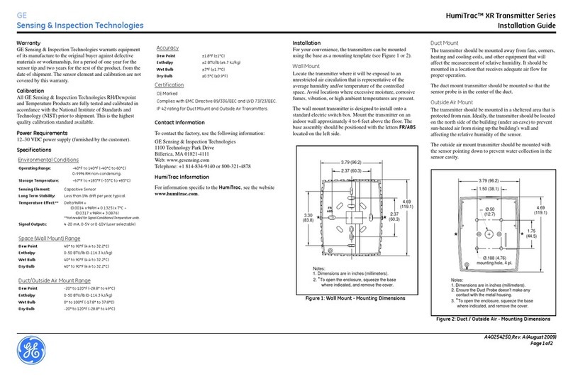
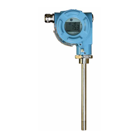
GE Hart Druck RTX 1000H Series User manual

Druck RTX 1000H series
HART®Pressure transmitter
User manual - K0297
GE
Sensing & Inspection Technologies


Customer service
Visit our web site: www.gesensinginspection.com
Publication: K0297 Issue 2
© 2009 General Electric Company. All rights reserved.


RTX 1000H series user manual
i K0297 Issue 2
Safety
To use this equipment safely, you must use the data and procedures in these
publications:
• The “Calibration data and instructions” for the equipment
• This user manual
These publications contain instructions to operate the equipment and maintain
it in a safe condition. To prevent damage or injury:
• Obey all warnings and cautions.
• Use the equipment only for the specified applications.
• Operate the equipment only in the specified limits.
To install and use the equipment, use only approved engineers who have the
necessary skills and qualifications.
Hazardous areas
Some versions of this equipment are certified for use in hazardous areas (the
ATEX Directive 94/9/EC - Equipment and Protective Systems Intended for Use
in Potentially Explosive Atmospheres). For these versions, the publication
“Calibration data and instructions” contains additional data. The additional data
includes some or all of these items:
• Marking details
• Materials
•Installation
• Configuration/Calibration (or Connections to other equipment)
• Maintenance
• Repair
• Special conditions for safe use
This product complies with the requirements of the relevant EEC
directives. For data on the applied standards, refer to the “Declaration
of Conformity”.
Trademarks
All product names are trademarks of their respective companies.

RTX 1000H series user manual
K0297 Issue 2 ii
Abbreviations
The abbreviations in this publication are as follows:
Note: Abbreviations are the same in the singular and plural.
a absolute pressure
A/D analogue to digital
ATEX ATmosphères EXplosibles (explosive atmospheres)
AWG American wire gage
COSHH Control of Substances Hazardous to Health Regulations
D/A digital to analogue
DAC digital to analogue convertor
DIN Deutsche Industrie Norm
DIP dual inline package
DPM digital pressure module
°C degrees Celsius
°F degrees Fahrenheit
EEPROM electrically erasable programmable read-only memory
EMC electromagnetic compatibility
FS full-scale
g gauge pressure
HART®highway addressable remote transducer
HHC hand held communicator
kg kilogram
lb pound
LCD liquid crystal display
LRL lower range limit
LRV lower range value
mmetre
mA milliampere
max maximum
mbar millibar
µF microfarads

RTX 1000H series user manual
iii K0297 Issue 2
mH millihenry
min minimum/minute
mm millimetre
mmH2O millimetre of water
MWP maximum working pressure
NAMUR Normenarbeitsgemeinschaft für Mess- und Regeltechnik
(An association of users of process control technology)
PCB printed circuit board
psi pound-force per square inch
PTFE polytetrafluoroethylene
PV primary variable
RH relative humidity
RTX Rangeable Transmitter
s seconds
sg specific gravity
TSL terminal straight line
URL upper range limit
URV upper range value
Vvolt
V d.c. volts direct current
Ωohm

RTX 1000H series user manual
K0297 Issue 2 iv
Table of Contents Page
Safety ......................................................................................................... i
Abbreviations ........................................................................................... ii
Table of Contents ..................................................................................... iv
1 DESCRIPTION ...................................................................................... 1-1
1.1 Introduction .................................................................................. 1-1
1.2 About the Electronics Housing ..................................................... 1-1
1.3 Identification Codes ..................................................................... 1-3
2 TECHNICAL DATA .............................................................................. 2-1
2.1 Pressure Ranges ......................................................................... 2-1
2.2 Environment Data ........................................................................ 2-1
2.3 Performance Data ........................................................................ 2-1
2.4 Physical Data ............................................................................... 2-4
3 INSTALLATION .................................................................................... 3-1
3.1 Introduction .................................................................................. 3-1
3.2 Special Tools and Equipment ...................................................... 3-1
3.3 Location and Mounting ................................................................. 3-2
3.4 To Rotate the LCD Module Thru 90° ........................................... 3-2
3.5 To Rotate the Housing ................................................................. 3-3
3.6 Impulse Piping ............................................................................. 3-3
3.7 The Transmitter Pressure Connections ....................................... 3-4
3.8 Liquid Level Measurement ........................................................... 3-6
3.9 Electrical Data .............................................................................. 3-7
3.10 System Checks ............................................................................ 3-10
RTX 1000H series user manual
v K0297 Issue 2
Page
4 OPERATION ......................................................................................... 4-1
4.1 General ........................................................................................ 4-1
4.2 Manual Configuration Facilities .................................................... 4-2
4.3 Manual Configuration - Calibration .............................................. 4-3
4.4 Manual Configuration - LCD ........................................................ 4-6
5 MAINTENANCE .................................................................................... 5-1
5.1 General ........................................................................................ 5-1
5.2 Fault Finding ................................................................................ 5-2
5.3 Returned Goods Procedure ......................................................... 5-4
Safety Precautions ....................................................................... 5-4
Important Notice ........................................................................... 5-4
Customer service ......................................................................... Back cover

RTX 1000H series user manual
K0297 Issue 2 vi
Page
Illustrations
1-1 General view ................................................................................ 1-1
1-2 Transmitter schematic diagram .................................................... 1-2
2-1 Range limits ................................................................................. 2-1
2-2 Dimensions (Transmitter) ............................................................. 2-4
2-3 Dimensions (Optional mounting bracket) ..................................... 2-5
3-1 LCD module - Turn thru 90° ......................................................... 3-2
3-2 Housing locking screws ............................................................... 3-3
3-3 Piping arrangements .................................................................... 3-5
3-4 Open tank level measurement ..................................................... 3-6
3-5 Power and load requirements ...................................................... 3-7
3-6 Electrical conduit configuration .................................................... 3-9
3-7 Transmitter connections ............................................................... 3-9
4-1 Display - Normal operation .......................................................... 4-1
4-2 Location of DIP switches and push buttons ................................. 4-2
4-3 Calibration set-up for safe areas .................................................. 4-3
4-4 LCD - Range selection ................................................................. 4-5
4-5 Selection sequence - LCD configuration ...................................... 4-6
5-1 Fault finding from the output signal .............................................. 5-2
Tables
1-1 Identification codes ...................................................................... 1-4
3-1 Wire resistance ............................................................................ 3-8
4-1 DIP switch operation .................................................................... 4-2
5-1 LCD alarm/error codes ................................................................. 5-3

RTX 1000H series user manual
1-1 K0297 Issue 2
1 DESCRIPTION
1.1 Introduction
The Druck RTX 1000H series is a process pressure transmitter that measures
the pressure of liquid, gas or vapour and gives an analogue output proportional
to the applied pressure. The transmitter is available in a compact and
lightweight metal housing with facilities for direct mounting to pipeline
installations. The type of housing is specified in the order.
The transmitter uses the HART®protocol to give digital two-way
communication. The HART®protocol gives easy access to the process data
and makes it possible to adjust the transmitter operation. For example: to make
accurate adjustments to the zero and span. There are also push-buttons and
switches on the electronics module to adjust the transmitter operation.
1.2 About the Electronics Housing (Figure 1-1)
The electronics housing contains a digital pressure module (DPM), electronics
module, connecting cables and the terminal block.
Figure 1-1: General view
end-cap (with
access to the
terminal block)
electrical
conduit entry name
plate end-cap
(with access to the
electronics module)
housing locking
screw
process pressure
connection
certification
label (If fitted)
electronics
housing

RTX 1000H series user manual
K0297 Issue 2 1-2
Figure 1-2: Transmitter schematic diagram

RTX 1000H series user manual
1-3 K0297 Issue 2
Digital Pressure Module (DPM) - (Figure 1-2)
The sensing element in the DPM is constructed from a micro-machined silicon
diaphragm assembly bonded to a stainless steel or Hastelloy body. A Hastelloy
isolation diaphragm and silicone fluid isolates the sensing element from the
process media.
The sensor piezo-resistors, diffused into the surface of the silicon diaphragm,
produce a signal in response to applied pressure. The accuracy of the sensor
element is enhanced by measuring the residual errors over its operating
temperature and pressure range and applying digital compensation in the
transmitter electronics.
Electronics Module (Figure 1-2)
The electronics module uses microprocessor technology to give a compact
circuit with the minimum of components. The module produces an extremely
stable signal unaffected by changes in ambient temperature.
The HART®communication module gives digital two-way communications. The
HART®protocol gives easy access to the process data and makes it possible
to adjust the transmitter configuration from any point in the loop.
An optional LCD module shows the applied pressure value in two ways:
• as a % of calibrated span represented by a bar graph
• as a value in the applicable engineering units.
The LCD shows the Primary Variable (PV) value for the applied pressure. The
LCD value is not affected by the re-range facilities.
1.3 Identification Codes (Table 1-1)
Table 1-1 shows the identification codes for the transmitter. Before you install
the transmitter, use this table to make sure that the data on the transmitter is
correct.

RTX 1000H series user manual
K0297 Issue 2 1-4
Table 1-1: Identification codes
* Only available with range code 24, process connection code 5, and approval options 0,
I or N.
** Range code 24 (0-1400 bar) only applies to RTX 1020 models.
*** Process connection code 5 (autoclave fitting) only applies to range code 24.
RTX 10 Base Model Number
Code Diaphragm Process Wetted Body Fill Fluid
00 Hastelloy C 316 stainless steel Silicone oil
10 Hastelloy C Hastelloy C Silicone oil
20 Inconel 625 * Inconel 625 * Silicone oil
Code Output
H 4 - 20 mA + HART®
Code Max Span Min Span Notes
07 0 - 2 bar 0 - 20 mbar Gauge or absolute
10 0 - 7 bar 0 - 70 mbar Gauge or absolute
13 0 - 20 bar 0 - 200 mbar Gauge or absolute
16 0 - 70 bar 0 - 700 mbar Gauge or absolute
18 0 - 200 bar 0 - 2 bar Sealed gauge or absolute
22 0 - 700 bar 0 - 7 bar Sealed gauge or absolute
24 0 - 1400 bar ** 0 - 14 bar Sealed gauge or absolute
Code Type
A Absolute
G Gauge (sealed gauge for ranges above 70 bar)
Code Process Connection
1G½female
2 ½-14 NPT female
3 G½ male to BS EN 837-1 (DIN 16288)
4 ½ NPT male
5 9/16" tube Autoclave Engineers medium pressure,
SF562CX20 female ***
Code Electrical Entry
M M20 female
N ½-14 NPT female (via adaptor)
P PG 13.5 female (via adaptor)
Code Electronics Housing End-caps
0 Aluminium Alloy Aluminium Alloy
S Stainless Steel Aluminium bronze
Code Approvals
0 Safe area
I ATEX Intrinsically Safe (EEx ia)
D ATEX Flameproof (EEx d)
N ATEX Type 'n' (EEx nL)
Code Options
0None
LH Digital indicator
B Bracket mounting
T DIN 3.1B material certificate
RTX10 00 H 07 G 2 M 0 0 0
Example identification code

RTX 1000H series user manual
2-1 K0297 Issue 2
2 TECHNICAL DATA
2.1 Pressure Ranges
The transmitter is supplied in one of the standard (zero based) ranges or it can
be calibrated to any acceptable intermediate span. Refer to Table 1-1.
The transmitter label shows the factory calibrated range and the maximum
working pressure (MWP). The upper range limit (URL) = MWP.
2.2 Environment Data
Service
........................................................................................ Liquid, gas or vapour
Temperature
ambient ...................................................... - 40°C to +85°C (-40°F to +185°F)
(LCD Option)........................................ - 20°C to +70°C (-4°F to +158°F)
process..................................................... - 40°C to +120°C (-40°F to +248°F)
compensated.............................................. - 40°C to +85°C (-40°F to +185°F)
Humidity limit
......................................................................................................0 - 100% RH
2.3 Performance Data
Range adjustment
Figure 2-1: Range limits
Figure 2-1 shows the limits for range adjustment. For example:
Span: The minimum span available for a 2 bar device is 0.02 bar (100:1
down-ranging).
Zero offset: A 2 bar (MWP) gauge device can give 4 to 20 mA in the range
-1 bar to 2 bar. For example: If the span is 0.02 bar, 4 to 20 mA is available
anywhere in the range up to a maximum zero offset of 1.98 bar (calibrated
range = 1.98 to 2 bar).
-1000
(mbar g)
Minimum span
(URV - LRV): ≥1% URL URL
0
(mbar a)
Lower range value (LRV) = 4 mA pressure value
Upper range value (URV) = 20 mA pressure value
LRV (or URV) URV (or LRV)

RTX 1000H series user manual
K0297 Issue 2 2-2
Accuracy
For a calibrated span ≥10% of URL: 0.075% Terminal Straight Line (TSL).
For a calibrated span < 10% of URL: (0.025% + 0.005 [URL/Span] %TSL.
These values include non-linearity, hysteresis and repeatability.
Long term stability
At standard reference conditions, the maximum change in calibration is not
more than 0.2% URL in a five year period.
Time response
Update rate (Compensated pressure reading)....................................... 100ms
Damping (DIP switch selection) ..............0.1 or 1 s to reach 63% of final value
Damping (HART®adjusted)..................0.1 to 30 s to reach 63% of final value
Temperature effects
For the compensated temperature range, the maximum output deviation from
the room temperature calibration at 23°C (73.4°F):
0.1% configured span + 0.2% reading + 0.1% URL
(where the reading is expressed as % of the configured span)
Mounting position effect
Negligible effect.
Alarm/Error conditions (NAMUR NE 43 compliant)
Alarm output (< 3.6 or > 21 mA).......... DIP Switch selected option (Table 4-1)
(This function is always in operation)
Under range ......................................................................... 3.8 mA minimum
Over range .........................................................................20.5 mA maximum
An optional LCD module shows the applicable alarm/error data (Table 5-1). If
the pressure is not between the upper or lower range limits, the pressure value
on the display will flash.
Turn-on time
......................................................................................................... 2 seconds
Electronics housing
Material ................................... Aluminium alloy with polyester powder coating
or.......................................... Stainless steel with aluminium bronze end-caps
Environmental protection .......................................................................... IP67

RTX 1000H series user manual
2-3 K0297 Issue 2
Overpressure
These pressure values will not degrade performance:
.......................................... 4 x URL (140 bar max) for ranges: 2 bar to 70 bar
................................. 2 x URL (900 bar max) for ranges: 200 bar to 700 bar
............................................................................ 2000 bar for 1400 bar range
Pressure containment
These pressures may damage the sensor but there is no leakage of the
process media.
.......................................... 6 x URL (200 bar max) for ranges: 2 bar to 70 bar
.......................................................200 bar for ranges up to 70 bar absolute
.............. 1400 bar for ranges: 200 bar to 700 bar sealed gauge and absolute
............................................................................ 2100 bar for 1400 bar range
Process media
A liquid, gas or vapour compatible with a fully welded assembly that includes:
• A Hastelloy C276 diaphragm, and a body that is made of either
316 stainless steel or Hastelloy C276. Complies with NACE MR-01-75.
• Inconel 625 (1400 bar range, range code 24 only).
Sensor fill fluid
........................................................................................................ Silicone oil
Output current
(two wire configuration)..................................................................... 4 - 20 mA
The output is proportional to the calibrated pressure range. The HART®digital
signal is superimposed on the output.
Supply voltage (at the terminals)
Safe area................................................................................... 12 to 35 V d.c.
Hazardous area...................................................................minimum: 12 V d.c.
.....................................maximum: Refer to “Calibration data and instructions”
for the applicable conditions
HART®receive impedance data
Transmitter equivalent resistance (Rx) ...................................................40 KΩ
Transmitter equivalent capacitance (Cx)..................................................13 nF

RTX 1000H series user manual
K0297 Issue 2 2-4
2.4 Physical Data
Electrical/Process connections
............................................................................................. Refer to Table 1-1
Dimensions
.................................................................................... Refer to Figure 2-2, 2-3
Weight (without options)
Aluminium housing.............................................................. ≈1.14 kg (2.51 lb)
Stainless steel housing................................................................. ≈ 2.7 kg (5.95 lb)
Options
• Digital indicator: polarity sign + 5 digits, bar graph, and units
- Aluminium option ................................................Add ≈0.16 kg (0.35 lb)
- Stainless steel option............................................Add ≈0.3 kg (0.66 lb)
• Mounting bracket/bolts (stainless steel)
• Material traceability for pressure containment parts to EN10204 3.1B
Figure 2-2: Dimensions (Transmitter)
≈117* mm
(4.61")
≈107 mm
(4.21")
≈92 mm
(3.62")
81 mm
(3.19")
Dimensions in millimetres (inches) - illustrations not to scale
*LCD indicator option: 138 mm (5.43")

RTX 1000H series user manual
2-5 K0297 Issue 2
Figure 2-3: Dimensions (Optional mounting bracket)
165 mm
(6.5")
82 mm
(3.2")
113 mm
(4.4")
70 mm
(2.8")
113 mm
(4.4")
70 mm
(2.8")
20 mm
(0.8")
(c) Example -
Vertical pipe
mounting
(a) Example -
Panel mounting
(b) Examples -
Horizontal pipe
mounting
Dimensions in millimetres (inches)
- illustrations not to scale

RTX 1000H series user manual
K0297 Issue 2 2-6
Table of contents
Other GE Transmitter manuals

GE
GE Masoneilan 12420 Installation and operating manual

GE
GE T5000 Series User manual

GE
GE 99001 User manual

GE
GE HO97686 User manual

GE
GE XMTC User manual

GE
GE DewPro MMY31 User manual

GE
GE MDS TD220MAX User manual

GE
GE MASTR II User manual

GE
GE VT4010M Installation guide

GE
GE IFS VT1101M Installation guide