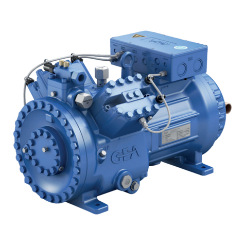
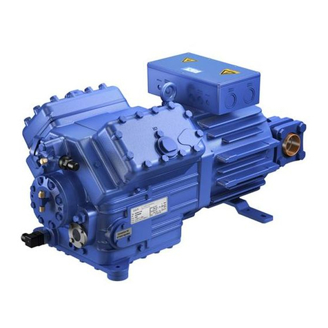
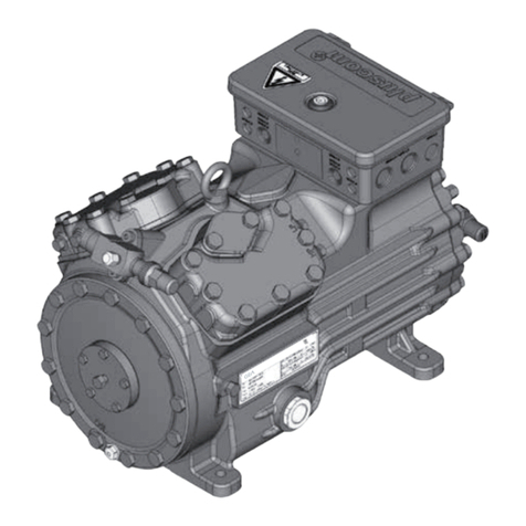
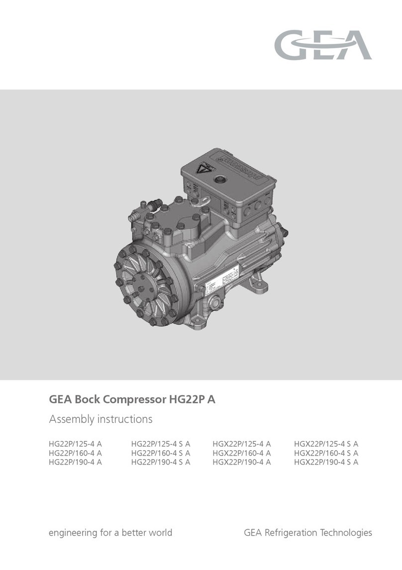
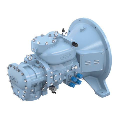
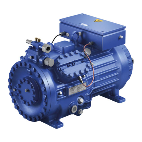
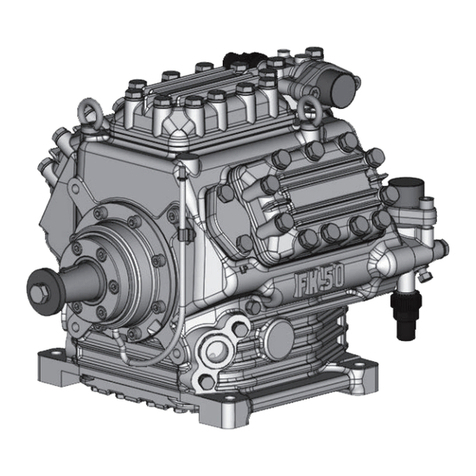
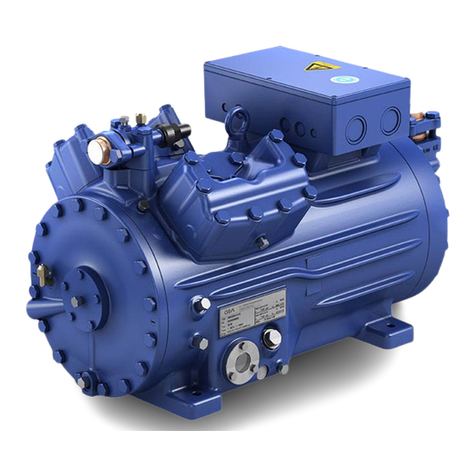
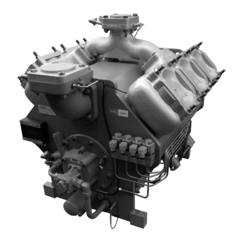
GEA Grasso RC9 Series User manual

RC9
Instruction Manual For Refrigeration Compressors
00.89.221 v003.99.06.en

Refrigeration Division
rasso
All rights reserved. No part of this publication may be copied or published by means of printing,
photocopying, microfilm or otherwise without prior written consent of rasso. This restriction also
applies to the corresponding drawings and diagrams.
For extra information as to adjustments, maintenance and repair, contact the Technical Department of
your supplier.
This publication has been written with great care. owever, rasso cannot be held responsible, neither
for any errors occurring in this publication nor for their consequences.
Refrigeration Compressors Series RC9 v003.99.06.en

SUBJECT ................................................................................................................................................ See page:
1. INTRODUCTION .............................................................................................................................. 1.1
2. FUNCTION OF THE COMPRESSOR IN THE REFRI ERATIN PLANT........................................... 2.1
3. TECHNICAL DATA
3.1 General technical data.............................................................................................................. 3.1
3.2 Connections and required free space ...................................................................................... 3.2
3.3 Lubrication data........................................................................................................................ 3.4
4. ENERAL DESCRIPTION OF THE COMPRESSOR
4.1 Compressor housing ................................................................................................................. 4.1
4.2 Cylinders and moving parts...................................................................................................... 4.1
4.3 Rotary shaft seal ....................................................................................................................... 4.2
4.4 Suction and discharge valves.................................................................................................... 4.2
4.5 Valve-lifting mechanism............................................................................................................ 4.3
4.6 Cylinder head cooling ............................................................................................................... 4.3
4.7 Principal connections and suction gas strainer........................................................................ 4.3
4.8 Pressure equalizing line and overflow safety valves ............................................................... 4.3
4.9 Oil pump, filters and control oil system................................................................................... 4.4
4.10 Lubrication system .................................................................................................................. 4.5
5. DESCRIPTION AND OPERATION OF ACCESSORIES
5.1 Pressure gauges ........................................................................................................................ 5.1
5.2 Pressure safety switches ........................................................................................................... 5.1
5.3 Crankcase heating..................................................................................................................... 5.2
5.4 Cylinder head temperature safety device................................................................................ 5.2
5.5 Capacity control
5.5.1 Manually operated capacity control............................................................................... 5.3
5.5.2 Electrically operated capacity control............................................................................. 5.5
5.6 Injection interstage gas cooler ................................................................................................. 5.5
6. OPERATION OF THE COMPRESSOR
6.1 Unloaded starting ..................................................................................................................... 6.1
6.2 Loaded operation of the compressor...................................................................................... 6.1
6.3 Liquid hammer .......................................................................................................................... 6.1
7. STARTIN , STOPPIN AND ADJUSTMENT OF COMPRESSOR
7.1 Starting the compressor ........................................................................................................... 7.1
7.2 Stopping the compressor ......................................................................................................... 7.1
7.3 Setting of the oil pressure regulator........................................................................................ 7.1
7.4 Setting of pressure safety switches.......................................................................................... 7.3
8. PERIODICAL INSPECTIONS OF THE OPERATIN COMPRESSOR
8.1 Survey of periodical inspections (Check list)............................................................................ 8.1
8.2 Explanation to the survey of periodical inspections ............................................................... 8.2
9. COMPRESSOR MAINTENANCE
9.1 Maintenance schedule.............................................................................................................. 9.1
9.2 Lubrication data........................................................................................................................ 9.1
9.3 Topping up oil with compressor operating............................................................................. 9.1
9.4 Evacuation of compressor ........................................................................................................ 9.2
9.5 Draining and change of oil....................................................................................................... 9.2
9.6 Cleaning of oil filters................................................................................................................. 9.2
9.7 Cleaning of the suction gas strainer ........................................................................................9.3
9.8 Dismounting, inspection and reassembly of suction and discharge valves ........................... 9.3
9.9 Compressor purging ................................................................................................................. 9.5
10. FAULT FINDIN TABLE................................................................................................................. 10.1 & ff
Appendix: STANDARD ILLUSTRATED PARTS LIST........................................................................... 1 - 23
Refrigeration Division
rasso
TABLE OF CONTENTS
v002.97.10.en Refrigeration Compressors Series RC9 Page I
Refrigeration Division
rasso
TABLE OF CONTENTS
Page II Refrigeration Compressors Series RC9 v002.97.10.en

This instruction manual is intended as a guide for
the operating staff in charge of the preventive
maintenance of the compressor. In addition to
data concerning the construction and operation
of the machine, the manual contains operating,
inspection and maintenance instructions which
should necessarily be followed in order to keep
the compressor in the proper state under normal
working conditions.
owever, the working conditions of a compressor
largely depend on the type and construction of
the plant of which it forms part. Consequently this
instruction manual can only be regarded as a
guide; it is important that the instructions given by
the installation engineer are observed as well.
Only then can a prolonged and trouble-free
operation of the compressor be guaranteed.
The maintenance instructions are limited to those
operations which can be performed by the
operating staff and for which no specialist
knowledge is needed. Any parts to be replaced
can be ordered on the basis of drawings with
parts lists.
For more specialized repair and overhaul
operations, the installation engineer should be
consulted.
Faults and defects of the refrigeration compressor
should be remedied as soon as possible by
qualified personnel in order to reduce down-time
to a minimum and to prevent damage to the
compressor. The fault-finding table (Chapter 10)
may be used to trace and remedy faults quickly.
It is finally pointed out that in individual cases the
construction of the compressor may differ from
the normal design, in which event the instruction
may no more be applicable at certain specific
points. In such cases it is advisable to consult the
plant manual or contact the installation engineer.
The plant manual referred to above and in other
sections of this instruction manual should be
supplied by the contractor/installer.
Refrigeration Division
rasso
1. INTRODUCTION
v002.97.10.en Refrigeration Compressors Series RC9 Page 1.1

Refrigeration Division
rasso
1. INTRODUCTION
Page 1.2 Refrigeration Compressors Series RC9 v002.97.10.en

A refrigerating plant is used in cases where a certain
room or certain materials are to be brought up to or
be maintained at a temperature lower than the
ambient temperature. This low temperature is
brought about by the evaporator of the
refrigerating system. In it a liquid refrigerant
evaporates due to its being maintained artificially at
low pressure; the heat required for this evaporation
is withdrawn from the surrounding atmosphere.
The function of the compressor consists in
maintaining this low pressure in the evaporator
and this by continuously sucking the vapour thus
formed from the evaporator. Therefore the name
“suction pump” would have been more
appropriate for this machine. It derives its present
name from the fact that it compresses the sucked
vapour, which thus reaches a high pressure,
thereby strongly increasing in temperature.
owever, this high pressure also involves a higher
temperature at which the vapour passes into
liquid. This temperature is above the ambient
temperature; hence it is possible for the
compressed vapour to be condensed on an air or
water cooled surface.
This process takes place in the condenser. The
liquid thus formed is fed from the condenser to
the evaporator again in order to evaporate there
anew. In the line between the two apparatuses, a
liquid regulator is fitted, which ensures that the
right amount of refrigerant flows to the
evaporator and maintains the pressure difference
between condenser and evaporator.
The correct operation of the compressor highly
depends on the rest of the plant. If, for example,
the installation contains too many impurities, the
compressor may get out of order; also, when the
plant itself has been dimensioned, assembled or
installed incorrectly, the result may be
malfunctioning of or damage to the compressor.
In the event of compressor failure, it is therefore
mostly necessary also to seek the causes in the
other elements of the plant or in a shortage or
excess of refrigerant charge.
In general it is essential, therefore, to have on
hand an operating manual of the plant. Only then
will it be possible to report in time any deviations
from the normal operating conditions of the plant
and take prompt action before serious
breakdowns occur.
Refrigeration Division
rasso
2. FUNCTION OF THE COMPRESSOR
IN THE REFRI ERATION PLANT
v002.97.10.en Refrigeration Compressors Series RC9 Page 2.1

Refrigeration Division
rasso
2. FUNCTION OF THE COMPRESSOR
IN THE REFRI ERATION PLANT
Page 2.2 Refrigeration Compressors Series RC9 v002.97.10.en

The range of RC9 refrigeration compressors includes 3-single-stage and 2 two-stage compressor types. All
these types are suitable for the usual refrigerants. The single-stage compressors can also used as booster.
3.1 ENERAL TECHNICAL DATA
Cylinder bore
Piston stroke
Rotational speed
Suction pressure (on pressure gauge)
Max. discharge pressure (on pressure gauge)
Max. allowable difference between suction and discharge pres-
sure
Max. discharge temperature
Max. oil temperature (measured on suction line to oil suction
filter)
Direction of rotation
min.
max.
min.
max.
max.
max.
max.
max.
mm
mm
rev/min
rev/min
bar(e)
bar(e)
bar(e)
bar
°C
°C
110
85
600
1450
-0.7
6.0
21.0
17.5
170
70
normally counter-
clockwise (faced
against shaft end)
REMARK: bar(e) means gauge pressure
Single-stage compressors Two-stage compressors
Compressor type RC29 RC49 RC69 RC219* RC429
Number of cylinders
Weight, without flywheel and
accessories
Oil charge** in crankcase
LP
P
kg
dm3
2
–
270
3.5
4
–
370
4
6
–
545
8
2
1
370
4
4
2
545
8
*In principle as RC49, less one cylinder, valve assembly, piston and connecting rod.
**For further lubrication data, refer to Chapter 3 and 9 and to lubrication oil table 3.1.
Refrigeration Division
rasso
3. TECHNICAL DATA
v002.97.10.en Refrigeration Compressors Series RC9 Page 3.1

All dimensions in mm
Refrigeration Division
rasso
3. TECHNICAL DATA
Page 3.2 Refrigeration Compressors Series RC9 v002.97.10.en

All dimensions in mm
COMPRESSOR
TYPE
MAIN CONNECTIONS
hole dia. in counter flange in mm
OTHER CONNECTIONS
for all types
1 2 3 4 5 Suction pressure
6 Crankcase pressure
7 Discharge pressure connection
(single- stage) or interstage pressure
connection (two-stage)
8 Discharge pressure connection
(two-stage)
9 Oil pressure
10 Return oil separator
11 Oil temperature
12 Oil charge and drain valve
13 Cooling water supply
14 Crankcase heating
15 Oil leakage drain of rotary
shaft seal
clamp coupling for
6 x 1 mm steel
precision tube
1/2" BSP female
(plugged off)
1/2" BSP male
1/2" BSP female
with steel precision
tube 12 x 1.5 mm
SIN LE
STA E
RC29
RC49
RC69
ø55 1)
ø55 2)
ø91
ø43
ø62
ø77
–
–
–
–
–
–
TWO-
STA E
RC219
RC429
ø55 1)
ø77
ø43
ø62
ø43
ø62
ø43
ø43
1) O.D. of suction line: ø62 mm
2) O.D. of suction line: ø77 mm
Refrigeration Division
rasso
3. TECHNICAL DATA
v002.97.10.en Refrigeration Compressors Series RC9 Page 3.3

All compressors are provided with an oil pump. The
crankcase oil level must reach about the middle of the
sight glass. The amount of oil charge is shown in table
3.1.
The lubrication pressure (i.e. the difference between
the oil pressure, measured at the end of the
lubricating circuit and the suction pressure) at
operating temperature is pre-set at a value of 1.5 bar.
The maximum permissable oil temperature is 70 °C,
which best can be measured at the suction line to the
oil suction filter with a contact thermometer.
The compressor should not be started with an oil
temperature below 40 °C.
OIL TYPES
For lubrication of refrigeration compressors, several
brands and types of specially developed lubricating
oils are on the market. The choice of oil depends not
only on its good lubrication properties (viscosity) and
chemical stability at the operating conditions of the
compressor, but also on kind and operating
conditions of the refrigerating plant (solidifying and
floc point, solvability). As far as the lubrication
properties are concerned, Grasso has tested and
approved for use in RC9- compressors the brands and
types of oil as listed in the table on page 3.4. Some of
the oil types listed in the table may be marketed
under other names and/or designations; these oils
can also be used, provided their identity can be
proved beyond any doubt.
Application of other oils is not permitted without
written consent of Grasso.
The choice of the viscosity of the lubricating oils
depends on the operating conditions of the
compressor. In general, a viscosity of 4 to 4.5 E at 50
°C will satisfy.
owever, a higher viscosity should be chosen when a
high oil temperature is expected, due to arduous
operating conditions, such as:
•a high ambient temperature of the compressor
(high engine room temperature)
•a more than normal superheat of the refrigerant
suction vapour;
•prolonged part load operation with a large num-
ber of cylinders cut out
For less arduous operating conditions a lower viscosity
may be used. For strongly varying conditions (e.g. in
summer & winter), a viscosity of 4.5 E is recommended.
To ensure proper lubrication of the compressor moving
parts, the actual oil viscosity under all operating
conditions should never be less than 10 to 15 cSt
(= 1.85 to 2.35 °E).
IMPORTANT REMARK!
All viscosities mentioned relate to pure oil only and it
should be kept in mind that the actual viscosity in the
crankcase o an operating compressor, which is decisive
or the lubrication, is always lower due to dilution by
dissolved re rigerant. The magnitude o the viscosity
decrease is not only determined by the type o oil and
re rigerant, but also and essentially by the pressure and
temperature prevailing in the crankcase.
Table 3.1 Oil to be used for lubrication
TYPE
VISCOSITY
BRAND at 40 oCat 50
oC
cSt mPa.s oEngler
BP Energol LPT-F46
* Energol LPT-F 68
54
68
29
36
4.4
5.5
ESSO
* Zerice 46
* Zerice 68
* Zerice S 46
43
63
48
25
34
27
3.8
5.0
4.1
FINA Purfrigol MP 68 54 29 4.4
KUWAIT Stravinsky C 55 29 4.4
MOBILOIL Gargoyle Arctic 300 55 30 4.6
S ELL
* Clavus Oil G 46
* Clavus Oil G 68
* Clavus Oil 46
* Clavus Oil 68
46
68
46
68
26
35
26
35
3.9
5.4
3.9
5.4
TEXACO Capella WF 68 61 31 4.7
SUN-OIL Suniso 4 GS 1)
Suniso 5 GS
54
95
29
48
4.4
7.1
Oil types marked with an asterisk (*) have a viscosity grade number designation according to ISO Standard 3448.
Refrigeration Division
rasso
3. TECHNICAL DATA
Page 3.4 Refrigeration Compressors Series RC9 v002.97.10.en

4.1 COMPRESSOR HOUSIN (see fig. 4.1)
The compressor housing is of a welded steel
construction and comprises both the crankcase
and the cylinder jacket(s). In the bottom part of
each cylinder jacket, two interchangeable cylinder
liners are provided, pressed into two supporting
rings welded onto the jacket. The space between
cylinders liner and jacket serves as suction
chamber. The discharge chamber is formed by the
upper part of the cylinder jacket shut-off by the
cylinder head cover.
The crankshaft runs in bearing covers shutting off
both sides of the crankcase and on which also the
oil pump and the rotary shaft seal housing are
fitted. The oil required for compressor lubrication
FIG. 4.1 CONSTRUCTION OF THE COMPRESSOR
1. Crankcase
2. Cylinder jacket
3. Suction manifold
4. Discharge manifold
5. Cylinder liner with valve-lifting mechanism
6. Cylinder head cover
7. Cooling water jacket
8. Bearing cover
9. Oil pump
10. Rotary shaft seal
11. Oil sight glass
12. Sleeve for heating element
13. Non-return valve
14. Service cover
15. Piston
16. Connecting rod
17. Crankshaft
18. Thrust bearing
19. Cast-on counterweight
20. Suction connection
21. Discharge connection
22. Gas suction strainer
23. Oil discharge filter
24. Oil suction filter
25. Oil charge and drain valve
26. Valve lifting control piston
27. Suction and discharge valve assembly
28. Buffer spring
29. Crankcase pressure equalizing line
Refrigeration Division
rasso
4. ENERAL DESCRIPTION THE COMPRESSOR
v002.97.10.en Refrigeration Compressors Series RC9 Page 4.1

is at the bottom of the crankcase. To determine
the oil level, a sight glass is located on the
crankcase. To heat the oil, if necessary, all
compressors have a sleeve welded on to the
crankcase bottom, into which a heating element
(available as an accessory) can be inserted.
The oil which is separated in the suction chamber
from the refrigerant vapour can flow back to the
crankcase via a non-return valve. This valve is
fitted between suction chamber and crankcase in
the lower supporting ring of the cylinder liners
(except in the P-cylinders in two-stage
compressors). The valve, normally open, closes
when the crankcase pressure exceeds the suction
pressure.
The crankcase interior is accessible via one or two
service covers provided on both sides of the
crankcase.
4.2 CYLINDERS AND MOVIN PARTS (see fig. 4.1)
The cylinders are formed by interchangeable
cylinder liners pressed into the supporting rings in
the cylinder jackets. The collar on top of the
cylinder liners is provided with openings and acts
as a seat for the suction valve ring. In the cylinder
liners, light metal pistons are located, on which
three compression rings and one oil scraper ring
are fitted.
The connecting rods have a split-type big end, in
which white metal lined steel precision bearing
shells are positioned. To provide bearing for the
gudgeon pin, a bronze bush or, in the case of
P-cylinders of two stage compressors, a needle
bearing is pressed into the small end.
The crankshaft is mounted in slide bearings
consisting of interchangeable white metal lined
steel bushes pressed into the bearing covers. The
crankshaft, furnished with cast-on counterweights,
is dynamically balanced. The tapered shaft end
with key for taking up flywheel or coupling, is
carried gastight through the bearing cover (see
par. 4.3, Rotary shaft seal).
4.3 ROTARY SHAFT SEAL
In order to pass the crankshaft (2) gastight
outwards, the compressor is provided with a
special rotary shaft seal, the construction of which
is shown in fig. 4.2.
The sealing between rotating and stationary parts
is effected on the sliding surface between a
carbon slip ring (7.1) rotating with the crankshaft
and a stationary counterslip ring (6) fitted in the
shaft seal housing (4). For this purpose the sliding
surface of both slip rings is ground to extreme
finish and lapped.
The carbon slip ring is carried by the slip ring
holder and forms an integral part of the rotary
seal assembly (7). This assembly consists of the
afore mentioned slip ring holder with carbon
insert, a metal bellows (7.2) and a drive collar
(7.3). The drive collar in turn is locked on the
FIG. 4.2 ROTARY SHAFT SEAL
1. Bearing cover
2. Drive pin
3. Rotary shaft seal assembly:
3a. Drive collar
3b. Metal bellows
3c. Slip ring holder with
carbon insert
4. O-ring
5. Grub screw
6. Shaft seal housing
7. Stationary counter-slip ring
8. Crankshaft
A Oil supply from internal
lubricating circuit
B Oil to oil pressure regulator
C Oil leakage drain of rotary
shaft seal
Refrigeration Division
rasso
4. ENERAL DESCRIPTION THE COMPRESSOR
Page 4.2 Refrigeration Compressors Series RC9 v002.97.10.en

crankshaft by means of three grub screws (7.4)
and a drive pin (3) . The slip ring holder with
carbon insert can slide axially over the crankshaft
and is pressed on to the counter-slip ring by
means of the metal bellows.
O-rings (5 and 7.5) are provided to ensure the
sealing between rotary seal assembly and
crankshaft and between counter-slip ring and
shaft seal housing.
To remove sufficiently the frictional heat
developed by the slip rings, the shaft seal is
incorporated in the lubricating oil circuit (see
further Paragraph 4.10, “Lubrication system”).
4.4 SUCTION AND DISCHAR E VALVES
(see fig. 4.3)
The suction and discharge valves of the
compressor are of the ring type. They contain
steel valve rings pressed, under spring tension, on
to a seat and shutting off the openings provided
in it. The lift of the valve rings is limited by a
stroke limitor. The suction valve only has one valve
ring retained, together with one sinusoidal spring,
between the valve seat type collar of the cylinder
liner and a stroke limitor.
The stroke limitor of the suction valve is centred
by the collar of the cylinder liner.
The discharge valve consists of a valve seat and a
stroke limitor, fixed together by means of bolts,
and between which the one valve ring, together
with four sinusoidal springs is placed
concentrically. The discharge valve seat and the
suction valve stroke limitor are one and the same.
The whole assembly is pressed on to the collar of
the cylinder liner by a powerful buffer spring. For
the function of this buffer spring, see Chapter 6,
par. 6.3, Liquid ammer.
Fig. 4.3 only shows schematically the construction
and operation of the suction and discharge valves.
For the real construction, reference is made to
Chapter 9, Compressor Maintenance.
4.5 VALVE LIFTIN MECHANISM (see fig. 4.4)
In order to enable the compressor to start
unloaded, all cylinders have be put out of action
mechanically by suction valve ring lifting during
compressor standstill. For this purpose a lifting
bush is provided in each cylinder, which can move
up and down around the cylinder liner. The lifting
bush is provided at the top with push pins capable
of lifting the suction valve ring from its seat via
openings in the collar of the cylinder liner. The
lifting bush is connected with an oil pressure
controlled spring-loaded piston, located in a
housing on the outside of the cylinder jacket, by
means of a lever. The piston can be moved
upward by control oil pressure from the oil pump.
At compressor standstill there is no oil pressure,
the piston is forced down by the spring causing
the lifting bush with push pins to move upwards
FIG. 4.3 SCHEMATIC CONSTRUCTION AND OPERATION OF SUCTION AND DISCHARGE VALVE
1. Buffer spring
2. Spring cup, also discharge
valve stroke limitor
3. Discharge valve ring
with sinusoidal springs
4. Suction valve stroke limitor,
also discharge valve seat
5. Suction valve ring
with sinusoidal springs
6. Cylinder liner, also
suction valve seat
A Discharge
B Suction
Refrigeration Division
rasso
4. ENERAL DESCRIPTION THE COMPRESSOR
v002.97.10.en Refrigeration Compressors Series RC9 Page 4.3

and lift the suction valve ring. Shortly after the
compressor has been started, control oil pressure
is admitted to the piston and moves it upward, so
that the lever tilts, thus pulling the lifting bush
with the push pins downwards while the suction
valve ring descents onto its seat. After completion
of the latter movement, the cylinder is in
operation.
4.6 CYLINDER HEAD COOLIN
All cylinder heads on the compressor are provided
with a cooling water jacket and blanked off water
in- and outlet connections.
Only in cases where extremely high cylinder head
temperatures occur, will this possibility of cylinder
head cooling be used by the installation engineer.
In these cases reference is made to the details
given in the plant manual.
4.7 PRINCIPAL CONNECTIONS AND SUCTION
AS STRAINER
The suction and discharge chambers of the
cylinders open, via one or more lines, into a single
suction and discharge connection with flange,
with which the compressor is coupled to the
refrigerating plant via stop valves. The (LP)-suction
connection is fitted on the suction strainer
housing, in which a removable metal strainer
element is provided for purifying the intake
refrigerant gas. Compressor type RC69 is provided
with two strainer elements.
In the case of two-stage compressors, the
LP-discharge connection is connected, via an
interstage cooler, to the P-suction connection
(see also Chapter 5, par. 5.6, Injection interstage
gas cooler). Compressor type RC429 includes
already a built-in P-suction strainer.
All principal connections have nipples for
connecting pressure gauges or pressure safety
switches.
4.8 PRESSURE EQUALIZIN LINE AND
OVERFLOW SAFETY VALVES
Between suction strainer housing and crankcase
an equalizing line is provided in order to prevent
the crankcase pressure* from rising due to piston
leakage. Moreover, the crankcase can thus be
evacuated for charging lubricating oil or for
venting the compressor.
FIG. 4.4 VALVE—LIFTING MECHANISM
1. Lever
2. Piston housing
3. Spring
4. Control piston
5. Suction valve ring
6. Push pin
7. Lifting bush
A Control oil pressure
Refrigeration Division
rasso
4. ENERAL DESCRIPTION THE COMPRESSOR
Page 4.4 Refrigeration Compressors Series RC9 v002.97.10.en

Crankcase pressure = suction pressure for both
single- and two-stage compressors
In order to prevent excessive discharge pressures
in the compressor, one or more overflow safety
valves (number depends on the type of
compressor) are provided. These valves act on the
difference between suction and discharge
pressure and moreover, in the case of two-stage
compressors, between suction and intermediate
pressure.
The spring-loaded overflow safety valves are
adjusted at the works; they blow the gas off to
suction when there is an excessive pressure
difference.
The overflow safety valves are fitted externally
between the suction manifold and the P and/or
LP discharge manifold.
4.9 OIL PUMP, FILTERS AND CONTROL OIL
SYSTEM (see fig. 4.5)
The oil pump is fitted on the bearing cover
opposite the compressor driving end and is
directly driven by the crankshaft.
The pump housing accomodates a double gear
pump consisting of three gears with the centre
gear driven by the crankshaft.
The oil suction and oil discharge filters are fitted
to the pump. The oil suction filter contains a metal
gauze filter element; the oil discharge filter is
provided with a paper filter element retaining the
fine (metal) particles suspended in the oil.
The oil is drawn from the crankcase via the oil
suction filter. The pressures dilevered by the gear
pump are a lubricating pressure and a control
pressure to operate the valvelifting mechanisms
(capacity control). The pressurized lubricating oil is
delivered to the discharge filter, led back to the
pump housing and into the lubricating system via
the crankshaft. The lubricating oil pressure
depends on the setting of the lubricating oil
pressure regulator built into the lubrication system
of the compressor (see also par. 4.10, Lubrication
system). The control oil pressure delivered by the
pump is regulated by a built-in relief valve
connected to the lubrication system. Excess of
control oil is thus used for lubrication. The control
pressure has been set at 13 - 15 bar above suction
pressure.
FIG. 4.5 OIL PUMP, FILTERS AND CONTROL OIL SYSTEM
1. Oil suction filter
2. Oil discharge filter
3. Relief valve
4. Gear pump
5. ydraulic time delay
valve
A To lubrication system via crankshaft
B Control oil pressure to valve lifting mechanisms
for unloaded starting and capacity control
C Oil suction from crankcase
Refrigeration Division
rasso
4. ENERAL DESCRIPTION THE COMPRESSOR
v002.97.10.en Refrigeration Compressors Series RC9 Page 4.5

After starting the compressor, the through-flow of
the control oil pressure to the valve lifting
mechanisms is interrupted for 30 to 60 seconds by
a hydraulic delay valve provided in the pump. This
valve consists of a plunger and a spring-loaded
piston. During compressor standstill the piston,
due to the spring tension, is in its extreme
position, as a result of which the plunger shuts off
the through-flow of oil. The space behind the
piston is filled with oil. As soon as the compressor
is operated, plunger and piston will be forced
down by the pump pressure, but encounter
resistance of the oil behind the piston. This oil
should first leak away along the piston before the
plunger can clear the through-flow.
The delay time depends on the viscosity and
consequently on the oil temperature. As soon as
the compressor has stopped, it may not be
restarted until after 3 minutes in order to prevent
the compressor from starting on load. During this
period the delay valve is returned by the spring to
its original position. A check valve in the piston
ensures that the space behind the piston is filled
again with oil.
4.10 LUBRICATION SYSTEM
The lubrication of the compressor is effected
under pressure; the lubricating oil circuit is shown
in fig. 4.6, overleaf
The pump draws the oil from the crankcase via a
suction filter and feeds it back under pressure to
the oil pump housing via a discharge filter.
From this housing the oil flows into the
crankshaft, in which a continuous oil channel is
drilled, provided with radially drilled oilways in situ
of the bearings. The connecting rods also have an
internal oil channel through which the oil is
supplied to the small end bearings. Sufficient
lubrication of the cylinder walls is ensured by the
oil that is forced out of the bearings and splashed
around. The oil channel in the crankshaft ends in
the shaft seal housing.
As, besides its lubricating function, the oil also has
a cooling function, especially for the rotary shaft
seal, the amount of circulating oil is considerably
more than that required for lubricaton. This excess
of oil is led back, via an external line to the pump
FIG. 4.6 LUBRICATION SYSTEM
A External oil return line
B Shaft seal housing
C Oil channel in crankshaft
D Lubricating oil pressure regulator
E Oil pump
F Sight glass
Oil suction filter
H Oil discharge filter
Refrigeration Division
rasso
4. ENERAL DESCRIPTION THE COMPRESSOR
Page 4.6 Refrigeration Compressors Series RC9 v002.97.10.en

end of the crankcase, from where it flows back to
the oil sump via an internal line: this oil stream is
visible behind the sight glass. In the return line an
adjustable lubricating pressure regulator is fitted.
This spring-loaded ball valve allows the return oil
to pass at a certain pressure only, thus
determining the pressure in the lubrication system.
The connection for the oil pressure gauge and the
lubricating oil pressure safety switch is provided
upstream the pressure regulator on the shaft seal
housing.
The oil pump supplies, besides the lubricating oil
pressure, also a separate control oil pressure for
the valve lifting mechanism; for further data refer
to chapter 4.9. Oil pump, filters and control oil
system.
Refrigeration Division
rasso
4. ENERAL DESCRIPTION THE COMPRESSOR
v002.97.10.en Refrigeration Compressors Series RC9 Page 4.7

Refrigeration Division
rasso
4. ENERAL DESCRIPTION THE COMPRESSOR
Page 4.8 Refrigeration Compressors Series RC9 v002.97.10.en
This manual suits for next models
5
Table of contents
Other GEA Air Compressor manuals

GEA
GEA pluscom Bock EX-HG12P User manual

GEA
GEA HGX4 R134a User manual

GEA
GEA HG6/1080-4 User manual

GEA
GEA GEA Bock HG66e Series User manual

GEA
GEA HG22P Series User manual

GEA
GEA FK40/560 N User manual

GEA
GEA HG76e/1620-4 User manual

GEA
GEA FK50/460 N User manual

GEA
GEA HG34P/e User manual

GEA
GEA Bock HGZ Series User manual

GEA
GEA HA4 User manual

GEA
GEA HG4 User manual

GEA
GEA Bock HG8 Series User manual

GEA
GEA F Series User manual

GEA
GEA HGX22P CO2 Series User manual

GEA
GEA HG88e series User manual

GEA
GEA Grasso M-Series User manual

GEA
GEA HGX34/110-4 ML CO2 T User manual

GEA
GEA HG22e/125-4 User manual

GEA
GEA HG4/310-4 User manual