manuals.online logo
Brands
  1. Home
  2. •
  3. Brands
  4. •
  5. Gecko
  6. •
  7. Control Unit
  8. •
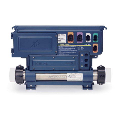
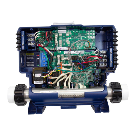
  9. Gecko in.xe-5 0602-221063-299 Technical manual

Gecko in.xe-5 0602-221063-299 Technical manual

2- Connect the main power
Don't forget that the voltage is determined by the cable used (120 or 240 V cable)!
1- Connect all outputs & keypads
OUT1 OUT2 OUT3 OUT4
3- Select spa configuration (see chart next page)
3
At first startup the keypad display
will showõL 1 ORLL 1.
Use the Up/Down key to choose the
new low level configuration number.
Press the Program key to confirm the
selection.
21
L1 - Light connector
CO - Communication link
C - Main keypad connector
OUT5
Ground GroundL2 NL1 L1
Ground
L2
L1
For 120 V (*3 wires)
* If connected to a 3 wire system all
240 V components will not work.
The heat.wav heater is factory configured 240 V/4 kW (or 2 kW), but it can
be converted to a dedicated 120 V / 1 kW by a simply switching the cable
connection port. Option available on North American models only.
Heat.wav specification summary:
t4VQQPSUT7PS7t1SPUFDUFECZFYUFSOBMCSFBLFSOPUGVTFEt*ODPMPZ®or Titanium (optional) heater element for greater protection
against corrosion.
Connection for 240 V / heater (4 kW) Connection for 120 V / heater (1 kW)
Gro
und
N
L1
For 240 V (4 wires)
WARNING! All connections must be made by a qualified electrician in accor-
dance with the national electrical code and any state, provincial or local electrical
code in effect at the time of the installation. This product must always be connec-
ted to circuit protected by a Ground Fault Circuit Interrupter (GFCI).
2.a- Electrical wiring 2.b- Heater voltage
Note: 4o re-enter the Low level
selection menu, hold the Pump 1õkey for 30 seconds.
NoteIf the keypad does not have a
ProgramõorõFilter key, use the Lightõkey instead.
Note: For the Color keypad seriesõselect Settings menu, go into
Electrical config and choose the
appropriate Low level.
For more information, see our
website: www.geckoalliance.com
GFCI b
60 A 48 A
50 A 40 A
40 A 32 A
30 A 24 A
20 A 16 A
15 A 12 A
Press and hold the Program key
for 20 seconds until you access the
breaker setting menu.
Note: For the Color keypad seriesõselect Settings menu, go into
Electrical config and choose Input
current.
Use the Up/Down key to select
the desired value. Then press the
Program key to confirm the selection.
Note: If the keypad does not have the
Program or Filter key, use the Light
key instead.
The values displayed by the system
DPSSFTQPOEUPPGUIFNBYJNVNamperage capacity of the GFCI.
4- Select breaker current

(10 to 20 A dedicated to 120 V)
321
For more information, see our
website: www.geckoalliance.com
Quick Start Card
in.xe-5™North American version
Configuration selection chart
Standard
config. # Pump 1 Pump 2 Pump 3 Pump 4 Pump 5 Blower DIRECT 1 DIRECT 2 Circ. Pump (CP)
configuration
Ozone (O3)
configuration 1
Filter cycle
daily Heater
1
2SP
(OUT1)
12A-4A ?????X
(OUT5)
1A ??On filter cycle
(OUT4)
0A
2 * 2 hour
with P1 with P1
17A
2
2SP
(OUT1)
12A-4A ?????X
(OUT5)
1A ?On filter cycle
(OUT3)
2A
On filter cycle
(OUT4)
0A
2 * 6 hour
with CP with CP
17A
3
2SP
(OUT1)
12A-4A
1SP
(OUT2)
10A ????X
(OUT5)
1A ??On filter cycle
(OUT4)
0A
2 * 2 hour
with P1 with P1
17A
4
2SP
(OUT1)
12A-4A
1SP
(OUT2)
10A ????X
(OUT5)
1A ?On filter cycle
(OUT3)
2A
On filter cycle
(OUT4)
0A
2 * 6 hour
with CP with CP
17A
5
2SP
(OUT1)
12A-4A ????X
(OUT3)
5A
X
(OUT5)
1A ??On filter cycle
(OUT4)
0A
2 * 2 hour
with P1 with P1
17A
6
2SP
(OUT1)
12A-4A ????X
(OUT3)
5A
X
(OUT5)
1A ?On filter cycle
(OUT4)
2A ?2 * 6 hour
with CP with CP
17A
7
2SP
(OUT1)
12A-4A
1SP
(OUT2)
10A ???X
(OUT3)
5A
X
(OUT5)
1A ??On filter cycle
(OUT4)
0A
2 * 2 hour
with P1 with P1
17A
8
2SP
(OUT1)
12A-4A
1SP
(OUT2)
10A ???X
(OUT3)
5A
X
(OUT5)
1A ?On filter cycle
/542A ?2 * 6 hour
with CP with CP
17A
9
1SP
(OUT1)
12A ?????X
(OUT5)
1A ?On filter cycle
(OUT3)
2A
On filter cycle
(OUT4)
0A
2 * 6 hour
with CP with CP
17A
10
1SP
(OUT1)
12A
1SP
(OUT2)
10A ????X
(OUT5)
1A ?On filter cycle
/542A
On filter cycle
(OUT4)
0A
2 * 6 hour
with CP with CP
17A
11
1SP
(OUT1)
12A
1SP
(OUT2)
10A ???X
(OUT3)
5A
X
(OUT5)
1A õ?On filter cycle
(OUT4)
2A ?2 * 6 hour
with CP with CP
17A
12
1SP
(OUT1)
12A
1SP
(OUT2)
10A ????X
(OUT5)
1A ??On filter cycle
(OUT4)
0A
2 * 2 hour
with P1 with P1
17A
13
1SP
(OUT1)
12A
1SP
(OUT2)
10A ???X
(OUT3)
5A
X
(OUT5)
1A ??On filter cycle
(OUT4)
0A
2 * 2 hour
with P1 with P1
17A
14
2SP
(OUT1)
12A-4A
1SP
(OUT2)
10A ???X
(OUT3)
5A
X
(OUT5)
1A ?On filter cycle
(OUT4)
2A ?2 * 6 hour
with CP with P1
17A
Swim Spa
config. #
51
2SP
Master (OUT1)
12A-4A
1SP
Master (OUT2)
10A
1SP
4MBWF06510A
1SP
4MBWF06510A ??X
Master (OUT5)
1A
X
4MBWF0651A
On filter cycle
Master (OUT3)
2A
On filter cycle
Master (OUT4)
0A
2 * 6 hour
with CP with CP
17A
52
2SP
Master (OUT1)
12A-4A
1SP
Master (OUT2)
10A
1SP
4MBWF06510A
1SP
4MBWF06510A ??X
Master (OUT5)
1A
X
4MBWF0651A ?On filter cycle
Master (OUT4)
0A
2 * 2 hour
with P1 with P1
17A
53
2SP
Master (OUT1)
12A-4A
1SP
Master (OUT2)
10A
1SP
4MBWF06510A
1SP
4MBWF06510A ?X
4MBWF0655A
X
Master (OUT5)
1A
X
4MBWF0651A
On filter cycle
Master (OUT3)
2A
On filter cycle
Master (OUT4)
0A
2 * 6 hour
with CP with CP
17A
54
2SP
Master (OUT1)
12A-4A
1SP
Master (OUT2)
10A
1SP
4MBWF06510A
1SP
4MBWF06510A ?X
4MBWF0655A
X
Master (OUT5)
1A
X
4MBWF0651A ?On filter cycle
Master (OUT4)
0A
2 * 2 hour
with P1 with P1
17A
55
2SP
Master (OUT1)
12A-4A
1SP
Master (OUT2)
10A
1SP
4MBWF06510A ???X
Master (OUT5)
1A
X
4MBWF0651A
On filter cycle
Master (OUT3)
2A
On filter cycle
Master (OUT4)
0A
2 * 6 hour
with CP with CP
17A
56
2SP
Master (OUT1)
12A-4A
1SP
Master (OUT2)
10A
1SP
4MBWF06510A ???X
Master (OUT5)
1A
X
4MBWF0651A ?On filter cycle
Master (OUT4)
0A
2 * 2 hour
with P1 with P1
17A
57
2SP
Master (OUT1)
12A-4A
1SP
Master (OUT2)
10A
1SP
4MBWF06510A ??X
4MBWF0655A
X
Master (OUT5)
1A
X
4MBWF0651A
On filter cycle
Master (OUT3)
2A
On filter cycle
Master (OUT4)
0A
2 * 6 hour
with CP with CP
17A
58
2SP
Master (OUT1)
12A-4A
1SP
Master (OUT2)
10A
1SP
4MBWF06510A ??X
4MBWF0655A
X
Master (OUT5)
1A
X
4MBWF0651A ?On filter cycle
Master (OUT4)
0A
2 * 2 hour
with P1 with P1
17A
59 2
1SP
Master (OUT2)
12A
1SP
Master (OUT1)
10A
1SP
4MBWF06510A
1SP
4MBWF06510A
1SP
4MBWF06510A
X
Master (OUT5)
1A
X
4MBWF0651A
On filter cycle
Master (OUT3)
2A
On filter cycle
Master (OUT4)
0A
2 * 6 hour
with CP with CP
17A
Software #299, rev. 002
1When the Ozonator is not controlled by a relay, it can be tied to Pump 1 Low speed or Circ. Pump.
2 4MBWF065IJHIBOEMPXTQFFEEFEJDBUFEUP1VNQBOEQVNQSFTQFDUJWFMZGlossary
P1 Pump 1
CP Circulation Pump
XInstalled
1SP High speed only
2SP High and Low speed
(OUT, AMP, Relay, Tab) Output connector
12A, 12A-4A
Output current: 1 speed or High - Low speed
9919-101314-C Rev. 11-2015
For complete TechBook or more information, see our website: www.geckoalliance.com
© Groupe Gecko Alliance Inc., 2015
All trademarks or registered trademarks are the property of their respective owners.

Other Gecko Control Unit manuals

Gecko TSPA-1 Reference guide

Gecko

Gecko TSPA-1 Reference guide

Gecko 1001 Reference guide

Gecko

Gecko 1001 Reference guide

Gecko in.yt-7 0611-221031-361 Technical manual

Gecko

Gecko in.yt-7 0611-221031-361 Technical manual

Gecko SC-CF-SBD User manual

Gecko

Gecko SC-CF-SBD User manual

Gecko IN.XE-5 0602-221046 Technical manual

Gecko

Gecko IN.XE-5 0602-221046 Technical manual

Gecko In.Touch 0608-521012 User manual

Gecko

Gecko In.Touch 0608-521012 User manual

Popular Control Unit manuals by other brands

Control Techniques FM-3 Reference manual

Control Techniques

Control Techniques FM-3 Reference manual

Lawler 61 Series Installation & maintenance manual

Lawler

Lawler 61 Series Installation & maintenance manual

Viessmann 5224 Operation manual

Viessmann

Viessmann 5224 Operation manual

TriangleTube Prestige Trimax 399 installation instructions

TriangleTube

TriangleTube Prestige Trimax 399 installation instructions

TREND XCITE/BBC Installation and mounting instructions

TREND

TREND XCITE/BBC Installation and mounting instructions

Metz Connect C6Amodul Mounting Note for the installer

Metz Connect

Metz Connect C6Amodul Mounting Note for the installer

National Instruments PXIe-4302 USER GUIDE AND SPECIFICATIONS

National Instruments

National Instruments PXIe-4302 USER GUIDE AND SPECIFICATIONS

TLV COSPECT instruction manual

TLV

TLV COSPECT instruction manual

ELCOM BEC-200 quick guide

ELCOM

ELCOM BEC-200 quick guide

Satel PK-01 manual

Satel

Satel PK-01 manual

Resol RCP12 manual

Resol

Resol RCP12 manual

Altronix MOM5 installation instructions

Altronix

Altronix MOM5 installation instructions

mikroElektronika ccRF2 click quick guide

mikroElektronika

mikroElektronika ccRF2 click quick guide

Danfoss OPTYMA user guide

Danfoss

Danfoss OPTYMA user guide

DEHACO Dust Control Unit user manual

DEHACO

DEHACO Dust Control Unit user manual

Siemens LMV 5 Series Basic documentation

Siemens

Siemens LMV 5 Series Basic documentation

Minarik SL10U user manual

Minarik

Minarik SL10U user manual

GEM 567 BioStar control operating instructions

GEM

GEM 567 BioStar control operating instructions

manuals.online logo
manuals.online logoBrands
  • About & Mission
  • Contact us
  • Privacy Policy
  • Terms and Conditions

Copyright 2025 Manuals.Online. All Rights Reserved.