Gemtor AD-1 User manual

OWNER'S MANUAL
Installation, Operating, Inspection and Maintenance Instructions
Gemtor Anchor D-Rings
Applicable Models:
AD-1
AD-1C
AD-2
GEMTOR, INC.
One Johnson Avenue
Matawan, NJ 07747
800-405-9048 • 732-583-6200
732-290-9391 (fax)
sale[email protected]m
www.gemtor.com
Warning
You must read and fully understand all instructions, or have all instructions
explained to you, before attempting to use this device. Equipment must not be
installed, operated or inspected by anyone who does not understand these
instructions. Failure to observe these instructions could result in serious injury
or death. Careless or improper use of this equipment can result in serious injury
or death. Training and instruction review should be repeated at regular intervals.
If you have any questions regarding these instructions or need additional
copies, call Gemtor, Inc. toll free at 800-405-9048
This user instruction manual is not a substitute
for a Comprehensive training program
IMPORTANT
THESE INSTRUCTIONS SHOULD BE KEPT WITH THE DEVICE AT ALL TIMES.

Page 2
GENERAL DESCRIPTION
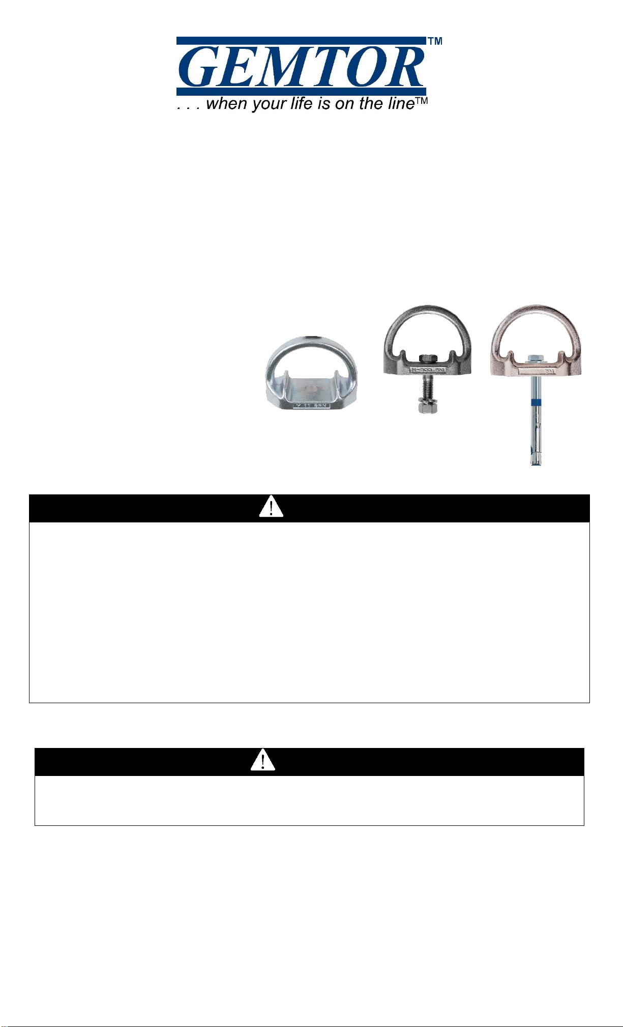
Gemtor D-Ring Anchors are designed for use where a temporary or permanent, stationary
anchorage connector is required. The Model AD-1 or AD-2 attaches quickly and easily to structures
capable of supporting at least 5000 lbs. such as the bottom or side of horizontal and vertical beams
and columns to form a rigid anchorage connector to connect a safety lanyard, retractable lifeline,
vertical and horizontal lifelines or perimeter lines for personal fall protection and fall restraint.
AVAILABLE MODELS
All models are constructed of zinc plated drop-forged alloy steel.
AD-1 –Supplied with 1/2” grade 8 bolt and nut and washer.
AD-1C –Supplied with 1/2” X 4 ¾” concrete expansion bolt.
AD-2 –Anchor without mounting hardware, provided with 1/2” mounting hole.
DAS-5KCKIT –Mounting kit for concrete. Compatible with AD-2 and DAS-5K
WARNINGS AND LIMITATIONS
•Always follow all requirements of the Occupational Safety and Health Act (OSHA) and all state
and local regulations.
•If using a snaphook for connection to the Connection Point on the D-ring anchor, always make
sure that the snaphook gate cannot contact the beam in a way that could put pressure on the
gate and cause it to open.
•Always calculate the fall distance and ensure that a clear, unobstructed distance is provided
under the beam to which the worker is attached (Remember to allow for system elongation and a
safety margin).
•Develop a rescue plan establishing what to do if a fall occurs.
•Equipment must be used by properly trained personnel only.
•The employer shall provide a training program for each employee who might be exposed to fall
hazards. The program shall enable each employee to recognize the hazards of falling and shall
train each employee in the procedures to be followed in order to minimize these hazards.[OSHA
1926.503(a)(1)]. In addition, training shall include; fall protection basics, proper use of all
applicable fall protection equipment and proper handling, maintenance and storage of the
equipment.
•Never use the D-ring anchor for anything other than its intended use.
•The suitability of this device for the intended use must be determined prior to use and is the sole
responsibility of the employer.
•Before each use, visually inspect for physical damages, wear and corrosion. Check the beam
anchor for damage, cracks, wear, corrosion, or malfunctioning parts. Inspect each system
component in accordance with its associated operation and instructions manual. If the inspection
reveals a problem or an ineffective condition, remove the unit from the service.
•A qualified person shall inspect the beam anchor at regular intervals. Units that do not pass
inspection shall be returned to Gemtor immediately for repair, satisfactory inspections should be
marked on the provided inspection log.
•Units subjected to fall arrest forces shall be immediately removed from service and not used
again until the anchor is inspected by a qualified person.
•Make sure that all system components are compatible and that potential impact forces, freefall
distances, and deceleration distances are within the allowances of applicable regulations.
•A full-body harness with attachment in the center of the wearer’s back at or above shoulder level
must be used for fall arrest.
•Use only Grade 8 or other Gemtor approved hardware.
•Ensure that the structural member and installed anchor to which the worker is attached is capable
of sustaining the fall arrest forces (5000 lbs. or twice the potential impact when designed,
installed, and used under the supervision of a qualified person).
•One worker only! Never attach more than one worker to beam anchor.
•Free fall distance shall not exceed 6 ft.
•Do not try to adjust, repair or modify any Gemtor product. For prompt service, please contact:
Gemtor, Inc., One Johnson Ave., Matawan, NJ 07747, 800-405-9048.
•Attach this device at or above the connection point on your harness whenever possible. If this
device is connected below the attachment point, you must ensure that the system is designed for
this type of attachment, can withstand the potential impact forces and can absorb a sufficient
amount of fall arrest force.
•D-ring anchor must be installed flush on surface. This may require the use of a wedge washer on
S-type (Structural I-beams) or similar structures.

Page 3
TRAINING
The employer shall provide a training program for each employee who might be exposed to fall
hazards. The program shall enable each employee to recognize the hazards of falling and shall train
each employee in the procedures to be followed in order to minimize these hazards. [OSHA
1926.503(a)(1)]
The employer shall assure that each employee has been trained, as necessary, by a competent
person qualified in the following areas:
(I) The nature of fall hazards in the work area;
(ii) The correct procedures for erecting, maintaining, disassembling, and inspecting the fall protection
systems to be used;
(iii) The use and operation of guardrail systems, personal fall arrest systems, safety net systems,
warning line systems, safety monitoring systems, controlled access zones, and other protection to be
used;
(iv) The role of each employee in the safety monitoring system when this system is used;
(v) The limitations on the use of mechanical equipment during the performance of roofing work on
low-sloped roofs;
(vi) The correct procedures for the handling and storage of equipment and materials and the erection
of overhead protection; and
(vii) The role of employees in fall protection plans;
(viii) The standards contained in this subpart. [OSHA1926.503(a)(2)]
The employer shall verify compliance with paragraph (a) of this section by preparing a written
certification record. The written certification record shall contain the name or other identity of the
employee trained, the date(s) of the training, and the signature of the person who conducted the
training or the signature of the employer. If the employer relies on training conducted by another
employer or completed prior to the effective date of this section, the certification record shall indicate
the date the employer determined the prior training was adequate rather than the date of actual
training.[OSHA 1926.503(b)(1)]
Free fall considerations
Free fall distance should be kept to a minimum,
and as required by OSHA, in no case shall
exceed 6 feet. The tie-off attachment point to the
lifeline or anchor should be located at or above
the connection point of the fall arrest equipment
on harness.
Use the diagram to calculate required clearance.
The numbers are examples, substitute the actual
distances associated with your jobsite and the
equipment being used. In the example, Minimum
Required Fall Space is 11 ft.
Minimum Required Fall Space = Free Fall +
Deceleration Distance + Length of Body +
Elongation
Swing Fall Hazard - Work directly under your
anchorage whenever possible. If a swing fall can
occur, ensure that there are no hazards in the swing
fall path. Total fall distance is greater in a swing fall
than in a vertical fall. Ensure that you account for the
added distance when calculating Minimum Required
Fall Space.

Page 4
INSTALLATION ON I-BEAM OR OTHER STRUCTURAL STEEL.
1. Locate and identify an approved compatible anchorage/structure. Be sure that the mounting
location is clean and free of debris.
2. Locate or drill a ½” diameter hole. Consideration should be given to allow sufficient clearance
to place the lock washer and tighten the nut.
3. Mount the D-Ring Anchor by passing the supplied or an approved 1/2” grade 8 bolt through
the hole in the connector and through the hole in the
structure. Attach the lock washer and nut.
4. Completely tighten to 65-75 ft.-lbs. Ensure the entire nut
is engaged on the threads, the device is securely
fastened to the structure and the head of the bolt does not
extend above shoulders of the anchor.
5. Follow all instructions pertaining to your lanyard or
lifelines correct use, especially maximum allowable
freefall, capacity, maximum deceleration distance and
maximum arresting force.
INSTALLATION IN CONCRETE
1. Use a proper drill & bit for concrete. (SDS drill/bit)
2. Drill a 1/2” (13mm) hole no less than 4.5” (114mm)
deep and 8” (203mm) away from any edge.
3. Hole must be straight & perpendicular to surface.
4. Hole must be free of debris (use compressed air)
5. Concrete strength must be at least 3000psi
(20.7MPa) and no less than 7” (178mm) thick.
6. Use the supplied or an approved 1/2” concrete
anchor only. Insert anchor in hole and tighten
to recommended torque (40ft-lbs/54Nm).
INSPECTION LOG
Model #
Date of Manufacture
Date of first use
Inspection
Date
Condition & Comments
Action
Taken
Inspector’s
Initials
AD_Ins. 3/14
Torque:
40ft-lbs
(54Nm)
No part of
fastener shall
extend beyond
this point
AD-2
DAS-5KCKIT
This manual suits for next models
2
Table of contents
Other Gemtor Safety Equipment manuals