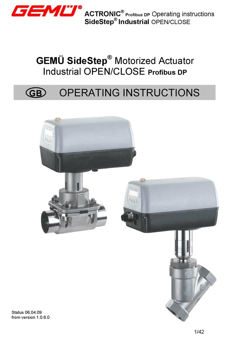
Gemu SideStep Industrial User manual

SideStep® Industrial
Stand 21. Dezember 2011 / ab Version 1.0.8.0
DE
SideStep®Motorischer Antrieb
Industrial AUF/ZU
für GEMÜ 342, 344, 538, 548, 558, 648, 9548, 9648 und 9ASS
QUICK GUIDE
Status 21 December 2011 / from version 1.0.8.0
SideStep®Motorized Actuator
Industrial OPEN/CLOSE
for GEMÜ 342, 344, 538, 548, 558, 648, 9548, 9648 and 9ASS
QUICK GUIDE
GB

2 / 28
SideStep® Industrial
Inhaltsverzeichnis
1 Hinweise zu Ihrer Sicherheit.................2
2 Mechanischer Anbau.............................2
3 Elektrische Anschlüsse.........................3
4 Ändern von Parametern........................6
5 Automatische Initialisierung................6
6 Menüstruktur..........................................8
6.1 Service..................................................8
6.2 SetBasics............................................10
6.3 SetFunction.........................................12
6.4 SetCalibration......................................14
6.5 Communication...................................16
7 Parametertabelle..................................18
1 Hinweise zu Ihrer Sicherheit
Die Sicherheitshinweise entnehmen Sie
bitte der Bedienungsanleitung des GEMÜ
SideStep®auf der beiliegenden CD-Rom.
Sollten Sie nicht im Besitz dieser CD-Rom
sein, wenden Sie sich bitte an GEMÜ.
2 Mechanischer Anbau
WARNUNG
Unter Druck stehende Armaturen!
®Gefahr von schwersten Verletzungen
oder Tod!
GNur an druckloser Anlage arbeiten.
WARNUNG
Aggressive Chemikalien!
®Verätzungen!
GMontage nur mit geeigneter
Schutzausrüstung.
VORSICHT
Heiße Anlagenteile!
®Verbrennungen!
GNur an abgekühlter Anlage
arbeiten.
VORSICHT
Ventil nicht als Trittstufe oder
Aufstiegshilfe benutzen!
®Gefahr des Abrutschens / der Beschä-
digung des Ventils.
VORSICHT
Maximal zulässigen Druck nicht
überschreiten!
®Eventuell auftretende Druckstöße
(Wasserschläge) durch Schutzmaß-
nahmen vermeiden.
VORSICHT
®Werden die Axialkräfte über die Werk-
seitig eingestellten Werte eingestellt, so
kann dies zur Zerstörung der Absperr-
dichtung führen.
Detaillierte Informationen zum mecha-
nischen Anbau entnehmen Sie bitte der se-
paraten Montageanleitung!
3 / 28 SideStep® Industrial
3 Elektrische Anschlüsse
X1
X3
X2
X4
12
34
12
34 5
1
2
3
4
5
6
12
34
Anschluss Pin Signalname
X2
M12
Dose
A-kodiert
1 Signalversorgung, 24V DC
2 Digitaleingang 1 (optional)
3 GND, Signalversorgung
4 Digitaleingang 2 (optional)
Anschluss Pin Signalname
X3
M12
Stecker
A-kodiert
1 L+, Laufrichtung AUF
2 GND, Laufrichtung AUF
3 L+, Laufrichtung ZU
4 GND, Laufrichtung ZU
5 n.c.
Anschluss Pin Signalname
X4
M12
Stecker
B-kodiert
1 n.c.
2 n.c.
3 RxD, Receive Data, RS 232
4 TxD, Transmit Data, RS 232
5 GND, RS 232
Anschluss Pin Signalname
X1
Stecker
Binder
Serie 693
1 L1/L+ Versorgungsspannung
2 N/L- Versorgungsspannung
3 Relaisausgang K1
4 Relaisausgang K1
5 Relaisausgang K2
6 Relaisausgang K2
PE PE-Schutzleiter

4 / 28
SideStep® Industrial
Contents
1 Safety instructions.................................4
2 Mechanical mounting............................4
3 Electrical connections...........................5
4 Changing parameters............................6
5 Automatic initialisation.........................6
6 Menu structure.......................................8
6.1 Service..................................................8
6.2 SetBasics............................................10
6.3 SetFunction.........................................12
6.4 SetCalibration......................................14
6.5 Communication...................................16
7 Parameter table....................................23
1 Safety instructions
For safety instructions please refer to the
GEMÜ SideStep®operating instructions on
the enclosed CD-Rom.
Please contact GEMÜ, if you do not have this
CD-Rom.
2 Mechanical mounting
WARNING
The equipment is subject to pressure!
®Risk of severe injury or death!
GOnly work on depressurized plant.
WARNING
Corrosive chemicals!
®Risk of caustic burns!
GWear appropriate protective
gear when installing.
CAUTION
Hot plant components!
®Risk of burns!
GOnly work on plant that has
cooled down.
CAUTION
Never use the valve as a step or an aid
for climbing!
®This entails the risk of slipping-offor
damaging the valve.
CAUTION
Do not exceed the maximum
permissible pressure!
®Take precautionary measures to avoid
possible pressure surges (water
hammer).
CAUTION
®If axial forces are set higher than the
factory-set values, this could result in
irreparable damage to the closing seal.
For detailed information on mechanical
mounting please refer to the separate
mounting instructions!
5 / 28 SideStep® Industrial
Connection Pin Signal name
X1
socket
Binder
series 693
1 L1/L+ Supply voltage
2 N/L- Supply voltage
3 Relay output K1
4 Relay output K1
5 Relay output K2
6 Relay output K2
PE PE-protective earth conductor
Connection Pin Signal name
X2
M12
socket
A-coded
1 Signal supply, 24V DC
2 Digital input 1 (optional)
3 GND, Signal supply
4 Digital input 2 (optional)
Connection Pin Signal name
X3
M12
plug
A-coded
1 L+, Direction of travel OPEN
2 GND, Direction of travel OPEN
3 L+, Direction of travel CLOSED
4 GND, Direction of travel CLOSED
5 n.c.
Connection Pin Signal name
X4
M12
Stecker
B-coded
1 n.c.
2 n.c.
3 RxD, Receive Data, RS 232
4 TxD, Transmit Data, RS 232
5 GND, RS 232
3 Electrical connections
X1
X3
X2
X4
12
34
12
34 5
1
2
3
4
5
6
12
34

6 / 28
SideStep® Industrial
Service
1SetBasics
2
Default: Yes
r0w3
Setup
NoInit XX.X%
Ventil kann auf- und zugefahren
werden durch Drücken der +
oder -Taste.
Einschaltmeldung nach Anlegen
der Versorgungsspannung.
automatische Initialisierung
Ohne Werksvoreinstellung.
4 Ändern von Parametern
Beim GEMÜ SideStep®werden mit
Hilfe der vier Tasten die verschiedenen
Menüs ausgewählt. Die Veränderung der
gewünschten Parameter geschieht durch
Anwählen des Parameterwertes mit der
+ Taste (1). Der Parameterwert wird
daraufhin in Klammern gesetzt (2) und kann
mit der + oder -Taste (3) verändert werden.
Beispiel:
Die Betriebsart soll von OFF auf Auto
geändert werden.
5 Automatische Initialisierung
Durch das Starten der Selbstinitialisierung
passt sich der Linearantrieb an das Ventil
an. Sämtliche Parameter werden selbständig
abgefragt.
Dieser Vorgang kann je nach Ventil ein paar
Minuten dauern.
Starten der automatischen Initialisierung
Valve can be opened and
closed by pressing the +or
-key.
automatic initialisation
Power-up message after
supply voltage is connected.
Without previous factory setting.
4 Changing parameters
The GEMÜ SideStep®has four keys which
are used to select the various menus.
To change the desired parameter, select the
parameter value using the + key (1). The
parameter value is then put in brackets (2)
and can be changed using the + oder -key
(3).
Example:
The operating mode is to be changed from
OFF to Auto.
5 Automatic initialisation
The linear actuator adapts to the valve
when automatic initialisation is started. All
parameters are automatically scanned.
This procedure can take a few minutes,
dependent on the valve.
Start the automatic initialisation
7 / 28 SideStep® Industrial
A: - 45,5 %
SETUP
Mode [ OFF]
<- OK ESC
Mode OFF
Mode [ OFF]
[ Auto]
[Manual]
<- -> + -
Mode [ Auto]
<- OK ESC
Mode Auto SETUP
(1)
(2)
(3)
goClose XX.X%
ESC
goOpen XX.X%
ESC
Init Valve
Init Valve OK
Init Valve
Auto Man ESC
r3w3
r3w3
A: - 45,5 % SETUP Mode Auto
Manual
OFF
PwrOnMode: safe SpeedAdj
R0w2 r2w2 ForceAdj
r2w2
= Selbstinitialisierung
2 x betätigen
= automatic initialisation
press twice

8 / 28
SideStep® Industrial
Diagnosis
1.3
Service
1
ID
255.255.255.255
hrs.
XXXXX:XX:XX
I / O Status
1.1 9ASS specific
1.4 Return
1.5
Code: 0
Active Level: 3
(0...10000)
Logout?
OK
NewCode:1 0
0...10000
NewCode:2 0
0...10000
Warnings ON
ON...OFF
Login
1.2
V: X.X.X.X
min - Pot - max
0,0 % 100 %
r0w3
r1w1 r1w1 r2w2
Pot Abs XX.X % Pos Ctrl Out
Error List.
r0 r0
r0 r0
w0
ActiveParaSet P1 In OPEN : CLOSE
r0 r0 r0 r0
r0
6.1 Service
6 Menüstruktur 6 Menu structure
9 / 28 SideStep® Industrial
S/N 743984/ 1
Seriennummer
serial number
Return
Relais K1 : K2
Return
Return
Return
Errors ON
ON...OFF
Clear Error List.
....
OK
NewCode:3 0
0...10000
r0w3 r0w3
r3w3
r0 TAG1
TAG1 Nummer TAG2
TAG2 Nummer
r0w3 r0w3
r0
In 1 : 2
r0

10 / 28
SideStep® Industrial
6.2 SetBasics
Return
Default Yes
Yes...No
SpeedAdj ForceAdj
r0w3 r2w2 r2w2
SetBasics
2
Helptext ON
ON...OFF
HelpLanguage D
D
GB
r0w0
r0w0
InitFOpen 5,0 %
0,0...55,0 %
StartSpOpe 20,0%
0,0...100 % StartSpClo 20,0%
0,0...100 %
r0w3 r0w3
r0w3
PwrOnMode: safe
Safe
Fast
R0w2
11 / 28 SideStep® Industrial
Init Valve
Init Valve
Auto Man ESC
D. Refresh 0.1 s
0.1...1.0 s
AutoReturn 5min
1...60min
r3w3 r0w1
DLightv On Key
On Key
On
r0w2
r0w2
Return
InitFClose 5,0 %
0,0...55,0 % ForceOpen 5,0 %
0,0...55,0 % ForceClose 5,0 %
0,0...55,0 %
Return
StopSpOpen 20,0%
0,0...100 %
Start
StopSpClos 20,0%
0,0...100 %
Start
r0w3 r0w3
r0w3 r0w3 r0w3

12 / 28
SideStep® Industrial
6.3 SetFunction
AlarmMinK2 10.0 %
0.2...99.8 %
AlarmMaxK1 10.0 %
0.2...99.8 %
AlarmMinK1 10.0 %
0.2...99.8 %
PosCtrl
SetFunction
3
Digital Output Return
Error Time 0.2 s
0.5...100 s
K1 Fn no
P min
P max
P min/max
Active
Error
Warning
CpyParaSet OFF
P1<=W
P1=>P2
P1<=P2
P1=>P3
P1<=P3
P1=>P4
AlarmMaxK2 10.0 %
0.2...99.8 %
MinPos 0.0 %
0.0...100.0 %
MaxPos 100.0 %
0.0...100.0 %
r3w3
r0w2 r0w2
r0w1
r0w1
r0w1 r0w1
r0w1
r0w3
K1 Switch NO
NO
NC
K2 Switch NO
NO
NC
r0w1 r0w1 K2 Fn no
P min
P max
P min/max
Active
Error
Warning
Return
PrefDir close
close
open
hold
r0w3 PwrFailDir ON
ON
OFF
r0w3
r0w3
r0w3 r0w3
In 1 OFF
Hold / ON
safe / ON
ParmSetB0
ParmSetB1
In 2 OFF
Hold / ON
safe / ON
ParmSetB0
ParmSetB1
Digital Input
r0w3
Return
CloseTight 5.0 %
0.0...20.0 %
r0w3 OpenTight 100.0 %
80.0...100.0 %
r0w3 TightTime 100.0 %
0.0...120.0 %
r0w3
Nur verfügbar wenn K1/K2 Func dies erfordert. Nur verfügbar wenn K1/K2 Func dies erfordert.
Only available if K1/K2 Func requires this. Only available if K1/K2 Func requires this.
13 / 28 SideStep® Industrial
Return
Error Action close
close
open
hold
r0w1 TravelTime 10 s
0...120 s
r0w3
TravelTErrFn ON
OFF /ON
r0w3 TravelLevel 1,0 %
0...100 %
r0w3

14 / 28
SideStep® Industrial
6.4 SetCalibration
SetCalibration
4
OutMinPos 0.0 %
0.0...100.0 %
OutMaxPos 100.0 %
0.0...100.0 %
r0w2 r0w2
Decimalpoint 1
0...2
Scaling
r0w3
r0w3
Scaling OFF
ON / OFF
r0w3
Return
15 / 28 SideStep® Industrial
Return
20mA = 100.0 %.
0.0...9999
4mA = 0%
0.0...9999
r0w3
r0w3

16 / 28
SideStep® Industrial
6.5 Communication
Communication
5
IR-Port
5.1
Return
WebServer
5.3
r0w3
IR-Port OFF
ON / OFF
r0w3 ComPort Auto
Auto
Serial
Analog
PC/BT
PDA/BT
Phone/BT
Fieldbus
5.2
Return
r0w3
Fieldbus OFF
ON / OFF
State
17 / 28 SideStep® Industrial
ReturnPinCode 0000
0000...9999
BT Name
SideStep
Nur verfügbar wenn ComPort: BT, Phone/BT, PDA/BT
Only available if ComPort: BT, Phone/BT, PDA/BT

18 / 28
SideStep® Industrial
Konfigebene Anzeige Funktion Wertebereich Werkseinstellung
Mode Betriebsarten wählen
AUTO
MAN
OFF
AUTO
1 Service ActiveParaSet Zeigt den momentan aktiven Parametersatz P1...P4 P1
min-Pot-max Zeigt Weggeber Stellung in Prozent
Pot Abs Stellung des Weggebers
In open : close Zeigt die momentan anliegenden
Signaleingänge
PosCtrlOut Regelabweichung zwischen Soll- und
Istwert
In 1 : 2 Zeigt die momentan anliegenden Signale
der Digitaleingänge
Relais K1:K2 Zeigt die momentane Stellung der internen
Ausgänge
Code Passwort Eingabe 0...10000 0
Logout Zugriffsperren OK
New Code: 1 Niedrigste Priorität freigeben 0...10000 0
New Code: 2 Mittlere Priorität freigeben 0...10000 0
New Code: 3 Höchste Priorität freigeben 0...10000 0
Error List Zeigt Fehlermeldungen
Warnings Warnungen im Betrieb einblenden ON / OFF ON
Errors Fehler im Betrieb einblenden ON / OFF ON
Clear Error List
Fehlerliste löschen OK
hrs. Betriebsstunden werden angezeigt
V: X.X.X.X Softwarestand wird angezeigt
ID ID-Adresse wird angezeigt
S/N Seriennummer wird angezeigt
TAG1 TAG Nr. 1 kann eingegeben werden
TAG2 TAG Nr. 2 kann eingegeben werden
4 Parametertabelle
19 / 28 SideStep® Industrial
Konfigebene Anzeige Funktion Wertebereich Werkseinstellung
2 SetBasics Default Rücksetzen auf Werkseinstellung Yes / No Yes
PwrOnMode Einschaltverhalten beim Anlegen der
Versorgungsspannung Safe / fast safe
SpeedAdj Untermenü zur Einstellung der
Geschwindigkeiten
StartSpOpe Startgeschwindigkeit Richtung AUF 0,0...100,0% 100,0%
StartSpClo Startgeschwindigkeit Richtung ZU 0,0...100,0% 100,0%
StopSpOpen Stoppgeschwindigkeit vor Erreichen
der Endlage AUF 0,0...100,0% Start
StopSpClo Stoppgeschwindigkeit vor Erreichen
der Endlage ZU 0,0...100,0% Start
ForceAdj Untermenü zur Einstellung der
maximalen Axialkräfte
InitFOpen Axialkraft Richtung AUF während der
Initialisation 0,0...55,0% 45,0%*
InitFClose Axialkraft Richtung ZU während der
Initialisation 0,0...55,0% 45,0%*
ForceOpen Axialkraft Richtung AUF 0,0...55,0% 45,0%*
ForceClose Axialkraft Richtung ZU 0,0...55,0% 45,0%*
Init Valve Starten der Initialisierung
GoClose Abfrage der geschlossenen Stellung
GoOpen Abfrage der offenen Stellung
D.Refresh Zeit für den Display Refresh 0,1...1,0s 0,1s
Dlight Einstellung der Displaybeleuchtung OnKey / On OnKey
AutoReturn Zeit für automatischen Rücksprung in
Arbeitsebene - Setup 1...60min 5min
HelpText Hilfetext einblenden ON / OFF ON
HelpLanguage Sprache der Textausgabe D / GB D
* Abhängig von Nennweite, Ventiltyp und Antriebsgröße
3 SetFunction
PosCtrl Untermenü zur Einstellung der
Stellungsregler Parameter
MinPos Schließbegrenzung = untere Position
des Regelbereichs 0...100% 0,0%
MaxPos Hubbegrenzung = obere Position des
Regelbereichs 0...100% 100%
CloseTight
Definiert den Bereich ab dem das
Ventil kraftgesteuert geschlossen
wird
0...20% 5,0%
Digital Input Untermenü zur Einstellung der
Digitaleingänge

20 / 28
SideStep® Industrial
Konfigebene Anzeige Funktion Wertebereich Werkseinstellung
3 SetFunction
In 1 Legt die Funktion des Digitaleinganges
„In 1“ fest
OFF/ON
Safe/ON
ParmSetB0
ParmSetB1
OFF
In 2 Legt die Funktion des Digitaleinganges
„In 2“ fest
OFF/ON
Safe/ON
ParmSetB0
ParmSetB1
OFF
Digital Output Untermenü zur Einstellung der Digital-
ausgänge
K1 Switch Definiert die Art des Ausgangs NC / NO NO
K1 Fn Legt die Funktion des Ausgangs K1 fest
P min
P max
P min/max
Active
Error
Warning
no
K2 Switch Definiert die Art des Ausgangs NC / NO NO
K2 Fn Legt die Funktion des Ausgangs K2 fest
P min
P max
P min/max
Active
Error
Warning
No
Error Time Legt die Zeitverzögerung zwischen
Fehlererkennung und Fehlermeldung fest 0,0...100,0 s 0,2s
ErrorAction Legt die Funktion des Prozessventils bei
Fehlermeldung fest Close/Open/Hold Close
TravelTErrFn Überwachung der Ventilbewegung ein-/
ausschalten OFF / ON ON
TravelLevel Maximale Positionsabweichung des
Ventils 0,0...100,0% 1,0%
TravelTime
Ventilstellzeit Überwachung
0,0...120,0s 10,0s
AlarmMaxK1
Schaltpunkt, der nach Überschreiten K1
schaltet
0,2...99,8% 10,0%
AlarmMinK1 Schaltpunkt, der nach Unterschreiten
K1 schaltet 0,2...99,8% 90,0%
AlarmMaxK2 Schaltpunkt, der nach Überschreiten K2
schaltet 0,2...99,8% 10,0%
AlarmMinK2 Schaltpunkt, der nach Unterschreiten
K2 schaltet 0,2...99,8% 90,0%
PrefDir Vorzugsrichtung bei Anlegen von beiden
Signaleingängen Close/Open/Hold Close
PwrFailDir Definiert die Funktion bei Ausfall der
Versorgungsspannung Close/Open/Hold Close
CpyParaSet Kopiert Parameter in unterschiedliche
Arbeitsspeicher (P1/P2/P3/P4)
21 / 28 SideStep® Industrial
Konfigebene Anzeige Funktion Wertebereich Werkseinstellung
4 SetCalibration
OutMinPos Ventilposition bei Istwertausgangs-
signal von 0/4mA 0...100% 0,0%
OutMaxPos Ventilposition bei Istwertausgangs-
signal von 20mA 0...100% 100,0%
Scaling Einschalten der skalierten Anzeige ON / OFF OFF
Decimalpoint Legt die angezeigten Nachkomma-
stellen fest 0...2 1
4mA≙Definiert die Anzeige die einem
0/4mA Signal entspricht 0%
20mA≙Definiert die Anzeige die einem
20mA Signal entspricht 100%
5
Communication
IR-Port Nicht verfügbar OFF OFF
Fieldbus Untermenü zur Einstellung der
Feldbusadresse wenn verfügbar OFF OFF
WebServer Untermenü zur Einstellung der
Kommunikationseinstellungen
ComPort Definiert die Art der
Kommunikationsverbindung
Auto
Serial
Analog
PC/BT
PDA/BT
Phone/BT
Auto
State Zeigt den aktuellen Verbindungs-
status
BT Name
Der Gerätename bei einer Blue-
toothverbindung kann eingegeben
werden
SideStep
PinCode
Der PIN Code für eine Bluetoo-
thverbindung kann eingegeben
werden
0000...9999 0000

22 / 28
SideStep® Industrial
4 Parameter table
Configuration level Display Function Value range Factory setting
Mode Select operating modes
AUTO
MAN
OFF
AUTO
1 Service ActiveParaSet Displays the current active parameter set P1...P4 P1
min-Pot-max Displays travel sensor position in percent
Pot Abs Travel sensor position
In open : close Displays the currently connected signal
inputs
PosCtrlOut Deviation between set value and actual
value
In 1 : 2 Displays the currently connected signals
of the digital inputs
Relais K1:K2 Displays the current position of the
internal outputs
Code Passwort entry 0...10000 0
Logout Block access OK
New Code: 1 Release the lowest priority 0...10000 0
New Code: 2 Release the medium priority 0...10000 0
New Code: 3 Release the top priority 0...10000 0
Error List Displays error messages
Warnings Superimpose warnings during operation ON / OFF ON
Errors Superimpose errors during operation ON / OFF ON
Clear Error List
Delete error list OK
hrs. Displays the operating hours
V: X.X.X.X Displays the software status
ID Displays the ID-address
S/N Displays the serial number
TAG1 TAG no. 1 can be entered
TAG2 TAG no. 2 can be entered
23 / 28 SideStep® Industrial
Configuration level Display Function Value range Factory setting
2 SetBasics Default Reset to factory setting Yes / No Yes
PwrOnMode Start up behaviour when the supply
voltage is connected Safe / fast safe
SpeedAdj Submenu for setting the speed
StartSpOpe Starting speed in the OPEN direction 0.0...100.0% 100.0%
StartSpClo Starting speed in the CLOSED
direction 0.0...100.0% 100.0%
StopSpOpen Stop speed before reaching the OPEN
end position 0.0...100.0% Start
StopSpClo Stop speed before reaching the CLOSED
end position 0.0...100,0% Start
ForceAdj Submenu for setting the maximum axial
forces
InitFOpen Axial force in the OPEN direction during
initialisation 0.0...55,0% 45.0%*
InitFClose Axial force in the CLOSED direction
during initialisation 0.0...55,0% 45.0%*
ForceOpen Axial force in the OPEN direction 0.0...55,0% 45.0%*
ForceClose Axial force in the CLOSED direction 0.0...55,0% 45.0%*
Init Valve Starting initialisation
GoClose Scanning the closed position
GoOpen Scanning the open position
D.Refresh Time for display refresh 0.1...1.0s 0.1s
Dlight Setting the display lighting OnKey / On OnKey
AutoReturn Time for an automatic return to the
working level - Setup 1...60min 5min
HelpText Superimposes the help text ON / OFF ON
HelpLanguage Text language D / GB D
* Depends on sizes, valve type and actuator size
3 SetFunction
PosCtrl Submenu for setting positioner parameters
MinPos Closing limit = lower position of control
range 0...100% 0.0%
MaxPos Stroke limitation = upper position of
control range 0...100% 100%
CloseTight Defines the range that the valve is closed
under controlled force 0...20% 5.0%
Digital Input Submenu for setting the digital inputs
In 1 Determines the function of the digital
input „In 1“
OFF/ON
Safe/ON
ParmSetB0
ParmSetB1
OFF

24 / 28
SideStep® Industrial
Configuration level Display Function Value range Factory setting
3 SetFunction
In 2 Determines the function of the digital
input „In 2“
OFF/ON
Safe/ON
ParmSetB0
ParmSetB1
OFF
Digital Output Submenu for setting the digital
outputs
K1 Switch Defines the type of output NC / NO NO
K1 Fn Determines the function of output K1
P min
P max
P min/max
Active
Error
Warning
no
K2 Switch Defines the type of output NC / NO NO
K2 Fn Determines the function of output K2
P min
P max
P min/max
Active
Error
Warning
No
Error Time Determines the delay time between
error recognition and error message 0.0...100.0 s 0.2s
ErrorAction
Determines the function of the
process valve if there is an error
message
Close/Open/Hold Close
TravelTErrFn Switches ON/OFF valve travel
monitoring OFF / ON ON
TravelLevel Maximum position deviation of the
valve 0.0...100.0% 1.0%
TravelTime
Valve travel time monitoring
0.0...120.0s 10.0s
AlarmMaxK1
Switch point that switches after K1 is
exceeded
0.2...99.8% 10.0%
AlarmMinK1 Switch point that switches after K1 is
undershot 0.2...99.8% 90.0%
AlarmMaxK2 Switch point that switches after K2 is
exceeded 0.2...99.8% 10.0%
AlarmMinK2 Switch ponit that switches after K2 is
undershot 0.2...99.8% 90.0%
PrefDir Preferred direction when both signal
inputs are connected Close/Open/
Hold Close
PwrFailDir Function during power failture Close/Open/Hold Close
CpyParaSet Copies parameters to various working
memories (P1/P2/P3/P4)
25 / 28 SideStep® Industrial
Configuration level Display Function Value range Factory setting
4 SetCalibration
OutMinPos Valve position at actual value output
signal 0/4mA 0...100% 0.0%
OutMaxPos Valve position at actual value output
signal 20mA 0...100% 100.0%
Scaling Switching on the scaled display ON / OFF OFF
Decimal-
point
Determines the decimal points
displayed 0...2 1
4mA≙Defines the display which corresponds
to a 0/4mA signal 0%
20mA≙Defines the display which corresponds
to a 20mA signal 100%
IR-Port Not available OFF OFF
Fieldbus Submenu for setting the fieldbus
address if available OFF OFF
WebServer Submenu for setting the communica-
tion settings
ComPort Defines the communication connec-
tion
Auto
Serial
Analog
PC/BT
PDA/BT
Phone/BT
Auto
State Displays the actual connection state
BT Name The bluetooth name can be entered SideStep
PinCode The PIN code of a bluetooth connec-
tioncan be entered 0000...9999 0000

26 / 28
SideStep® Industrial
Hinweis zur EG-Maschinenrichtlinie 2006/42/EG:
Eine Einbauerklärung gemäß EG-Maschinenrichtlinie 2006/42/EG liegt dem Produkt bei.
Beim Einbau in eine als Maschine geltende Installation:
Inbetriebnahme ist untersagt, bis festgestellt wurde, dass die Maschine (Anlage), in die dieses Produkt eingebaut
wird, den Bestimmungen der EG-Maschinenrichtlinie 2006/42/EG entspricht.
Die Handhabung, Montage und Inbetriebnahme, sowie Einstell- und Justierarbeiten, dürfen ausschließlich von
autorisiertem Fachpersonal durchgeführt werden.
Note concerning the EC Machinery Directive 2006/42/EC:
A Declaration of Incorporation in accordance with the EC Machinery Directive 2006/42/EC accompanies this
product.
For incorporation in an installation classed as a machine:
The commissioning is prohibited until it has been determined that the machine (plant) in which this product is to be
incorporated complies with the provisions of the EC Machinery Directive 2006/42/EC.
Handling, assembly and commissioning, in addition to setting and adjustment of the machine must be performed
only by authorised specialist staff.
27 / 28 SideStep® Industrial

GEMÜ Gebr. Müller Apparatebau GmbH & Co. KG · Fritz-Müller-Str. 6-8 · D-74653 Ingelfingen-Criesbach
Telefon +49(0)7940/123-0 · Telefax +49(0)7940/123-192 · info@gemue.de · www.gemu-group.com
VENTIL-, MESS- UND REGELSYSTEME
VALVES, MEASUREMENT AND CONTROL SYSTEMS
Änderungen vorbehalten · Subject to alteration · 12/2011 · 88290151
Table of contents
Languages:
Other Gemu Controllers manuals