GENASYS LRAD 450XL Technical Document

LRAD 450XL
GENASYS INC.
LRAD 450XL
EQUIPMENT MANUAL
16262 West Bernardo Dr.
San Diego, CA 92127
www.genasys.com
Catalog: LRAD-450XL-MANUAL
CAGE: 1K3W7
Part No.: 112343-00 Rev. E
Revised Jan. 2021
Copyright, 2020, Genasys Inc.

LRAD 450XL
GENASYS INC.
i
Table of Contents
Table of Contents............................................................................................................................. i
List of Figures ...................................................................................................................................ii
List of Tables ...................................................................................................................................iii
1.0 Important Safety Information.................................................................................................. 1
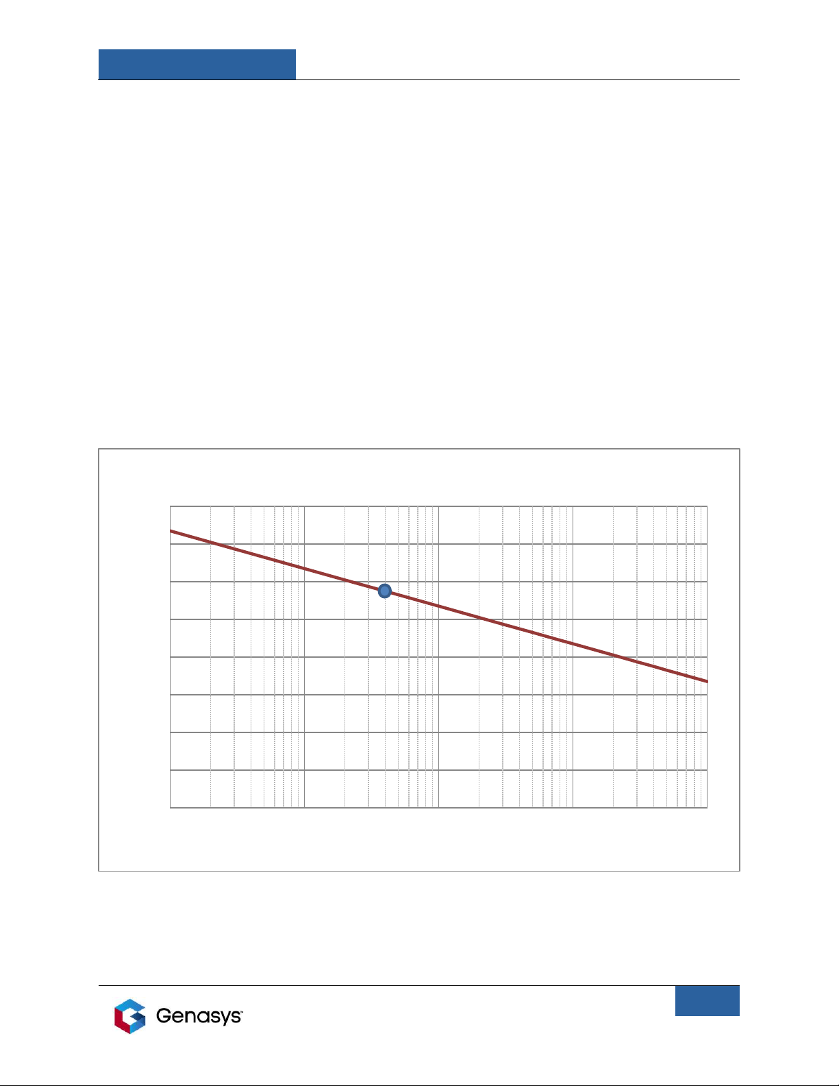
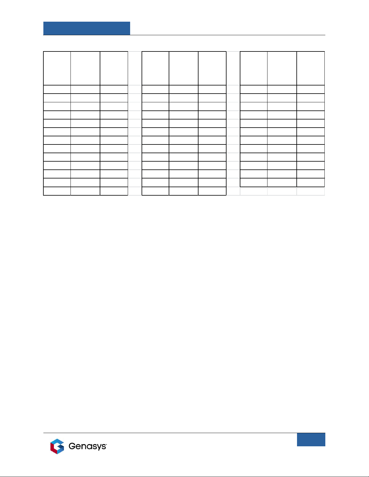
1.1 Acoustic Volume Levels........................................................................................................ 2
2.0 Introduction ............................................................................................................................. 5
3.0 Preparation for Use.................................................................................................................. 5
3.1 Unpacking Instructions ........................................................................................................ 5
3.2 Items included...................................................................................................................... 5
3.3 Inspection............................................................................................................................. 7
4.0 Installation Instructions ........................................................................................................... 7
4.1 Power Input Connection ...................................................................................................... 7
4.2 Basic Cabling Installation ..................................................................................................... 9
4.3 Installing the Optional Maxabeam Kit (Sold Separately)................................................... 10
4.4 Installing the Manual Pan-Tilt Head Mount....................................................................... 11
4.5 Installing the Optional Pole Mount Kit (Sold Separately) .................................................. 13
4.6 The LRAD Head Unit........................................................................................................... 14
5.0 Control Module/MP3 Player Overview.................................................................................. 14
5.1 Control Module Operation................................................................................................. 15
5.1.1 MIC/USB Connection ................................................................................................... 16
5.1.2 Audio Out Connection ................................................................................................. 17
5.2 Button Functions................................................................................................................ 17
5.3 LCD Display......................................................................................................................... 18
5.4 Downloading Files .............................................................................................................. 20
5.5 Changing the Alert Tone .................................................................................................... 20
5.6 Audio File Playback ............................................................................................................ 21
5.7 Using the Alert Tone .......................................................................................................... 21
5.8 Other Control Module Features......................................................................................... 21
6.0 Recording Audio Files Using LRAD Normalizer Software....................................................... 22
6.1 System Requirements ........................................................................................................ 22
6.2 Installing the Software ....................................................................................................... 22
6.3 Running the Software ........................................................................................................ 22
6.4 Recording an Audio File ..................................................................................................... 23
7.0 The Recording Microphone ................................................................................................... 25
8.0 Operating Instructions ........................................................................................................... 27
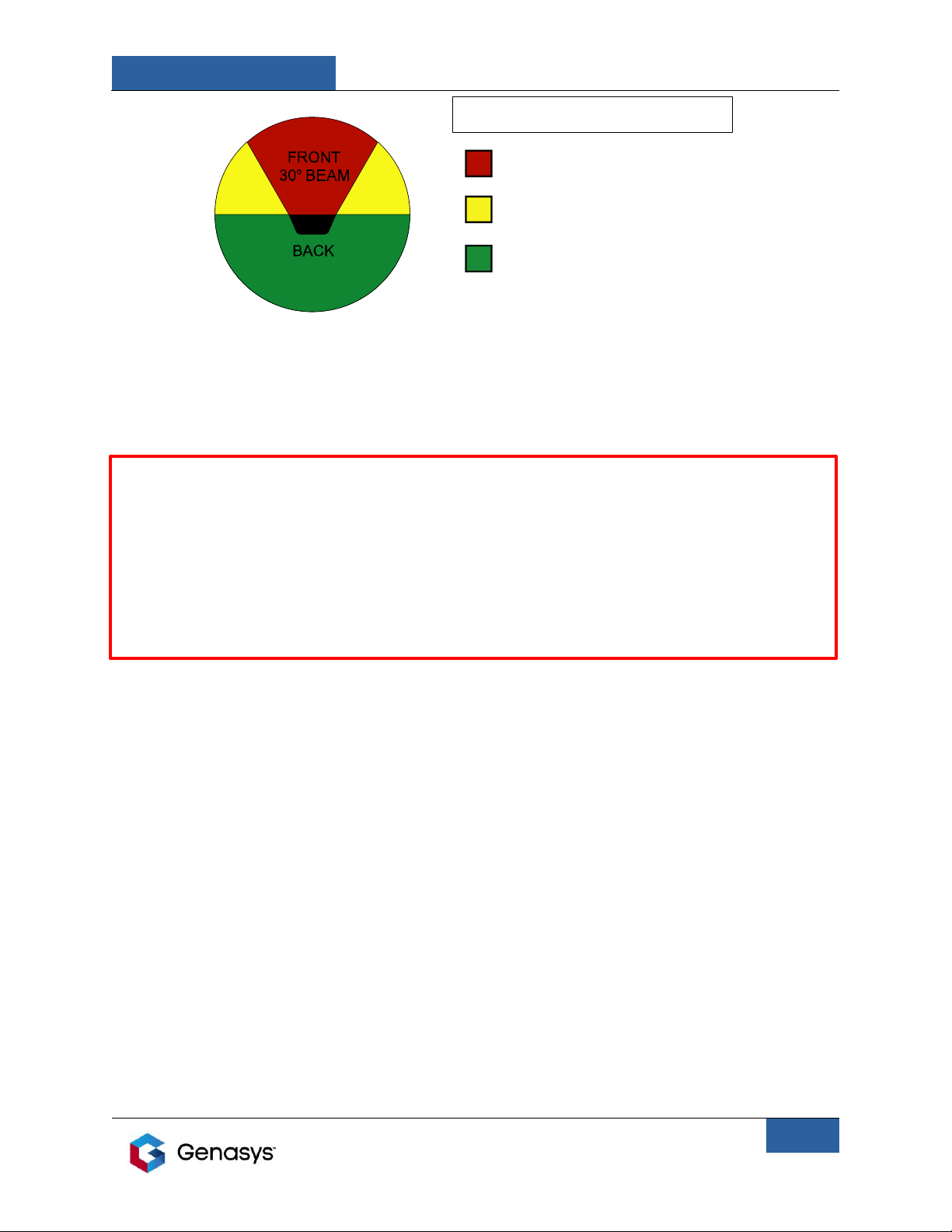
8.1 Positioning the LRAD for Operation................................................................................... 27
8.2 Aiming ................................................................................................................................ 28
8.3 Environmental Conditions Affecting Aiming...................................................................... 28
9.0 Maintenance, Troubleshooting and Servicing Instructions................................................... 29
9.1 Preventive Maintenance.................................................................................................... 29
9.2 Cleaning the Head Unit Grill............................................................................................... 29

LRAD 450XL
GENASYS INC.
ii
10.0 Troubleshooting................................................................................................................... 29
10.1 Symptom: No green power LED after turning on the main power switch...................... 29
10.2 Symptom: There is low or no sound coming from the LRAD........................................... 30
10.3 Symptom: No display or backlights on Control Module.................................................. 30
10.4 Symptom: No audio or low audio from LRAD.................................................................. 31
10.5 Symptom: Control Module not recognized by computer or computer gives error
message when connecting Control Module. ............................................................................ 31
11.0 System Tests......................................................................................................................... 32
11.1 Driver Resistance Test...................................................................................................... 32
11.2 Amplifier Output Voltage Test ......................................................................................... 33
12.0 Instructions for Replacing a Faulty Driver............................................................................ 34
13.0 Preparation for Shipment .................................................................................................... 40
14.0 Storage ................................................................................................................................. 40
15.0 Specifications ....................................................................................................................... 41
16.0 Technical Support ................................................................................................................ 42
List of Figures
Figure 1: LRAD-450XL SPL vs. Distance ........................................................................................... 2
Figure 2: LRAD-450XL Operation Zones.......................................................................................... 4
Figure 3: LRAD-450XL DC Power Cable Termination ...................................................................... 7
Figure 4: LRAD-450XL DC Power Cable Pinout ............................................................................... 8
Figure 5: Cable Connections ........................................................................................................... 9
Figure 6: Maxabeam Installation .................................................................................................. 10
Figure 7: Manual Pan/Tilt Head Mounting ................................................................................... 11
Figure 8: Pole Mount Kit Installation ............................................................................................ 13
Figure 9: 450XL Head Unit Features ............................................................................................. 14
Figure 10: Control Module Features............................................................................................. 15
Figure 11: Auxiliary Audio Cable (Optional).................................................................................. 16
Figure 12: USB Download Cable ................................................................................................... 16
Figure 13: MIC/USB Connector Pinout ......................................................................................... 16
Figure 14: LRAD Control Interface Pinout..................................................................................... 17
Figure 15: Control Module Display ............................................................................................... 18
Figure 16: Control Module Splash Screen..................................................................................... 19
Figure 17: Control Module Mass Storage Screen ......................................................................... 20
Figure 18: Normalizer Interface Screen ........................................................................................ 22
Figure 19: LRAD Normalizer During Recording............................................................................. 24
Figure 20: Recording Microphone Features and Controls............................................................ 26
Figure 21: Optional Soft Cover...................................................................................................... 29
Figure 22: Head Unit Speaker Connector ..................................................................................... 32
Figure 23: Amplifier Module......................................................................................................... 33
Figure 24: Head Unit Speaker Connector ..................................................................................... 34
Figure 25: Replacement Driver Kit................................................................................................ 35
Figure 26: Front Screen Removal.................................................................................................. 36

LRAD 450XL
GENASYS INC.
iii
Figure 27: Driver Connection ........................................................................................................ 37
Figure 28: Driver Removal ............................................................................................................ 38
Figure 29: Application of RTV on Driver........................................................................................ 39
List of Tables
Table 1: Acoustic Exposure Limits................................................................................................... 3
Table 2: Standard LRAD-450XL Parts List........................................................................................ 5
Table 3: Control Module Button Functions .................................................................................. 18

LRAD 450XL
GENASYS INC.
Manual Part No.: 112343-00 Rev. E
1
1.0 Important Safety Information
The LRAD-450XL is capable of producing sound pressure levels that have the potential to cause
temporary or permanent hearing damage if not used properly. Always follow the safety
precautions described in this manual as well as on the unit’s operator interfaces.
Read these instructions.
Keep these instructions in a place known to and accessible by the potential operators of the
LRAD-450XL.
Heed all warnings contained in this document.
Follow all instructions detailed in this document.
Install in accordance with the instructions contained in this document.
Do not install near any heat sources such as radiators, heat registers, stoves, or other
apparatuses that produce heat.
Protect the power cord from being treaded upon, excessively bent, creased, or pinched,
particularly at the point where the cable assemblies connect to the LRAD and its components.
Only use attachments/accessories specified by the manufacturer.
Refer all servicing to qualified service personnel. Servicing is required when the LRAD-450XL has
been noticeably or substantially damaged in any way, including cord or plug damage, serious
denting, breached housings, or if liquid has penetrated the interior of the device or any
accessories.
Do not block airflow through the heatsink on the electronics module.

LRAD 450XL
GENASYS INC.
Manual Part No.: 112343-00 Rev. E
2
1.1 Acoustic Volume Levels
The LRAD-450XL acoustic device is capable of producing a maximum continuous sound pressure
level (SPL) of 145 dB in order to achieve adequate communications over long distances. The
sound pressure levels achieved at full volume at distances of 40 meters or less may cause
hearing damage if people are exposed to these for long periods of time. The following graphic
shows the LRAD-450XL’s maximum volume levels over distance. The LRAD-450XL’s volume
decays by approximately 6 dB per doubling of the distance down-range.
The following range chart is marked to correspond with the Department of Defense’s MIL-STD-
1474D (Noise Limits), which dictates maximum daily exposure durations for various sound
levels. Personnel within a 40 meter range should wear hearing protection at all times or should
not be exposed to output from the LRAD on a daily basis. Personnel in the range of 40 to 1000
meters should wear hearing protection or limit their daily exposure times to the durations
listed in the tables that follow. Personnel beyond the 1000 meter range may be exposed to the
LRAD’s output continuously on a daily basis without risking hearing damage.
Figure 1: LRAD-450XL SPL vs. Distance
0
20
40
60
80
100
120
140
160
110 100 1000 10000
SPL in dBA
Range in Meters
SPL vs. Distance -LRAD-450XL
115dB at 40m

LRAD 450XL
GENASYS INC.
Manual Part No.: 112343-00 Rev. E
3
Table 1: Acoustic Exposure Limits
Note: The safe exposure limits given by MIL-STD-1474D assume long term exposure to the
listed SPL levels on a daily basis. Short exposures to SPL levels above 115 dB may cause
temporary hearing loss, therefore the operator of the LRAD must employ and follow specific
Rules of Engagement which take this risk into account.
PROTECTION OF NEARBY PERSONNEL:
Qualified LRAD operators must ensure the device is positioned, aimed, and operated in a
manner as to avoid exposing nearby personnel and bystanders to excessive levels of acoustic
energy. The following guidelines are to be used in conjunction with sound judgment:
Never operate LRAD at maximum power where personnel may be within 40 meters or where
an acoustically reflective object (e.g. building, wall, or bulkhead) is located, such that the
reflected distance to personnel is less than 40 meters.
Never point LRAD directly at personnel in the immediate vicinity of the LRAD’s position.
Always scan the surrounding area for nearby personnel prior to activating the LRAD’s acoustic
output.
The following diagram (Figure 2) shows the relative acoustic power levels in the various zones
around the LRAD. The area to the front of the LRAD (RED area), has the highest acoustic power.
The areas to the sides of the LRAD (YELLOW areas) are at least 20 dBA lower in acoustic power
than the RED area. The area behind the LRAD (GREEN area) has the lowest acoustic power and
is 35 to 45 dBA quieter than the RED area.
Max
Sound
Level
(dBSPL)
Time limit
(minutes)
Distance
(meters)
Max
Sound
Level
(dBSPL)
Time limit
(minutes)
Distance
(meters)
Max
Sound
Level
(dBSPL)
Time limit
(minutes)
Distance
(meters)
<80 no limit 92 95 562 105 4.7 126
80 1440 2239 93 76 501 106 3.8 112
81 1210 1995 94 60 447 107 3100
82 960 1778 95 48 398 108 2.4 89
83 762 1585 96 38 355 109 1.9 79
84 605 1413 97 30 316 110 1.5 71
85 480 1259 98 24 282 111 1.2 63
86 381 1122 99 19 251 112 0.9 56
87 302 1000 100 15 224 113 0.7 50
88 240 891 101 12 200 114 0.6 45
89 190 794 102 9.5 178 115 0.5 40
90 151 708 103 7.5 158 >115 forbidden 40
91 120 631 104 6.0 141

LRAD 450XL
GENASYS INC.
Manual Part No.: 112343-00 Rev. E
4
Figure 2: LRAD-450XL Operation Zones
HEARING PROTECTION: The LRAD is provided with foam earplugs which afford the operator of
the LRAD enough hearing protection to allow for safe, continuous operation of the unit.
WARNING!
Avoid unintentional exposure of personnel to unsafe noise levels.
Improper operation may lead to temporary or permanent loss of hearing.
OPERATORS SHOULD NOT ATTEMPT TO LISTEN TO THE OUTPUT FROM THE FRONT OF THE
DEVICE! HEARING DAMAGE MAY RESULT FROM SUCH ACTION.
The LRAD-450XL sound projection is directional. Operators standing behind the unit hear only a
small fraction of the sound energy being transmitted. This can make the operator think the
LRAD-450XL is not producing the required output.
LRAD 300X Operation Zones
DO NOT ENTER WITHIN 40 METERS
DURING CONTINUOUS OPERATION
DO NOT ENTER WITHIN 5 METERS DURING
CONTINUOUS OPERATION WITHOUT
HEARING PROTECTION
OPERATOR HEARING PROTECTION
REQUIRED WITHIN ONE METER
LRAD-450XL OPERATION ZONES

LRAD 450XL
GENASYS INC.
Manual Part No.: 112343-00 Rev. E
5
2.0 Introduction
The LRAD-450XL Long Range Acoustic Device is a powerful acoustic hailer that can be used to
project loud, clearly intelligible voice messages to targets at distances up to 1700 meters. The
acoustic output from the LRAD projects from the Acoustic Array in a focused 30 degree “cone”
of sound. Sound levels outside of this cone are greatly reduced as a result of the focused
nature of the LRAD’s sound projection. The LRAD includes a ruggedized hand-held Control
Module that can be used to store digital audio, as well as a handheld microphone for
reproducing live spoken messages. The LRAD’s MP3 Control Module features a built in ALERT
TONE button that instantly broadcasts a loud, piercing alert sound that can be used to gain a
target’s attention.
The LRAD-450XL is a DC powered unit that is meant to be powered from a 12 to 28 VDC power
source (not included) such as a vehicle or boat battery.
3.0 Preparation for Use
3.1 Unpacking Instructions
The LRAD-450XL system ships in a reusable hard case. The provided case should be stored and
used whenever shipping or transporting the LRAD. Spare crates can be ordered from Genasys
Inc. See the parts list in Table 2 for more information.
3.2 Items included
The following list itemizes the parts that are included in the LRAD-450XL system kit.
NOTE: This manual contains installation instructions for optional mounts and accessories that
may be purchased separately.
Table 2: Standard LRAD-450XL Parts List
Find
Num
Item Description
Image
1
ASSEMBLY, HEAD UNIT, INTEGRATED ELECTRONICS, LRAD-450XL, SS
2
CONTROL UNIT, REMOTE ELECTRONICS, UNIVERSAL, SS

LRAD 450XL
GENASYS INC.
Manual Part No.: 112343-00 Rev. E
6
3
CABLE ASSEMBLY, REMOTE CONTROL, 20 FT, SS
4
CABLE ASSEMBLY, DC INPUT, 4X14 GA, 12 FT, FUSED, SS
5
CABLE ASSEMBLY, USB 2.0, DOWNLOAD, MP3, D38999, 48 IN
6
MICROPHONE, RECORDING, NOISE CANCELLING ELEMENT, METAL
BUTTONS, SS
7
EAR PLUG, FOAM, W/0 CORD, NRR 33 dB (QTY: 10)
8
HARD CASE, REUSABLE, LRAD-300X
9
MANUAL, PRINTED, LRAD-450XL
10
CABLE ASSEMBLY, CD PLAYER, D38999 TO 3.5 MM PHONE, SS

LRAD 450XL
GENASYS INC.
Manual Part No.: 112343-00 Rev. E
7
11
PAN-TILT HEAD, MANUAL, LRAD-450XL, NATURAL
12
CABLE ASSEMBLY, REMOTE CONTROL, STRT/90 DEG, 16 IN, SS
13
BRACKET, SUPPORT, CONTROL UNIT, REMOTE, LRAD 1000-Xi
3.3 Inspection
Ensure that all items in the parts list are included in your shipment. Inspect the shipping case
for any signs of damage. If any of the items are missing or the shipment appears to be
damaged in any way, please contact your Genasys sales representative for assistance.
4.0 Installation Instructions
4.1 Power Input Connection
Connect the ring terminal on the RED cable to the positive (+) terminal of a 12 to 28 VDC power
source. The ring terminal on the BLACK cable bundle connects to the negative (-) terminal of the
power source. The in-line 40 A fuse is provided for protection and safety.
Figure 3: LRAD-450XL DC Power Cable Termination
Red, Positive (+)
Black, Negative (-)
40 A Fuse

LRAD 450XL
GENASYS INC.
Manual Part No.: 112343-00 Rev. E
8
The MIL-D-38999 connector on the other end of the cable connects to the power input
connector of the LRAD.
Refer to the following pinout for any troubleshooting or repairs:
Figure 4: LRAD-450XL DC Power Cable Pinout
Pinout for Power Input Connector:
Connector type: D38999/26WE6SN
Pin A: Red wire, Positive (+)
Pin B: Orange wire, Positive (+)
Pin C: Drain wire, Negative (-)
Pin D: Black wire, Negative (-)
Pin E: Brown wire, Negative (-)
Pin F: No connection

LRAD 450XL
GENASYS INC.
Manual Part No.: 112343-00 Rev. E
9
4.2 Basic Cabling Installation
Connect cables as shown in the figure below.
Figure 5: Cable Connections
•The provided MP3 Control Unit can be attached to the LRAD-450XL for local operation or
placed remotely using the provided 20 foot control unit cable.
•For local operation, attach the provided control unit mounting bracket to the rear of the
450XL using the captive thumbscrews.
•Connect the straight end of the 16 inch remote MP3 cable to the audio out connector of the
remote MP3 control unit.
•Place the MP3 control unit onto the mounting bracket and tighten the knobs.
•Connect the 90 degree end of the 16 inch remote MP3 cable to the connector on the rear
panel of the 450XL.
•Connect the Microphone to the MIC/USB connector of the handheld MP3 player control
unit.
•Connect the ring terminals of the power cord to the battery or DC power source.
•Connect the power cord plug to the Power Input connector on the LRAD head unit.
Control Unit
Connector
DC Power input
connector:
10-28VDC
Optional: Install control unit mounting
bracket on the 450XL using the provided
thumbscrews.
Connect the straight plug of the provided short control unit
cable to the connector at the rear of the control unit.
Place the control unit in the mounting bracket and connect
the 90 degree plug to the control unit connector as shown.
Connect the DC input power
cord to the connector at the
back of the 450XL.

LRAD 450XL
GENASYS INC.
Manual Part No.: 112343-00 Rev. E
10
4.3 Installing the Optional Maxabeam Kit (Sold Separately)
Figure 6: Maxabeam Installation
1. Remove only the 4 screws and washers shown (Items 3 and 4) and the top handle (not
shown) from the Side Support Plate on the top of the LRAD head unit.
2. Attach the Maxabeam Bracket (Item 1) with Power Supply assembly (Item 2) using the
hardware removed during Step 1.
3. While pulling up on the spring-loaded plunger pin, insert the mounting feet of the
Maxabeam into the four keyhole-shaped holes on the mounting bracket and slide it back.
Lock the spring-loaded plunger pin into place and tighten by turning the knob.
4. Connect the Maxabeam to power source. The Maxabeam only operates using 12 VDC input
power. The DC-DC Power Supply included in this kit will automatically convert 12 to 28 VDC
of input power into 12 VDC for the Maxabeam.
WARNING: Plugging the Maxabeam directly into non-12 VDC power sources, such as some
vehicle batteries, will damage the Maxabeam.

LRAD 450XL
GENASYS INC.
Manual Part No.: 112343-00 Rev. E
11
4.4 Installing the Manual Pan-Tilt Head Mount
Figure 7: Manual Pan/Tilt Head Mounting
1. Remove the six hex-head screws and flat washers (Items 1 and 2) from the Side Support
Plate (Item 4) on the bottom of the LRAD head unit.
2. With the handle facing the rear of the unit, align the holes of the Pan-Tilt Head (Item 3) with
the holes of the Side Support Plate (Item 4) and then attach using the hardware removed
during step 1.
NOTE: The Sideplate is tapered to match the slope of the side of the LRAD. Ensure that the
arrow marked “F” that is engraved on the Sideplate is pointing toward the front of the LRAD
when installing.

LRAD 450XL
GENASYS INC.
Manual Part No.: 112343-00 Rev. E
12
3. The stud at the bottom of the Pan-Tilt Head will fit into the Medium Duty Tripod (118067-
00)(sold separately) or the Pole Mount (106664-00) (also sold separately).
4. Adjust the tilt position of the LRAD by loosening the Tilt Friction Adjustment Knob and tilting
the unit using the handle.
5. Adjust the amount of friction by tightening or loosening the nut found next to the
Adjustment Knob.

LRAD 450XL
GENASYS INC.
Manual Part No.: 112343-00 Rev. E
13
4.5 Installing the Optional Pole Mount Kit (Sold Separately)
Figure 8: Pole Mount Kit Installation

LRAD 450XL
GENASYS INC.
Manual Part No.: 112343-00 Rev. E
14
1. The Pole Mount can be used to attach the LRAD to poles from 2" to 6" in diameter.
2. Affix Pole Mount Weldment (Item 1) using the two Pipe Clamps (Item 2) and the hardware
items provided (Items 3 to 6).
3. Insert the stud from the Manual Pan-Tilt mount into the receptacle in the Pole Mount and
lock in the unit in the desired orientation using the T-handles and wingnuts (Items 7 and 8).
4. Adjust the elevation angle of the LRAD using the elevation adjustment knob.
4.6 The LRAD Head Unit
Figure 9: 450XL Head Unit Features
The LRAD-450XL head unit is a compact and lightweight acoustic device with a fully integrated
amplifier module built in. It provides mounting locations for the Microphone and Control
Module as shown in Figure 9. A green LED will light when the system is powered on. A
resettable breaker will trip in the event of an internal short circuit.
5.0 Control Module/MP3 Player Overview
The use of prerecorded messages is recommended whenever possible. Prerecording ensures
that messages are appropriately worded and clearly broadcasted to maximize the effectiveness
of communications.
The LRAD-450XL is supplied with a Dash-Mounted Control Module. The Control Module allows
operators to utilize approved prerecorded messages in the field. Some operators have found it
useful to record a message in several different languages to meet their communication needs.

LRAD 450XL
GENASYS INC.
Manual Part No.: 112343-00 Rev. E
15
The Control Module is preloaded with a number of warning and test messages that may be
freely used or deleted as needed.
The figures below show the main elements of the Control Modules. A sealed, ruggedized
package houses an MP3 player capable of playing audio in MP3, WAV and WMA formats.
Figure 10: Control Module Features
5.1 Control Module Operation
•Attach Control Module to LRAD Amplifier Module as shown in Figure 5, Section 4.2.
•If needed, attach the microphone to the microphone input connection of the Control
Module (marked: “MIC/USB”).
•Turn on the LRAD’s amplifiers and the Control Module by turning the Power and Volume
Control knob to the right. You will feel the knob click to turn the unit on.
•Adjust the Volume Control to the desired setting.
•Adjust the backlight intensity of the buttons and the LCD Display by pushing the BACKLIGHT
BRIGHTNESS button. Pushing this button cycles through three brightness levels and “off”
(no backlight).
MIC/USB INPUT
MIC CLIP
MP3 CONTROL UNIT
INDICATOR LEDS
VOICE BOOST
SWITCH
POWER/VOLUME CONTROL
SOUND PROJECTION
SWITCH
MP3 CONTROL
UNIT DISPLAY LCD
PLAY/PAUSE
STOP
SKIP FWD.
SKIP REV.
BACKLIGHT
REPEAT MODE
ALERT TONE

LRAD 450XL
GENASYS INC.
Manual Part No.: 112343-00 Rev. E
16
5.1.1 MIC/USB Connection
The MIC/USB connector allows connection of the microphone or another accessory device such
as a Phraselator, a CD player, or a commercial audio device, such as the iPod. Audio played
from an external device using this connection will be mixed with any audio being played
through the LRAD’s Control Module: it will not override any other audio being played. This
connection is accomplished through the optional Auxiliary Audio cable.
Figure 11: Auxiliary Audio Cable
The MIC/USB connector allows a USB connection to a PC, which can be used to download
prerecorded audio files onto the Control Module. This connection can also be used to update
the firmware in the Control Module.
USB
Figure 12: USB Download Cable
The connector provided is of the following MIL-38999 Type III designation:
D38999/24KB35S
This connector provides thirteen #22 socket contacts. Figure 13 shows the pinout for this
connector:
Pin 1: +5.0 VDC output
Pin 2: Analog Audio Input Signal +
Pin 3: Analog Audio Input Signal -
Pin 4: Audio ground
Pin 5: Not used
Pin 6: Mic
Pin 7: Mic GND
Pin 8: Not used
Pin 9: Not used
Pin 10: +5 VDC input
Pin 11: USB -
Pin 12: USB +
Pin 13: USB GND
Note: Audio Input signal level is not to exceed 280 mV RMS.
Figure 13: MIC/USB
Connector Pinout
Table of contents
Other GENASYS Marine Equipment manuals