manuals.online logo
Brands
  1. Home
  2. •
  3. Brands
  4. •
  5. GENASYS
  6. •
  7. Marine Equipment
  8. •
  9. GENASYS 60XL User manual

GENASYS 60XL User manual

60XL MOBILE RANGE SYSTEM
USER GUIDE
1 (858) 676-1112 |www.genasys.com | info@genasys.com | PN: 120022-00 Rev. 01 | Copyright © 2021 Genasys Inc.
SYSTEM CONTENTS
1.
2.
1. 60XL Horn
2. MP3 Player
3. Self-Contained Amplifier Pack
(Amp Pack)
4. Tripod
5. USB Cable (4 ft)
6. Microphone
7. AUX Cable, 3.5 mm (3 ft)
8. Amp Pack Power Cable (12 ft)
9. MP3 Player Cable (20 ft)
10. Horn Cable (100 ft)
11. Horn Cable Reel
12. Optional: Junction Box
13. Optional: Junction Box Cable (10 ft)
4.
8.
9.
SYSTEM SET UP
5. Connect male end of the horn cable to
the amp pack’s large D38999 connector,
to the right of the pack’s handle.
•If using the dual horn system, skip
this step and continue to step 6.
•‘DUAL HORN SYSTEM SET UP’ is shown
on reverse side of this guide.
6. Connect the MP3 player cable between
the MP3 player’s ‘AUDIO OUT’ connector
and either the amp pack’s inside or
outside MP3 player connector.
•Inside: ‘MP3 PLAYER’ connector.
•Outside: Connector to the left of the
pack’s handle.
7. Connect the microphone to either the
MP3 player or the amp pack.
•MP3 Player:‘AUDIO IN’ connector.
•Amp Pack:‘MICROPHONE’ connector
inside the pack.
11.
6.
12.
10.
3.
5.
7.
13.
1. Set up the tripod at the desired
broadcast location.
•Extend the three legs and secure
them by tightening the leg knobs.
•Open the tripod and secure it by
tightening the center knob.
2. Place the 60XL horn’s stud into the
tripod’s mounting receptacle.
•Secure the horn by tightening the
tripod’s upper knob.
3. Connect female end of the horn cable to
the horn’s D38999 connector, located on
the underside of the horn.
•The operator can manage this cable
by using the horn cable reel.
4. Position and open the amp pack at the
operator’s location.
1 (858) 676-1112 |www.genasys.com | info@genasys.com |PN: 120022-00 Rev. 01 | Copyright © 2021 Genasys Inc.
1. Power on the 60XL Mobile Range Systemby flipping the amp pack’s power switch to the ON position.
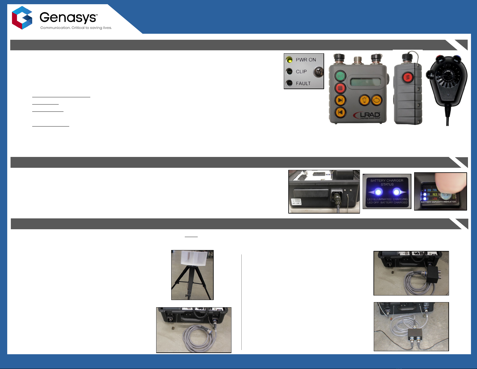
•‘PWR ON’ LED on amplifier panel will illuminate green when pack is powered on.
•This will also provide power to the horn, MP3 player, and microphone.
•NOTE: Prior to operating the system, ensure the pack’s volume knob is set to low.
2. Play and broadcast the desired audio.
•Stored Audio Message: Press the MP3 player’s green ‘Play’ button to broadcast the stored audio message.
•Alert Tone: Press and hold the red ‘Alert Tone’ button on the side of the MP3 player to broadcast the tone.
•Microphone: Press and hold the Push-To-Talk (PTT) button to broadcast live speech.
•This microphone can also record and play messages on-the-fly.
•External Audio: Connect the AUX cable between the MP3 player’s ‘AUDIO IN’ connector and an external device
(phone, tablet, etc.) and play the desired audio file.
3. Adjust the amp pack’s volume knob until audio is playing at the desired volume level.
To change the audio files stored on the MP3 player, connect the MP3 player to a computer using the USB cable.
60XL MOBILE RANGE SYSTEM
USER GUIDE
SYSTEM OPERATION
DUAL HORN SYSTEM SET UP (Optional Equipment Required for this Configuration)
To set up the dual horn system, perform the following steps after completing the ‘SYSTEM SET UP’ section.
•In addition to the standard system contents, the dual horn system configuration requires a second horn, a second horn cable, a second tripod, the junction
box, and the junction box cable.
CHARGING THE AMP PACK
Connect the amp pack power cable between the power input on the right side of the amp pack and a
power source.
Charging is indicated by blue LEDs inside the amp pack and the whirl of the pack’s internal fans.
To check the charge level press and hold the ‘TEST’ button, found on the top of each of the pack’s
batteries. This will cause the LEDs to illuminate, indicating whether the charge level is low, medium, or
full.
1. Set up the second horn, cable, and
tripod by repeating ‘SYSTEM SET UP’
steps 1 through 3.
2. Connect the male end of the junction
box cable to the amp pack’s large
D38999 connector, to the right of the
pack’s handle.
3. Connect the female end of the junction
box cable to the male connector on the
junction box.
4. Connect the two horn cables to the
female connectors on the junction box.

Other GENASYS Marine Equipment manuals

GENASYS LRAD User manual

GENASYS

GENASYS LRAD User manual

GENASYS LRAD 450XL Technical Document

GENASYS

GENASYS LRAD 450XL Technical Document

Popular Marine Equipment manuals by other brands

Pfannenberg DS5-SIL instruction manual

Pfannenberg

Pfannenberg DS5-SIL instruction manual

EMS FireCell FC-179-002 installation guide

EMS

EMS FireCell FC-179-002 installation guide

Garmin GMI 10 Digital Marine Instrument Display installation instructions

Garmin

Garmin GMI 10 Digital Marine Instrument Display installation instructions

Garmin Forerunner 30 owner's manual

Garmin

Garmin Forerunner 30 owner's manual

Loggerhead DSG-ST manual

Loggerhead

Loggerhead DSG-ST manual

Humminbird PiranhaMAX Portable 150 PT Installation and operation manual

Humminbird

Humminbird PiranhaMAX Portable 150 PT Installation and operation manual

Simrad Navico WP10 manual

Simrad

Simrad Navico WP10 manual

Raymarine M81130 installation guide

Raymarine

Raymarine M81130 installation guide

Bennett 621 instructions

Bennett

Bennett 621 instructions

MEDC DB15 Technical manual

MEDC

MEDC DB15 Technical manual

Furuno CI-80 Operator's manual

Furuno

Furuno CI-80 Operator's manual

Garmin GSD 21 - GPS Receiver Remote Sonar Sensor installation instructions

Garmin

Garmin GSD 21 - GPS Receiver Remote Sonar Sensor installation instructions

Odom ECHOSCAN manual

Odom

Odom ECHOSCAN manual

Raymarine St290 Owner's handbook

Raymarine

Raymarine St290 Owner's handbook

B&G HB-1000I installation manual

B&G

B&G HB-1000I installation manual

Dual AMCP600W Installation & owner's manual

Dual

Dual AMCP600W Installation & owner's manual

Kongsberg EM 710 Maintenance manual

Kongsberg

Kongsberg EM 710 Maintenance manual

Harken MKIV Unit 1 installation manual

Harken

Harken MKIV Unit 1 installation manual

manuals.online logo
manuals.online logoBrands
  • About & Mission
  • Contact us
  • Privacy Policy
  • Terms and Conditions

Copyright 2025 Manuals.Online. All Rights Reserved.