General DCS18HPART User manual

z
HIGH-PERFORMANCE WIRELESS
RECORDING VIDEO BORESCOPE
SYSTEM with VGA RESOLUTION
ARTICULATING PROBE
USER’S MANUAL
DCS18HPART
Please read this manual carefully and thoroughly before using this product.
99 Washington Street
Melrose, MA 02176
Phone 781-665-1400
Toll Free 1-800-517-8431
Visit us at www.TestEquipmentDepot.com

TABLE OF CONTENTS
Introduction . . . . . . . . . . . . . . . . . . . . . . . . . . . . . . . . . . . . . . . . . 3 –4
Key Features . . . . . . . . . . . . . . . . . . . . . . . . . . . . . . . . . . . . . . . . . . . 4
Safety Instructions . . . . . . . . . . . . . . . . . . . . . . . . . . . . . . . . . . . . . . 4
What’s in the Case . . . . . . . . . . . . . . . . . . . . . . . . . . . . . . . . . . . . . . . 5
roduct Overview . . . . . . . . . . . . . . . . . . . . . . . . . . . . . . . . . . . . 5 –6
Setup Instructions . . . . . . . . . . . . . . . . . . . . . . . . . . . . . . . . . . . . 7 –8
Charge Console and robe Batteries . . . . . . . . . . . . . . . . 7 –8
Sync Console and robe . . . . . . . . . . . . . . . . . . . . . . . . . . . . 8
Insert SD Card . . . . . . . . . . . . . . . . . . . . . . . . . . . . . . . . . . . . 8
Operating Instructions . . . . . . . . . . . . . . . . . . . . . . . . . . . . . . . 9 – 16
Viewing Live Video on the Console . . . . . . . . . . . . . . . . . . . . . 9
Manipulating the Articulating robe . . . . . . . . . . . . . . . . . . . 10
Using the Three Control Buttons . . . . . . . . . . . . . . . . . . . . . 11
Attaching the Mirrored Viewing Tip . . . . . . . . . . . . . . . . . . . 12
Viewing Live Video on a TV Monitor . . . . . . . . . . . . . . . 12 – 13
Taking ictures and Recording Videos . . . . . . . . . . . . . . . . . 13
Viewing hotos and laying Back Videos . . . . . . . . . . . 13 – 14
Accessing SD Card Content . . . . . . . . . . . . . . . . . . . . . . . . . 14
Navigating the Main Menu . . . . . . . . . . . . . . . . . . . . . . 14 – 16
Specifications . . . . . . . . . . . . . . . . . . . . . . . . . . . . . . . . . . . . . 16 – 17
Operating, Maintenance & Troubleshooting Tips . . . . . . . . . . . . . . 18
Compatible robes . . . . . . . . . . . . . . . . . . . . . . . . . . . . . . . . . . . . . 19
Warranty Information . . . . . . . . . . . . . . . . . . . . . . . . . . . . . . . . . . . 20
Return for Repair olicy . . . . . . . . . . . . . . . . . . . . . . . . . . . . . . . . . 20
2

INT ODUCTION
Thank you for purchasing General Tools & nstruments’ (General’s) DCS18HPART High-
Performance Wireless Recording Video Borescope System with VGA Resolution
Articulating Probe. Please read this user’s manual carefully and thoroughly before using
the instrument.
The DCS18HPART has two components: the DCS1800 Handheld Wireless Recording
Video Borescope Console and the P18HPART VGA Resolution Wireless Articulating Probe.
The P18HPART is 1m (39 in.) long and has a diameter of 6mm (0.23 in.). n addition to a
VGA resolution camera, the probe has three buttons on its controller that enable you to
brighten, rotate and remove reflections from video and images to improve their clarity
and readability.
You can expand the universe of probes compatible with the DCS1800 console to include
dozens of wired, non-articulating probes by purchasing General's DCS1800-TR Wireless
Probe Handle/Controller. The DCS1800-TR provides both the connector needed to
interface with a high-performance wired probe, and the transmitter needed to send the
video it captures to the DCS1800 console.
Two tables describing all probes compatible with the DCS1800 console can be found on
p. 19.
A thumbwheel on the right of the articulating probe
controller allows you to adjust the brightness of the
LEDs illuminating the camera at the end of the probe.
Articulation greatly expands the range of inspection
possibilities. Being able to change the probe’s viewing
axis in situ by up to 155° in two directions allows you
to see around corners or even “behind” the probe,
even in close quarters. Separately, the ability to detach
the monitor from the probe also increases application
flexibility by, for example, enabling two-handed
operation, as shown in the photo at right.
The DCS1800 console has three operating modes: Preview, Playback and Menu:
• In Preview mode, video framed by the camera’s field of view is displayed in real time
on the console’s LCD. The console automatically enters this mode when powered on.
A front-panel button allows you to double the size of a target (a zoom level of 2X). The
same button allows you to “mirror” video, making it possible to read serial numbers
seen and “reversed” by an attached probe with a mirrored viewing tip. n Preview
mode, real-time video also can be exported through an included video cable to any
NTSC- or PAL-format TV monitor with RCA input jacks.
Operating in Preview mode, the DCS1800 console also allows you to record inspection
video clips and photos at VGA (640 x 480 pixel) resolution on an included SD memory
card by pressing icon-labeled buttons on the console’s front panel. The remaining
front-panel buttons enable access to Playback and Menu modes.
• In Playback mode, you can browse the SD card for saved video and picture files and
view the media on the console’s LCD or a larger TV monitor. Video clips and photos
also can be viewed on a PC by removing the SD card and plugging it into the
3

computer directly or through a card reader. Because videos are saved as .avi files and
photos as .jpg files, applications found on most PCs (Microsoft Windows Media Player
and Microsoft Office Picture Manager) can open the files. The 4GB SD memory card
included in the DCS18HPART case can store at least 4 hours of video, recorded at
15 Mbytes/minute, in addition to hundreds of photos.
• In Menu mode, you use familiar scrolling motions and responses to dialog boxes to
navigate a main menu with six submenus. When selected, submenu items execute
“housekeeping” functions such as deleting files, setting the date and time, enabling or
disabling date and time stamps, choosing any of 28 languages for display indications,
selecting a Video out format and adjusting the triggering time of the console's Auto
Power Off (APO) function.
KEY FEATU ES
• Slim (6mm diameter), wireless, waterproof P67 probe with articulation range of
155°, high-quality VGA resolution camera at its tip, and light boost, anti-reflection
and 90° image rotation buttons on controller. Camera lighting provided by four
adjustable-brightness white LEDs.
• Operating flexibility is maximized when console is detached from probe. n this
mode, video captured by probe can be sent wirelessly to console from up to 33 ft.
(10m) away on any of four channels.
•
Console has 3.5 in. diagonal color LCD for viewing probe video instantly and saved
video clips and pictures later
• Compatible with dozens of high-performance camera-tipped probes from General
(see p. 19)
• 28 available menu languages
• Familiar menu-driven user interface for viewing and recording photos and voice-
annotated video clips on standard SD memory card (4GB card included) and playing
back media on console, TV or PC
• Console and probe powered by separate rechargeable Lithium-ion batteries with
4-hour capacity
• 1-year limited warranty
SAFETY INST UCTIONS
CAUTION!
Never insert any robe attached to the DCS1800 console into any structure or
s ace known or sus ected to contain live electric wiring
• The DCS1800 system is intended for industrial applications only. Do not use a
compatible probe for human or any other biological inspections.
• Never insert an attached probe into any flammable gas or liquid (including fuels in
an oil, gasoline or diesel tank)
• Do not disassemble the console. Doing so creates a potentially fatal electrical
hazard (and voids the warranty as well).
4

WHAT’S IN THE CASE
The DCS18HPART system comes in a custom hard plastic protective carrying case. nside the
case are:
• The DCS1800 console. The console integrates an LCD monitor, circuitry for wirelessly
connecting to a high-performance camera-tipped probe from General, and front-panel
controls for enlarging and/or mirroring live video as well as recording and playing back
video clips and photos captured by an attached probe.
• The P18HPART VGA Resolution Wireless Articulating Probe, with a length of 1m
(39 in.) and a diameter of 6mm (0.23 in.)
• A 70° mirrored viewing tip for the probe • A 4GB SD memory card
• An AC adapter/battery charger for a 110/220VAC supply. The adapter has a 5.5VDC,
center-positive output plug.
• An A/V cable for connecting the DCS1800 console to a TV monitor. The cable has RCA plugs
at one end and a mini-stereo plug at the other end.
• A small flat-blade screwdriver for changing the wireless channel of the console and probe
• This user’s manual
P ODUCT OVE VIEW
Fig. 1 shows the names and locations of all of the controls, ports and jacks of the
DCS1800 console. Table 1 details how the function of each front-panel button changes
with the console’s operating mode. Fig. 2 shows the names and locations of the controls
and main physical features of the P18HPART VGA Resolution Wireless Articulating Probe.
Familiarize yourself with the labels, positions and functions of all buttons and connectors
before moving on to the Setup nstructions and Operating nstructions.
Fig. 1. The controls, ports and jacks of the DCS1800 console
5
(1) (2)
(3)
(4)
(5)
(6)
(7)
(8)
(9)
(10)
1 Start/Stop Video Recording
Button
2 Snapshot Button
3 ower On/Off Button
4 revious Video/ hoto Button
5 ▼Next Video/ hoto Button
6 OK/Menu Enter/Save/Enter
Menu mode Button
7 Esc Escape/Zoom/Mirror Button
8 SD Card Socket
9 A/V Out Jack
10 AC Adapter Jack

Table 1. The DCS1800 console’s multi-function buttons
Button Label In Preview Mode In Playback Mode In Menu Mode
▲Switches to Playback mode Selects next-oldest video or photo. Moves up one line.
Also increases playback speed to When setting date/time,
1.5X, 2X or 4X. moves ahead one field.
▼Switches to Playback mode Selects next-newest video or photo. Moves down one line.
Also decreases playback speed from When setting date/time,
4X, 2X or 1.5X. moves back one field.
OK/Menu Switches to Menu mode Plays/pauses video clip Executes highlighted
command
Esc Presssed briefly, doubles Switches to Preview mode Switches to Preview
size of target (zooms 2X) mode
Pressed and held, mirrors
video
Takes a picture No action When setting date/time,
(stores .jpg photo on SD card) increases field value by one
unit
Starts/stops recording an Offers option to delete selected When setting date/time,
.avi video on SD card video/photo file decreases field value by
one unit
Fig. 2. The controls and physical features
of the P18HPART VGA Resolution
Wireless Articulating Probe
1. Soft metal probe
2. Flexible-obedient, remote-controlled neck
3. Stainless steel camera head with three
forward-facing LEDs and two side-facing LEDs
4. Stainless steel accessory alignment ring
5. Black metal thread protector ring
6. Red rubber lens cap
7. Articulation angle control wheel
8. Control wheel locking lever
9. Light boost button
10. 90° rotation button
11. Anti-reflection button
12. Button lock/unlock switch
13. Mini-USB charging jack
14. Power switch/brightness adjustment thumbwheel
15. Probe battery status LED
16. Channel selector switch (on back)
6

SETUP INST UCTIONS
CHARGE CONSOLE AND PROBE BATTERIES
To prepare to power the system on for the first time,
securely attach the P18HPART probe controller to the
back of the DCS1800 console using the two motions
shown at right. Plug one end of the supplied AC
adapter/battery charger into a 110VAC receptacle. Then
swing the black rubber protective flap away from the
right side of the DCS1800 console to expose the AC
adapter jack (Fig. 1, Callout 10). nsert the cylindrical
plug at the end of the adapter/charger cable into the AC
adapter jack. This will begin charging the console’s
battery and the probe’s battery at the same time. Next,
power on the probe by rotating the probe controller’s
thumbwheel (Fig. 2, Callout 14) downward until you feel
and hear a click.
Table 2. Correlating the color of the LED on the probe controller with probe battery
charge
LED COLOR BATTERY STAT S COMMENT
Green ln use Working under full battery
Dark Red Low battery Recharge battery when
dark red light appears during usage
Oranqe Charging while in use Charging while in use
Red Charging with power off Charging with power off
None Full battery with power off Light dims when
battery is fully charged
Next, press the red the button on the console (Fig. 1, Callout 3) and hold it for at least
five seconds. The LCD will illuminate and briefly show a battery charge indicator and
two SD card status advisories (see page 9 for details) superimposed on video being
captured in real time by the camera at the end of the probe. After a few seconds, only
live video will remain.
Practice using the thumbwheel on the probe controller to adjust the intensity of the
camera’s lighting. n a brightly lit room, moving the thumbwheel has a big effect on the
brightness of the LEDs at the tip of the probe, but a much smaller effect on the
brightness of video on the screen. The on-screen impact of changing brightness is more
pronounced in dark environments.
To power off the DCS1800 console, push the button and hold it for at least five
seconds.
t will take several hours to fully charge the console and probe batteries the first time.
You cannot replace either battery, which can only be replaced by General-authorized
service personnel. Do not open the case of either component in an attempt to
7

change the battery yourself. Doing so creates a potentially fatal electrical hazard (and
voids the warranty as well) with the AC adapter plugged in.
With proper care (charging the batteries often, and never allowing them to completely
discharge), you can expect each battery to last four or five years. Fully charged batteries
should power at least four hours of operation.
SYNC CONSOLE AND PROBE
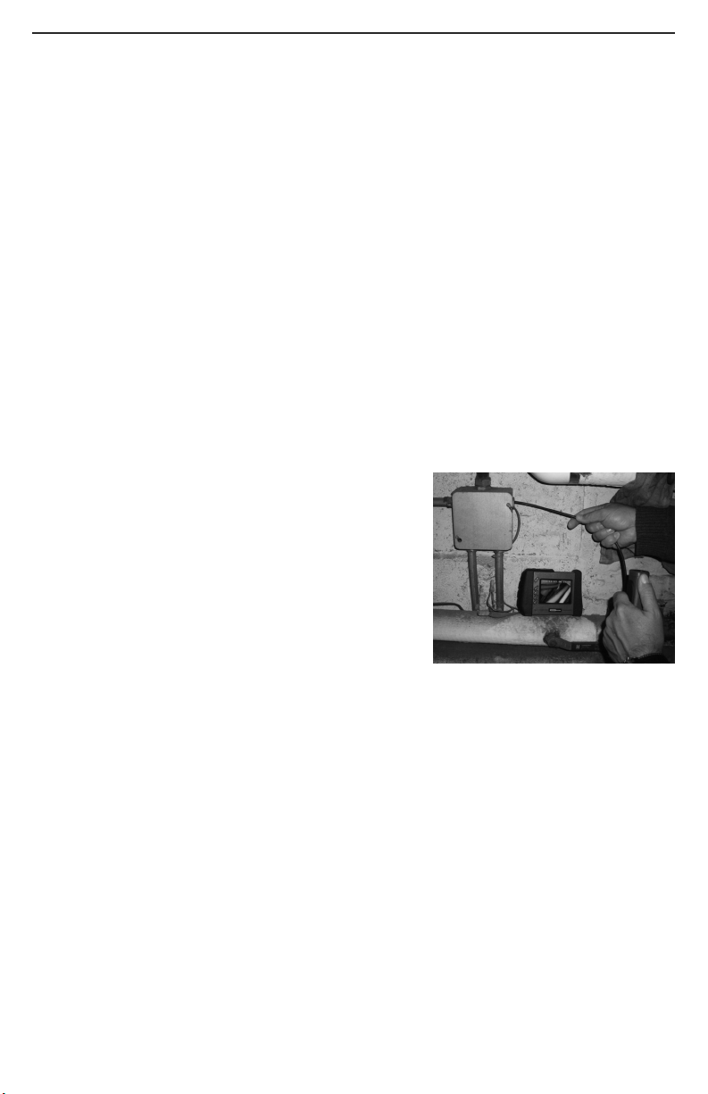
t's important to realize that the DCS1800 console is now showing video only because
the probe is physically attached to it. For most inspection applications, you will want to
detach the probe from the console and use its built-in transmitter to send video to the
console’s LCD wirelessly. Detaching the two components frees up both of your hands.
You can then use one hand to feed the probe into the area you want to inspect, and the
other hand to adjust the probe's articulation angle.
The probe and console can communicate wirelessly only if both components are
operating on the same channel. Four channels centered on 2.4GHz are available. Both
components may have already been set to the same channel at the factory. To discover
whether that is the case, detach the probe from the console. f the console’s LCD
resumes showing probe video after a brief delay, the two units are already operating on
the same channel and there is no need to sync them.
f detaching the probe from the console causes the video to disappear, leaving static on
the screen, you must sync the two components.
To synchronize the transmitting frequency of the probe with the receiving channel
of the console, you can either change the channel of the probe or the channel of the
console. n either case, you will use the small flat-blade screwdriver included in the
case. The channel selector switch of the console is on the rear of the unit, in the center
near the top. The channel selector switch of the probe controller is also on the back of
the unit (Fig. 2, Callout 16).
Since there are only four available channels, the fastest way to sync the two
components is to use the screwdriver to move the channel selector switch of either
component through all four of its possible positions. When probe video appears on the
console, you have succeeded in syncing the two units.
INSERT SD CARD
This final setup step enables storage of video clips and photos. Remove the supplied
4GB SD memory card from its packaging. Discard the packaging, but save the plastic
storage case.
Push the SD card into the socket on the right side of the console (Fig. 1, Callout 8). Be
sure the card’s gold contacts are facing the rear and enter the socket first. Push in the
card until you feel it spring back and you hear a click.
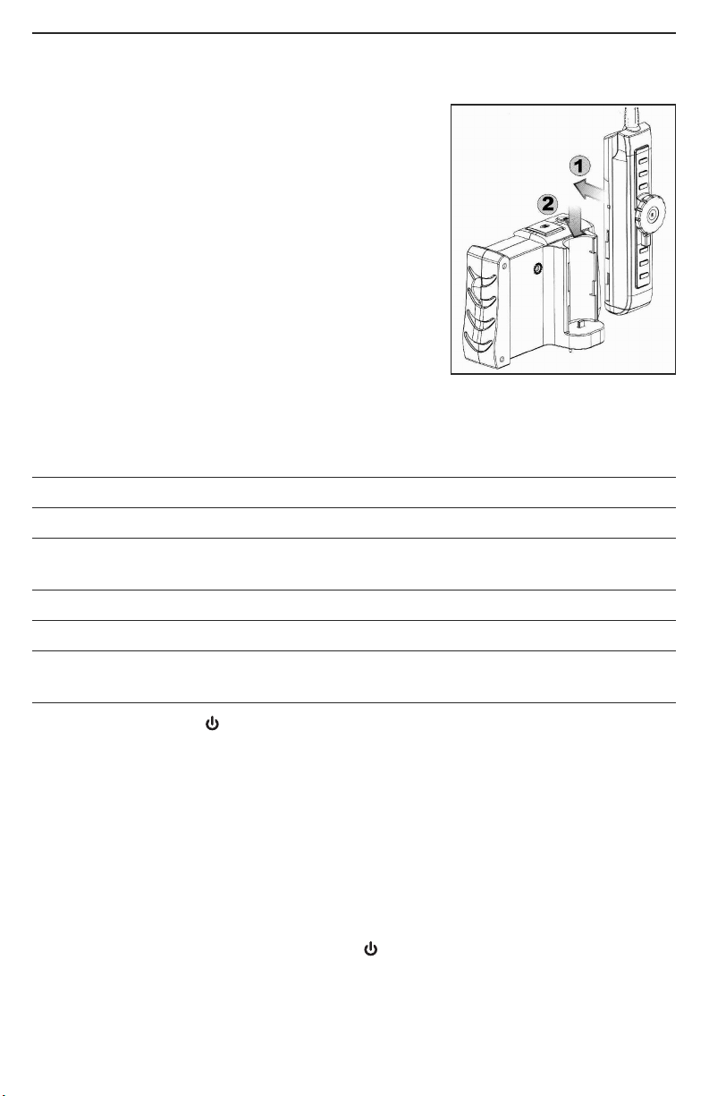
Note that when you inserted the SD card, the advisory “SD CARD INSERTED” briefly
appeared on the bottom line of the LCD and a new icon with four bars appeared briefly
on the bottom right. This icon indicates the used capacity of the memory card. Four
green bars indicate a full SD card. No green bars indicate an empty card.
To remove the card later, push it in gently until you hear a click and the card pops out far
enough for your fingers to grab.
8

OPE ATING INST UCTIONS
VIEWING LIVE VIDEO ON THE CONSOLE
Continue charging the console and probe batteries until both are fully charged. To
determine whether the console's battery is fully charged, either power the console off
and then on again, or press the ▲or ▼ button, followed by the Esc button. A battery
charge status icon will briefly appear at the lower left of the LCD, as explained and
shown below on this page.
The charge of the probe’s battery is indicated by the color of the LED on the side of the
controller (Fig. 2, Callout 15). Table 2 on p. 7 correlates the LED's color with the probe’s
charge level.
While the batteries continue to charge, General recommends that you become familiar
with the DCS1800 console's controls, indicators and menu options before taking the unit
out into the field. The system operates the same way whether powered by batteries or
the AC adapter.
To begin, power off the unit by pressing and holding the button on the console. Then
press and hold the button again to power the console back on. Each time the console is
powered on, the screen shown below will appear briefly, superimposed on live video
captured by the camera probe. Together, the number of bars in each icon represent the
DCS1800 console’s two “vital signs”—battery charge and available memory capacity.
The number of filled-in bars at the bottom of the screen
reflects the amount of data currently stored on the SD
card. A full card would be indicated by four bars. The
more filled-in bars in the icon, the higher the
current level of battery charge. Four bars indicate a fully
charged battery.
Finally, note the dual function of the Esc button in Preview
(live video) mode:
• Press the Esc button briefly and the size of targets will be doubled as the
camera’s field of view is reduced by that amount. A magnifying glass icon and the
text +2.0x will appear on-screen and remain there after the available memory
capacity bars and the battery charge icon make a brief appearance.
• Press and hold the Esc button and video will be mirrored horizontally, as shown in
the two photos below right. The effect makes it possible to read text or serial
numbers “reversed” by an attached probe with a mirrored viewing tip—by undoing
the reversal. A mirror icon will appear on-screen to indicate that video is being
mirrored.
You can mirror and zoom videos at the
same time by pressing the Esc button
briefly, and then pressing and holding
the button. n this case, a magnifying
glass icon, the text +2.0x and a mirror
icon will appear on-screen together.
9

MANIPULATING THE ARTICULATING PROBE
Next, get used to manipulating the articulating probe. Typically, borescope users insert
their probe into an orifice (a hole in a wall or an engine’s cylinder, for example) or into
an inaccessible or hazardous area (the back or an equipment rack or an engine
compartment, for example) to view components or environments that would otherwise
be invisible. Compared to an obedient probe, your soft metal articulating probe is more
flexible, but it does not retain its shape. ts obvious advantage is articulation. Using the
articulation control wheel (Fig. 2, Callout 7), you can turn the probe tip to inspect targets
off the main axis of the probe while it is in a tight space, without having to remove and
re-insert the probe.
The articulation control wheel allows you to bend the tip of the probe up to 155° to the
left or right. To bend the tip to the left, rotate the wheel counterclockwise (see photos
below left). To bend the tip to the right, rotate the wheel clockwise (see photos below
right).
To lock the tip of the probe into its bent position, move the
red lever below the control wheel to the left (see photo at right).
Remember to unlock the probe tip (by moving the red lever
to the right) before using the control wheel to move it again.
Be aware that your application environment may limit how
much you can articulate the probe. For example, if you are
inspecting a 1 in. diameter pipe, you will be unable to bend
the probe tip more than a few degrees; any more would
bring the tip into contact with the pipe's inside wall. The
relevant P18HPART specification is that 2 in. (50mm) of
clearance is required for 90° articulation (in either direction).
n many cases—inspecting the interior of an engine
cylinder, for example (see photo at right)—adequate
clearance will not be an issue. n fact, the ±155° articulation
range enables “look back” inspections of intake and exhaust
valves from within the cylinder.
10

USING THE THREE CONTROL BUTTONS
To boost the intensity of the three LEDs normally providing camera lighting, press the
button. Doing so lights a red LED behind the button and improves the brightness of
video and images, as shown below.
BEFORE BOOST AFTER BOOST
This feature can help you cope with very low-light conditions. When recording with the
boost feature activated, you must hold the probe very steady or your videos and images
will be blurred.
To rotate the probe’s field of view, use the button. Pressing the button once
backlights the button red and rotates the frame clockwise by 90°. Pressing it a second
time rotates the frame by an additional 90°, in effect turning the original view upside-
down. Pressing the button a third time rotates the field of view yet another 90°.
Pressing the button a fourth time restores the original view and extinguishes the red
button backlight.
To remove glare, reflections or spots from the field of view, use the button. Pressing
the button adds a red backlight to it, just like the other two buttons on the probe
controller.
This anti-reflection feature of the P18HPART is most useful
for eliminating reflections of the three forward-facing LEDs
in the camera head from shiny surfaces. Note that pressing
the button extinguishes the three forward-facing LEDs
and shifts responsibility for camera lighting to the two side-
facing LEDs. The net effect, as shown in the two photos
at right, is a clearer and more-readable image.
You can also use the anti-reflection function to remove glare
created by the P18HPART’s mirrored viewing tip (see the
next section of this manual for installation and alignment
instructions). The pair of images below illustrates the net
positive effect.
MIRRORED VIEW MIRRORED VIEW
WITHOUT ANTI-REFLECTION WITH ANTI-REFLECTION
11
WITH ANTI-REFLECTION
WITHOUT ANTI-REFLECTION

ATTACHING THE MIRRORED VIEWING TIP (OPTIONAL)
The only accessory included with the P18HPART is a 70° mirrored viewing tip. To attach
it to the probe:
1. Pull off the red rubber lens cap (Fig. 1, Callout 6).
2. Unscrew and remove the black metal thread protector ring
(Callout 5), as shown at right.
3. Turn the stainless steel accessory alignment ring (Callout
4) clockwise to move it away from the probe tip. Keep
turning until the ring can travel no further.
4. Screw the mirrored viewing tip onto the camera head
(Callout 3) by turning it clockwise, as shown at right. Keep
turning until the viewing tip is as far from the probe tip as
possible. n this position, it can rotate freely.
5. Press the button to activate the two-side facing LEDs.
6. Slowly turn the mirrored viewing tip counterclockwise to move it toward the probe
tip. Once the threads of the tip grip the camera head, continue turning only until the
two LEDs are clearly visible through the gap in the tip’s housing.
7. Secure the tip with the thumb and forefinger of one hand and use your other hand
to turn the alignment ring clockwise. Keep turning the ring until its leading edge
contacts the mirrored viewing tip, locking it in place. The pair of figures below
illustrate the incorrect (left) and correct (right) orientation of the mirror with respect
to the LEDs.
Remove the blue circular protective film from the mirror by pulling on its tab with a
tweezers.
VIEWING LIVE VIDEO ON A TV MONITOR
Your DCS1800 system comes with a video cable for connecting the console to a TV or
TV monitor that uses either the NTSC or PAL analog broadcast standard. By making the
connection, you can view live video (or saved videos and pictures) on a screen larger
than the console’s.
To implement the connection in hardware, insert the stereo mini-plug of the provided
cable into the A/V Out jack of the console (Fig. 1, Callout 9). Then insert the yellow RCA
plug at the other end of the cable into the Video n jack of your TV or TV monitor, and the
white RCA plug into the left or right channel audio input jack of the TV. Be sure to set the
TV input to external video.
Live video shown on a TV monitor can be enlarged, mirrored, or enlarged and mirrored
at the same time, as it can when viewed on the console’s LCD.
12
✓

To activate the connection in software and begin exporting console’s video to a TV, refer
to the instructions for the AV O TP T and TV SYSTEM lines in the “Navigating the Main
Menu” section of this manual, beginning on p. 14.
TAKING PICTURES AND RECORDING VIDEOS
To take a picture, make sure the console is in Preview mode (with live video appearing
on the LCD) and press the button (Fig. 1, Callout 2). Doing so creates a .jpg file of
the frame being displayed at that moment and stores it on the SD card. The photo’s file
name and the current date and time appear briefly on the bottom line of the LCD to
confirm that a picture was taken. The console automatically returns to Preview mode
after taking a picture.
To record a video, make sure the console is in Preview mode and press the button
(Fig. 1, Callout 1). Doing so begins creating an .avi video file for storage on the SD card.
An orange running clock appears at the lower left of the screen to confirm that a
recording is in progress, and it remains there for the duration of the video. To stop
recording, press the button again. This makes the running clock disappear and
returns the console to Preview mode.
While a video is being recorded, all console buttons other than the and Esc buttons
are disabled. Pressing the button stops the recording and returns the console to
Preview mode. You cannot pause the recording of a video clip; you must stop the clip
and start recording a new one. Briefly pressing the Esc button activates the 2X zoom
function and applies it “on the fly” to the clip being recorded. Pressing and holding the
Esc button does not mirror the field of view of the clip being recorded.
The console will be unable to store videos and pictures if its SD memory card is full,
write-protected or damaged. When the instrument senses any of these conditions, it will
superimpose the advisory SD CARD F LL at the bottom of the screen in Preview mode.
To remedy the situation, either replace the full SD card by another card with spare
capacity, or delete files individually or in bulk. nstructions for deleting files can be found
later in this user’s manual.
VIEWING PHOTOS AND PLAYING BACK VIDEOS
To view a picture or play back a video clip (or more than one in order) on the console’s
LCD or a TV monitor, switch the unit out of Preview mode and into Playback mode by
pressing the ▲or ▼button (Fig. 1, Callouts 4 and 5, respectively). n Playback mode,
pressing the ▼button repeatedly recalls all photos and videos from memory in reverse
chronological order (in other words, the newest first and the oldest last). Each press of
the ▲button selects the next oldest picture or video.
Selected photos are displayed automatically, with their file name appearing briefly at
the bottom of the LCD and their position in the chronological order of all saved files
(7/10, for example) appearing briefly at upper right. After a few seconds, only the date
and time of the photo's capture remain superimposed on the image at the bottom
of the screen.
Like photos, selected video clips are indicated by the brief appearance of their file name
at the bottom of the screen and their chronological position at upper right. Selection of a
video clip is also indicated by the presence of a film strip icon and the clip’s duration on
the top line. Unlike photos, video clips are not displayed automatically. To start playing
13

a video clip, press the OK/Menu button. To pause playback, press the OK/Menu
button again. To resume playback, press the button again.
To increase the video playback speed to 1.5X, 2X or 4X normal, press the ▲button
once, twice or three times. To decrease playback speed toward normal (1X), press the
▼button once, twice or three times.
While each photo and video is on-screen, pressing the button gives you the option to
delete its file. Pressing the button calls up a dialog box with the word DELETE on the left
and the term [OK] on the right. To delete the file, press the OK/Menu button. To keep
the file and select the next-oldest file for display, press the Esc button.
ACCESSING SD CARD CONTENT
Photos and videos stored on the SD card also can be viewed on a PC. f your computer
has an SD card slot, you can eject the memory card from the console and plug it directly
into a PC. f your PC does not have an SD card slot, you can purchase a USB SD card
reader (Part No. SDRD1) from General.
f you choose to remove the SD card from the console and plug it into a PC, either
directly or through a card reader, remember to eject the card from the PC once you are
done viewing (and/or copying) the files it contains. Depending on your PC’s startup
settings, your computer may fail to restart following its next shutdown if the SD card
remains inserted. The PC’s operating system may try to reboot from the SD card and be
unable to do so.
Details of the SD card’s file structure are worth mentioning because assigned file names
contain useful information. The figure below illustrates the hierarchy. t shows that the
SD card contains one folder named “DC M” and one subfolder named “100_DCAM”. The
100_DCAM folder contains all stored photo and video files, identified by their .JPG and
.AV extensions. You should not rename the DCIM or 100_DCAM folders while the
SD card is inside your PC. If you rename either folder, the console will fail to
recognize the SD card the next time you plug it in.
NAVIGATING THE MAIN MENU
The main menu of the DCS1800 console provides access to the following housekeeping
and operational functions:
• Bulk file erasure
• Video exporting
• Setting the date and time
• Choosing a display language
• Selecting a TV format
• Enabling/disabling and adjusting the triggering time of the Auto Power Off function
Menu mode has a hierarchical structure and uses prompts and dialog boxes familiar to
anyone who has used an Automated Teller Machine (ATM). The only constraint on using
14
100_DCAM
PICT00XX.JPG
PICT00XX.AVI

the menu is your own response speed. f no selection is made within 2-1/2 minutes
following entry into Menu mode, the console will automatically revert to Preview mode.
The same time constraint applies to selections within submenus. f you do not respond
to a prompt (indicated by a flashing word or line of text) within 2-1/2 minutes, the
console will switch back to Preview mode—its default operating state.
To access the main menu, press the OK/Menu button to enter
Menu mode. Doing so brings up the screen shown at right.
To navigate the main menu, use the ▲and ▼buttons to move
up and down until the parameter you wish to change is
highlighted and flashing in green. Then press the OK/Menu
button to select it and call up its submenu.
The DELETE ALL FILES line gives you two options (yes and no)
that can be selected using the ▲and ▼buttons. The sequence is similar to the
previously described procedure for deleting an individual photo or video.
The AV O TP T line allows you to send live video, or saved video clips and photos, out
through the unit’s A/V out jack to an NTSC or PAL TV monitor. Before selecting this
option, make the physical connection described in the “Viewing Live Video on a TV
Monitor” section. Once you have connected to an external display, the console’s LCD will
go black and remain that way until you unplug the A/V cable from the console's A/V Out
jack. f you attempt to activate A/V output mode without having plugged in an A/V cable,
the LCD will display the following advisory: NO AVO T CABLE.
The DATE/TIME SET P line allows you to set the console's calendar and clock. Doing so
is necessary only if you wish to keep track of your photo and video files by date and time.
When DATE/TIME SET P is selected, the first screen to appear will have the year
highlighted in orange. To decrease the value, press the button. To increase the value,
press the button. Once you have set the year, save the setting and advance to the
next field—the month—by pressing the ▼button. Set the month as you did the year, by
using the and buttons to increase or decrease the value by one unit per button
press, and pressing the ▼ button to save the change (if any) and move on to the next
field. Repeat this process until all six date and time components have been set. To back
up from any field to the previous field, press the ▲button.
The DISPLAY line below the date and time fields allows you to choose whether or not to
superimpose the date and time on the display in Preview mode. To always superimpose
the date and time, press the button until YES appears at the right of DISPLAY. To
never superimpose the date and time, use the same button to select NO. To save your
selection, press the OK/Menu button. Finally, press the OK/Menu button again to save
all of your settings.
The LANG AGE line of the main menu allows you to view the main menu, as well as the
DELETE screens for individual photos and videos, in any of 28 languages (see the
Specifications section on page 16 for the full list). Use the ▲and ▼buttons to navigate
to the language you wish to use and then press the OK/Menu button to save your
selection.
The TV SYSTEM line enables you to choose either NTSC or PAL formatting of the videos
you export to a TV monitor. Press either the ▲and ▼button to make your choice and
then push the OK/Menu button to save the setting.
15
DELETE ALL FILES
AV OUTPUT
DATE/TIME
LANGUAGE
TV SYSTEM
AUTO POWER OFF
MAIN MENU

The A TO POWER OFF line of the main menu is not visible on the screen that first
appears after you press the OK/Menu button to put the console into Menu mode. To
show the line, scroll down past the TV SYSTEM line. When the A TO POWER OFF line
appears, press the OK/Menu button to open the APO sub-menu..
By default, the A TO POWER OFF function of the console is disabled. To enable it, and
to choose how quickly to power off the instrument following a period of inactivity,
navigate to one of the four options (5, 10, 15 or 30 minutes) and press the OK/Menu
button. To re-disable the function later, enter Menu mode, scroll down to the A TO
POWER OFF line, press the OK/Menu button, select OFF and press the OK/Menu button
again to save the setting.
SPECIFICATIONS
DCS1800 CONSOLE
Display Type Color TFT LCD
Display Size 3.5 in (89mm) diagonal
Display Resolution 320 by 240 pixels (QVGA)
Video Recording Resolution 640 x 480 pixels (VGA)
Video File Format .avi
Photo Recording Resolution 640 x 480 pixels (VGA)
Photo File Format .jpg
Video Out Formats NTSC, PAL
Video Frame Rate 30 frames per second (fps)
Receiving Frequencies 2.414GHz, 2.432GHz, 2.450GHz,
2.468GHz
Recording Medium Standard-size SD card
nterfaces A/V Out
Languages English, Spanish, talian, French,
German, Portuguese, Traditional Chinese,
Simpified Chinese, Japanese, Korean,
Danish, Dutch, Polish, Russian,
Bulgarian, Turkish, Swedish, Finnish,
Norwegian, Estonian, Lithuanian, Latvian,
Hungarian, Czech, Slovak, Slovenian,
Romanian, Greek
16

Power Source Rechargeable 3.7V Li-ion battery
Power Consumption 1.8A @ 5.5VDC
Operating Temperature 32° to 140°F (0° to 60°C)
Storage Temperature -4° to 140°F (-20° to 60°C)
Recharge Temperature 32° to 104°F (0° to 40°C)
Console Dimensions 5.8 x 4.1 x 2.8 in. (147 x 105 x 71mm)
Console Weight 11.9 oz. (335g)
P18HPART PROBE
Length 1m (3.28 ft.)
Diameter 6mm (0.23 in.)
Depth of Field 0.25 to 12 in. (6.4 to 300mm)
Field of View 60° (diagonal)
Resistances To water, oil & dust per P67 standard
Camera Lighting 3 forward-facing LEDs + 2 side-facing
LEDs
Articulation Angle ±155°
Clearance Required for 90° Articulation 2 in. (50mm)
Transmitting Frequencies 2.414GHz, 2.432GHz,
2.450GHz, 2.468GHz
Wireless Range 33 ft. (10m)
Operating Temperature -4° to 140°F (-20° to 60°C)
Dimensions of Probe Controller 5.47 x 1.38 x 1.26 in. (139 x 35 x 32mm)
Weight of Controller (without probe) 7.76 oz. (220g)
17

OPE ATING, MAINTENANCE &
T OUBLESHOOTING TIPS
• Never remove the SD card while taking a picture or recording a video. Doing so may
damage the card and erase or corrupt the photo or video.
• f the LCD remains or goes dark, make sure that the console and probe batteries are
adequately charged, and that both components are operating on the same channel.
• f live video begins to look spotty, streaky or intermittent, the likely reason is an under-
charged battery. Plug in the AC adapter/battery charger immediately.
• Avoid using corrosive liquids such as alcohol to clean either the LCD or the camera
head. To clean the camera lens and LEDs, use a cotton swab and a few drops of
water. To clean the LCD, use a soft cloth, cotton swabs and water. To clean the plastic
housings of the console and probe controller, use a soft, dry cloth.
• The probe is flexible to make it easy for you to inspect hard-to-reach areas. Never
insert or bend it by force, and never over-bend any part of the probe. Specifically:
• Do not bend the last 1 to 2 inches
of the probe by more than 70°
• Do not bend the probe at any other point by
more than 90°
• To avoid permanently damaging the delicate
wires and fiber optic cables inside the
probe, never curl it into a circle with a
diameter of less than 6 in.
• The camera head, LEDs and thread protector
ring are waterproof, but not acid-proof or fire-proof. Do not touch acidic, corrosive or
hot materials (see table below) or they will ruin the head.
• Unless you wish to install the 70° mirrored viewing tip, do not remove the thread
protector ring (Fig. 2, Callout 5). Never use the probe without attaching either an
accessory or the thread protector ring to it.
• When inspecting a vehicle, shut off the engine. Metal and liquid under the hood may
be hot. Do not get oil or gas on the camera head.
• f condensation forms inside the camera lens, let it evaporate before using the probe.
P18HPART’s Tolerance of Various Liquids
18
1 to 2 in.
(25 to 50mm) from tip
2 in. (50mm)
or more from tip
Liquid Tolerant
Aviation fuel Yes
Hydraulic oil Yes
Turbine oil Yes
Antifreeze Yes
Toluene (C7H8) No
Ethyl acetate (C4H8O2) No
Methyl ethyl ketone
(butanone) (C4H8O) No
Liquid Tolerant
Ethanol (CH3CH2OH) Yes
Brine Yes
Engine oil Yes
Brake fluid Yes
Gasoline Yes
Diesel fuel Yes
Transmission fluid Yes
Mr Muscle (for glass) Yes
Liquid Tolerant
Mr Muscle (for bathroom) No
Edible vegetable oil Yes
Urea (CH4N2O) Yes
nsulating oil Yes
SeaFoam No
Nitric Acid (NHO3) No
Ammonia (NH4OH) No
Oil booster Yes

PROBES MADE COMPATIBLE BY DCS1800-TR WIRELESS
PROBE HANDLE/CONTROLLER
Model No. (SK ) Probe Description Camera Head Diameter Probe Length Depth of Field
P16HPART Soft Metal 1m (3.28 ft.)
P16HP2ART 2m (6.6 ft.)
P16HP3ART 3m (9.8 ft.)
P16181SR-M 1m (3.28 ft.)
P16182SR-M 2m (6.6 ft.)
P16183SR-M 3m (9.8 ft.)
P16181SM-M 1m (3.28 ft.)
P16183SM-M 3m (9.8 ft.)
P16185SM-M 5m (16 ft.)
P161810SM-M 10m (32 ft.)
P161830SM-M 30m (98 ft.)
P1839-M 1m (3.28 ft.)
P16182-39 2m (6.6 ft.)
P16183-39 3m (9.8 ft.)
P1618FS-49 1m (3.28 ft.)
P16182-49 2m (6.6 ft.)
P16183-49 3m (9.8 ft.)
P16181HP 1m (3.28 ft.)
P16182HP 2m (6.6 ft.)
P16183HP 3m (9.8 ft.)
P16P P Pipe & Duct nspection 28mm (1.1 in.) 22m (72 ft.) 0.4 in. (10mm)
Probe & Reel Set to infinity
RP1618 Reel Stand for Long ------ ------- --------
Soft Metal Probes
19
COMPATIBLE P OBES
The tables below describe and compare all probes compatible with the DCS1800
console.
COMPATIBLE PROBES
Model No. (SK ) Probe Description Camera Head Diameter Probe Length Depth of Field
P18HPART VGA Resolution Wireless 6mm (0.23 in.) 1m (3.28 ft.) 0.25 to 12 in.
Articulating Probe
(included with
DCS18HPART system (6.4 to 300mm)
P18ART-1SM Wireless Transmitting 1m (3.28 ft.)
P18ART-2SM Wireless Transmitting 6mm (0.23 in.) 2m (6.6 ft.) 0.4 to 12 in.
P18ART-3SM 6mm (0.23 in.) 3m (9.8 ft.)
QVGA Resolution Wireless
Articulating Probe
6mm (0.23 in.) 0.25 to 12 in.
(6.4 to 300mm)
VGA Resolution
Articulating Probe
VGA Resolution
Probe
6mm (0.23 in.)
0.25 to 12 in.
(6.4 to 300mm)
3.9mm (0.15 in.)
4.9mm (0.19 in.)
5.5mm (0.22 in.)
5.5mm (0.22 in.)
Flexible-Obedient Probe
Ultra-Slim Flexible-
Obedient Probe
Switchable
Front/Side View
Flexible-
Obedient Probe
Soft Metal Probe

Specifications subject to change without notice
©2014 GENERAL OOLS & INS RUMEN S
NO ICE - WE ARE NO RESPONSIBLE FOR YPOGRAPHICAL ERRORS.
MAN# DCS18HPAR
3/6/15
WA ANTY INFO MATION
General Tools & nstruments’ (General’s) DCS18HPART High-Performance Wireless
Recording Video Borescope System with VGA Resolution Articulating Probe is warranted
to the original purchaser to be free from defects in material and workmanship for a
period of one year. Subject to certain restrictions, General will repair or replace this
instrument if, after examination, the company determines it to be defective in material or
workmanship.
This warranty does not apply to damages that General determines to be from an
attempted repair by non-authorized personnel or misuse, alterations, normal wear and
tear, or accidental damage. The defective unit must be returned to General Tools &
nstruments or to a General-authorized service center, freight prepaid and insured.
Acceptance of the exclusive repair and replacement remedies described herein is a
condition of the contract for purchase of this product. n no event shall General be liable
for any incidental, special, consequential or punitive damages, or for any cost, attorneys’
fees, expenses, or losses alleged to be a consequence of damage due to failure of, or
defect in any product including, but not limited to, any claims for loss of profits.
ETU N FO EPAI POLICY
Every effort has been made to provide you with a reliable product of superior quality.
However, in the event your instrument requires repair, please contact our Customer
Service to obtain an RGA (Return Goods Authorization) number before forwarding the
unit via prepaid freight to the attention of our Service Center at this address:
Remember to include a copy of your proof of purchase, your return address, and your
phone number and/or e-mail address.
20
General Tools & Instruments
GeneralToolsNYC
99 Washington Street
Melrose, MA 02176
Phone 781-665-1400
Toll Free 1-800-517-8431
Visit us at www.TestEquipmentDepot.com
Table of contents
Other General Test Equipment manuals

General
General VS3000A User manual

General
General SCAL1356 User manual

General
General CT103 User manual

General
General DCS1800HP User manual

General
General WK7200 User manual

General
General VS4000 User manual

General
General DCS16HPART User manual

General
General ST400 User manual

General
General CT102 User manual