_ ! _ _'_%_ _%_ _ %_ 4'__ %_
Garage Doors are heavy objects that move with the help of springs
under high tension and electric opening equipment. Since moving
objects, springs under tension, and electric opening equipment
may cause injuries, your safety and the safety of others depend on
you reading and understanding the information in this manual.
If you have garage door related questions or do not understand the
information presented, call your nearest Genie Factory Authorized
Dealer listed at www.geniecompanyocom, or customer Service at
1-800-35-GENIE..
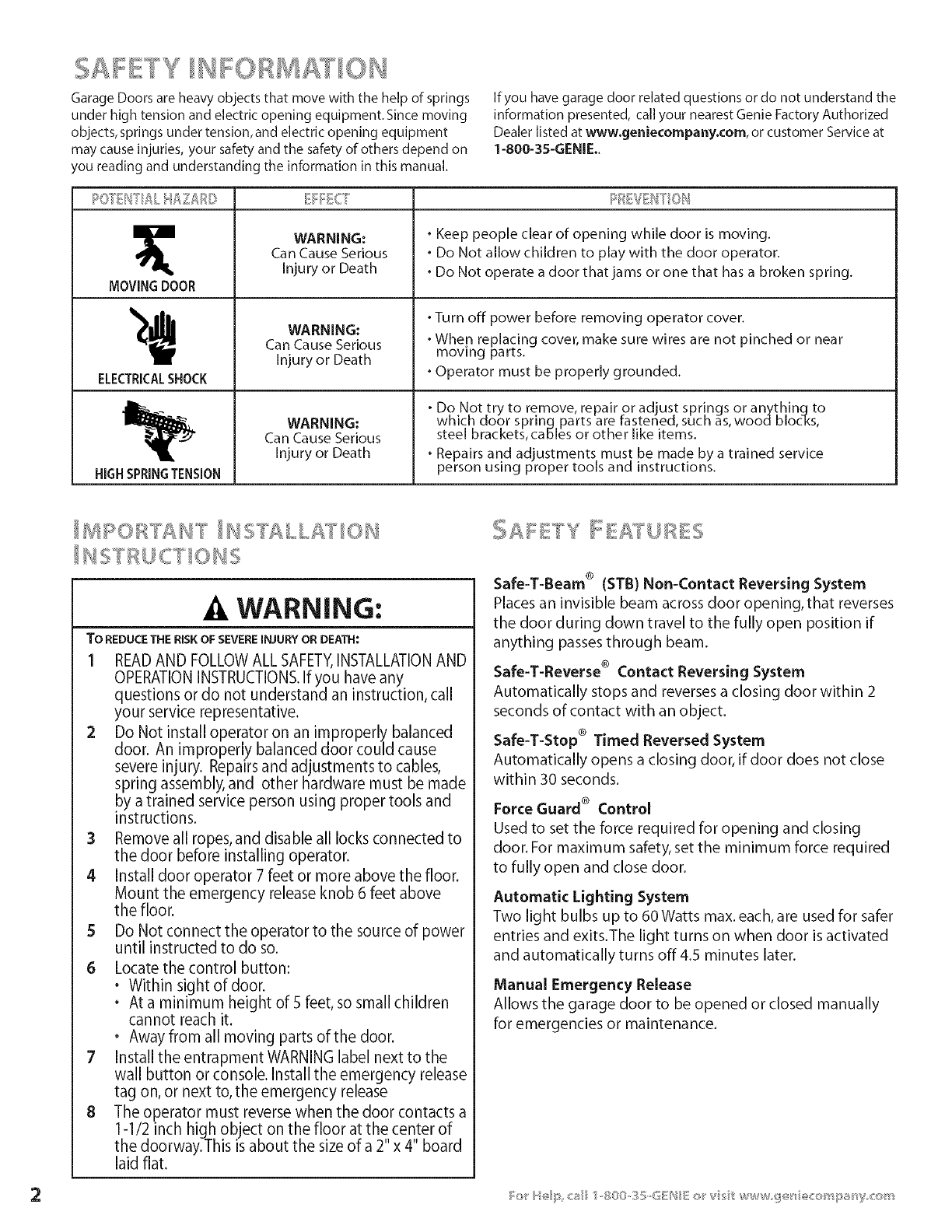
MOVINGDOOR
ELECTRICALSHOCK
HiGHSPRINGTENSION
EFFECT
WARNING:
Can Cause Serious
Injury or Death
WARNING:
Can Cause Serious
Injury or Death
WARNING:
Can Cause Serious
Injury or Death
•Keep people clear of opening while door is moving.
•Do Not allow children to play with the door operator.
•Do Not operate a door that jams or one that has a broken spring.
•Turn off power before removing operator cover.
•Whep replacing cover, make sure wires are not pinched or near
mowng parts.
•Operator must be properly grounded.
•Do Not try to remove, repair or adjust springs or anythinqto
which door sprinq parts are fastened, such as,wood blocks,
steel brackets, caNes or other like items.
•Repairs and adjustments must be made by a trained service
person using proper tools and instructions.
WARNING:
TO REDUCETHE RISKOF SEVEREINJURYOR DEATH:
1 READAND FOLLOW ALL SAFETY,INSTALLATIONAND
OPERATIONINSTRUCTIONS.If you have any
questions or do not understand an instruction, call
your service representative.
2 Do Not install operator on an improperly balanced
door. An improperly balanced door could cause
severe injury. Repairs and adjustments to cables,
spring assembly, and other hardware must be made
by a trained service person using proper tools and
instructions.
3Remove all ropes, and disable all locks connected to
the door before installing operator.
4 Install door operator 7 feet or more above the floor.
Mount the emergency release knob 6 feet above
the floor.
5 Do Not connect the operator to the source of power
until instructed to do so.
6 Locate the control button:
• Within sightofdoor.
• At a minimum height of 5 feet, so small children
cannot reach it.
• Away from all moving parts of the door.
7 Install the entrapment WARNING label next to the
wall button or console. Install the emergency release
tag on, or next to, the emergency release
8 The operator must reverse when the door contacts a
1-1/2 inch his h object on the floor at the center of
the doorway.This is about the size of a 2 x 4 board
laid flat.
Safe-T-Beam® (STB)Non-Contact ReversingSystem
Places an invisible beam across door opening, that reverses
the door during down travel to the fully open position if
anything passesthrough beam.
Safe-T-Reverse®ContactReversingSystem
Automatically stops and reverses a closing door within 2
seconds of contact with an object.
Safe-T-Stop®Timed Reversed System
Automatically opens a closing door, if door does not close
within 30 seconds.
Force Guard ®Control
Used to set the force required for opening and closing
door. For maximum safety, set the minimum force required
to fully open and close door.
Automatic Lighting System
Two light bulbs up to 60 Watts max. each, are used for safer
entries and exits.The light turns on when door isactivated
and automatically turns off 4.5 minutes later.
Manual Emergency Release
Allows the garage door to be opened or closed manually
for emergencies or maintenance.


