4
2.0 Wiring
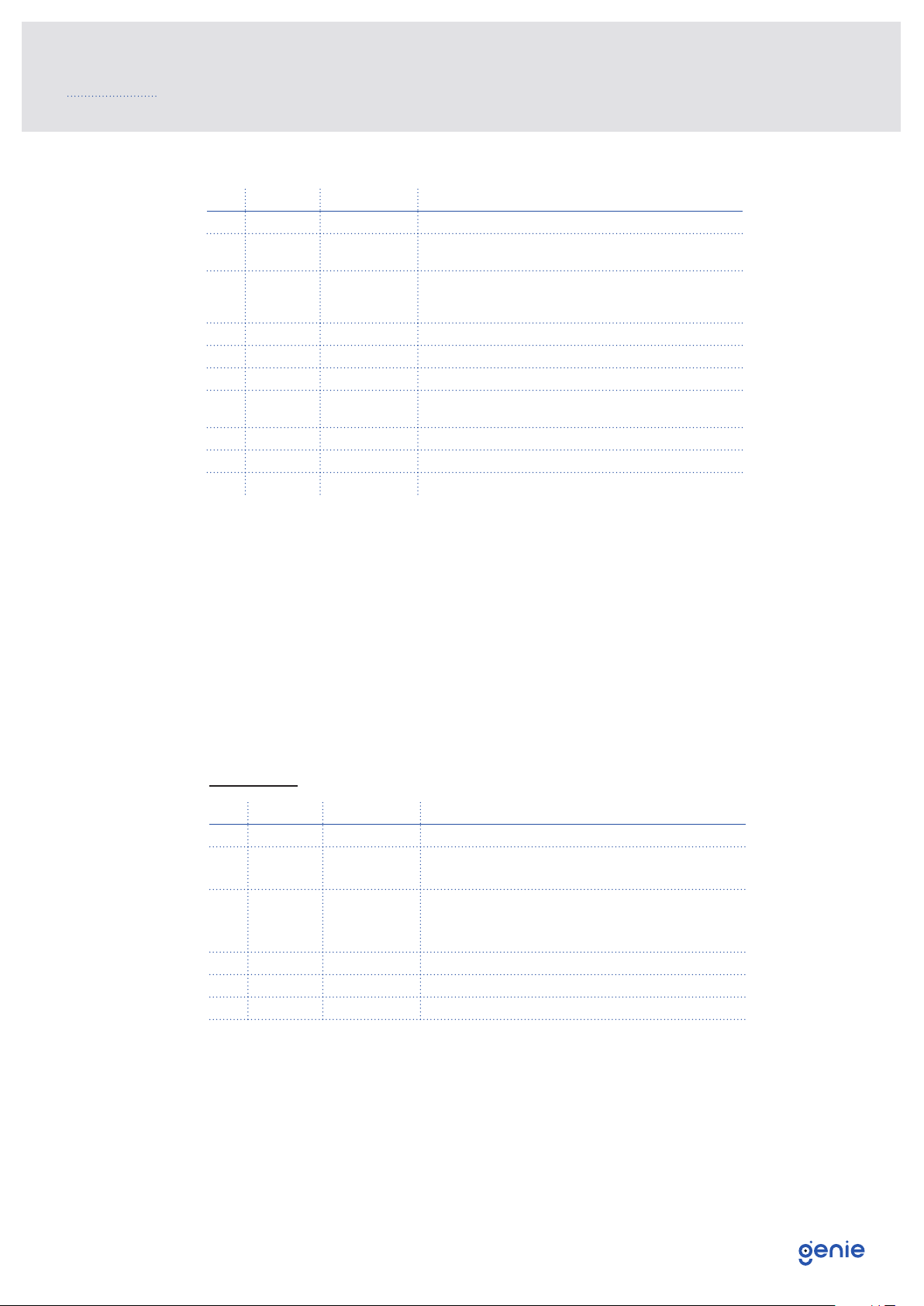
No. Colour Function Description
1Red VCC Power Supply: +7V~+15VDC
2Blue LED The LED indicator flashes when swiping
the card. Short to GND, LED will always on
3Yellow Buzzer
When swiping a card, the buzzer beeps
once. When shorted to GND, the buzzer
will always beep
4Green Data0 Data 0
5White Data1 Data 1
6Black GND GND
7Grey W26/34 SEL Disconnected: WG26 Output Shorted to GND is WG34
format
8Purple OUT Tamper output, available in low level
9Brown NC N /A
10 Orange NC N /A
No. Colour Function Description
1Black GND GND
3Blue LED The LED indicator flashes when swiping
the card. Short to GND, LED will always on.
4Yellow Buzzer
When swiping a card, the buzzer beeps
once. When shorted to GND, the buzzer
will always beep.
5Green Data0 (Data) Data 0
6White Data1 (Clock) Data 1
8Red VCC Power supply: +7V~+15VDC
Notes:
• The connection between the reader and controller should use 8 wires STP cable. The
diameter should be over 24 AWG (0.206mm). The distance should be less than 100M.
• To transmit the data successfully, the Data 0 and Data 1 should use the same pair, e.g.
Green and Green/white (pair of wires in the cable).
• When the transmitting distance is over 60M, the Data 0 and Data 1 wires should be
paralleled up with unused pairs to reduce the resistance. For example, if we have 4 free
wires, then 2 should be shortened to Data0 and 2 should be shortened to Data1.
• Do not use the same power supply source for the door lock and the reader to avoid
EMF (electromotive force) interference.
Wiegand 26