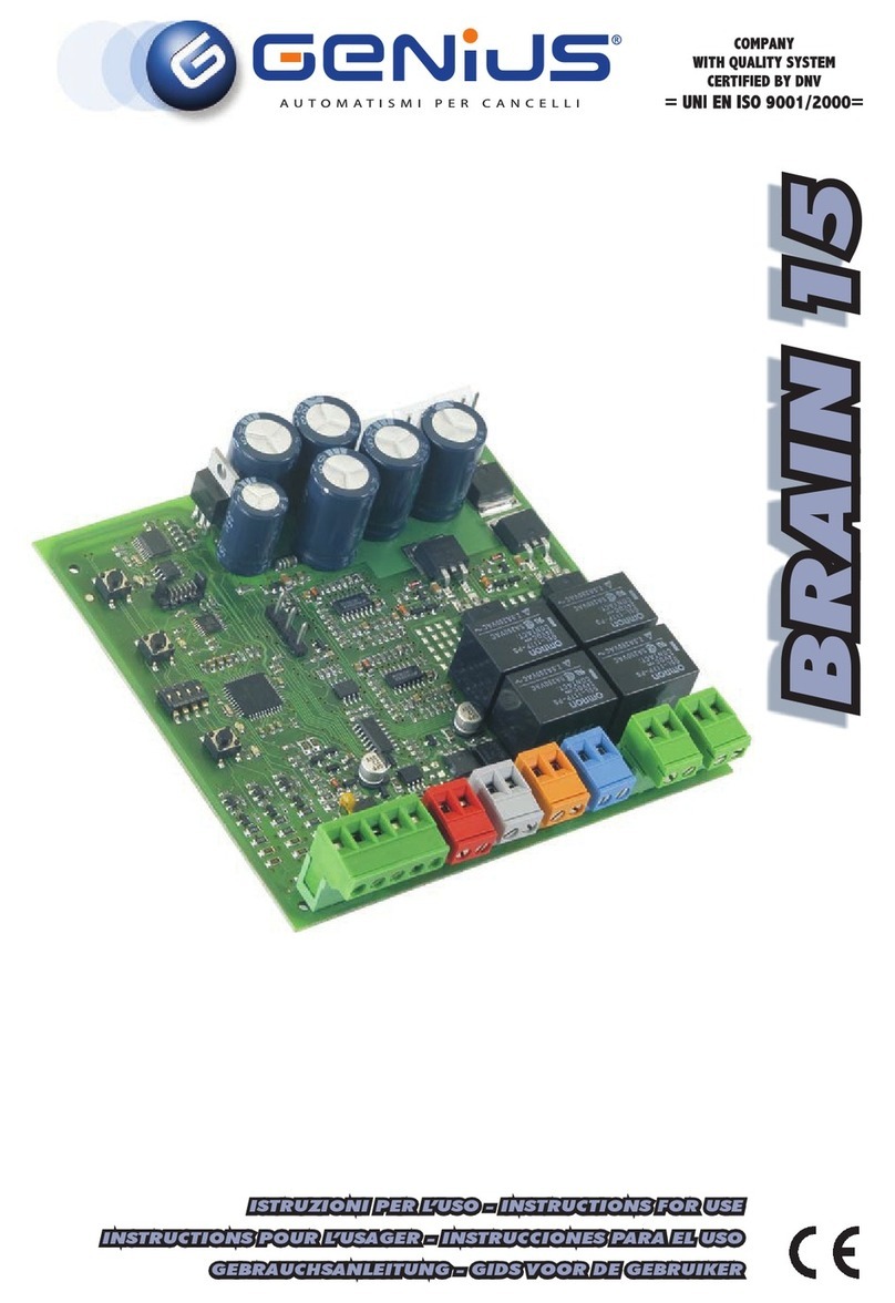
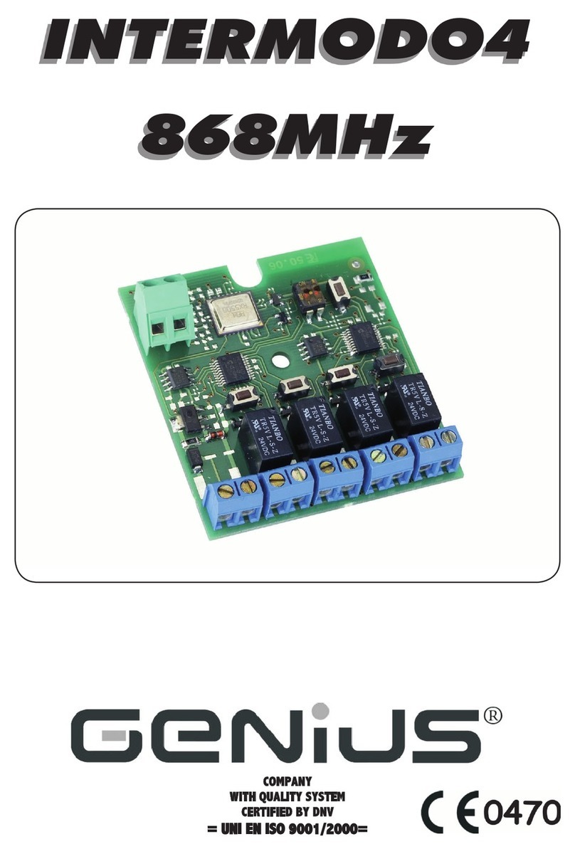
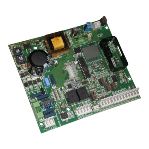
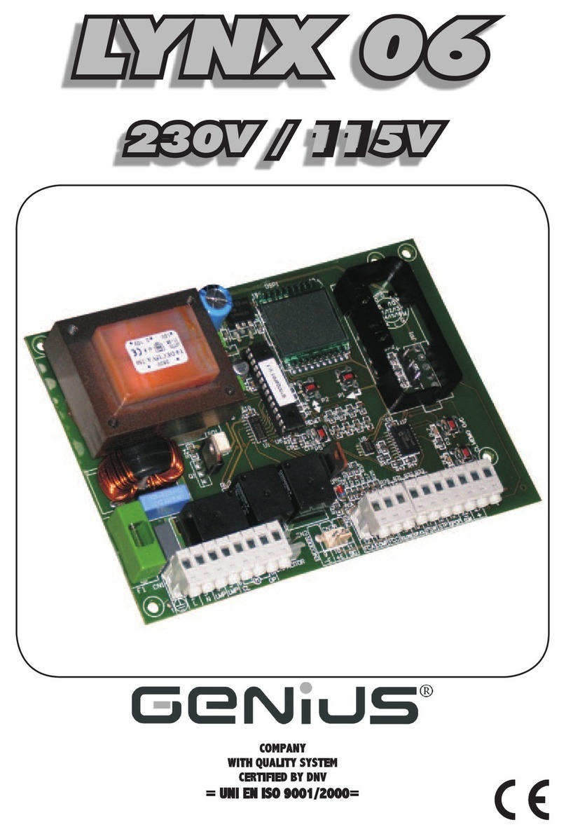
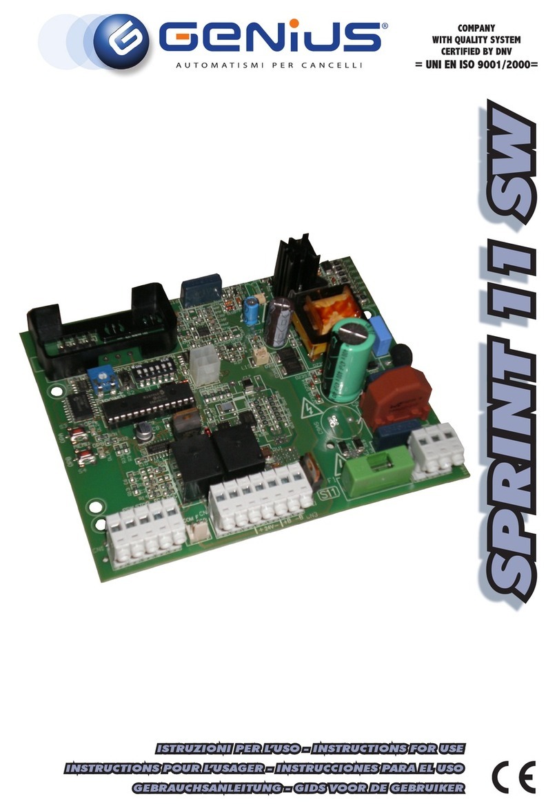
Genius JA388 Technical manual

JA388
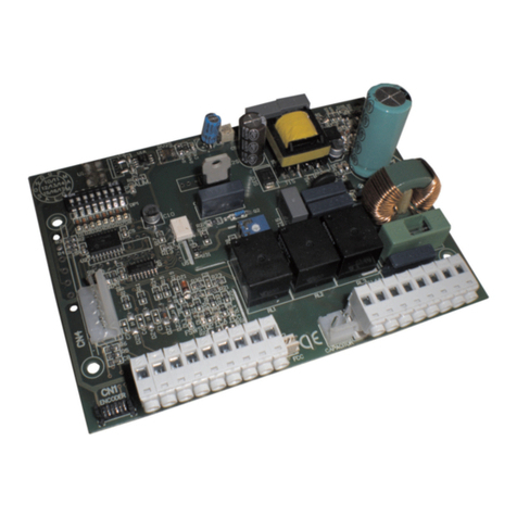
CONTROL BOARD FOR 115V HINGED GATES
EQUIPO ELECTRÓNICO PARA PORTONES DE TIPO BATIENTE 115V
USE AND INSTALLATION INSTRUCTIONS
INSTRUCCIONES PARA EL USO – NORMAS DE INSTALACIÓN

AVVERTENZEPERL’INSTALLATORE
OBBLIGHI GENERALI PER LA SICUREZZA
1) ATTENZIONE! È importante per la sicurezza delle persone seguire attenta-
mentetuttal’istruzione.Unaerratainstallazioneounerratousodelprodotto
può portare a gravi danni alle persone.
2) Leggere attentamente le istruzioniprimadiiniziarel’installazionedelprodot-
to.
3) I materiali dell’imballaggio (plastica, polistirolo, ecc.) non devono essere
lasciatiallaportatadeibambiniinquanto potenziali fonti di pericolo.
4) Conservare le istruzioni per riferimenti futuri.
5) Questo prodotto è stato progettato e costruito esclusivamente perl’utilizzo
indicatoin questadocumentazione. Qualsiasialtro utilizzononespressamen-
teindicato potrebbe pregiudicare l’integrità del prodotto e/o rappresen-
tare fonte di pericolo.
6) GENIUS declina qualsiasiresponsabilitàderivata dall’uso improprioo diverso
daquello per cui l’automatismo è destinato.
7) Noninstallare l’apparecchioinatmosfera esplosiva:la presenzadigas ofumi
infiammabilicostituisceungravepericoloperla sicurezza.
8) Gli elementi costruttivi meccanici devono essere in accordo con quanto
stabilito dalle Norme EN 12604 e EN 12605.
PeriPaesi extra-CEE, oltre ai riferimenti normativi nazionali, per ottenere un
livellodi sicurezza adeguato, devono essereseguitele Norme sopra riporta-
te.
9) GENIUS non è responsabile dell’inosservanza della BuonaTecnicanellaco-
struzione delle chiusure da motorizzare, nonché delle deformazioni che
dovesserointervenire nell’utilizzo.
10) L’installazionedeveessereeffettuata nell’osservanza delle NormeEN12453
eEN 12445. Il livello di sicurezza dell’automazione deve essere C+E.
11) Prima dieffettuarequalsiasi interventosull’impianto,togliere l’alimentazione
elettrica.
12) Prevedere sulla rete di alimentazione dell’automazione un interruttore
onnipolarecon distanza d’apertura dei contattiugualeo superiore a 3mm.
Èconsigliabilel’usodiunmagnetotermicoda6Aconinterruzioneonnipolare.
13) Verificare che a monte dell’impianto vi sia un interruttore differenzialecon
sogliada0,03A.
14) Verificare che l’impianto di terra sia realizzato a regola d’arte e collegarvi
lepartimetalliche della chiusura.
15) L’automazionedisponediuna sicurezza intrinseca antischiacciamento co-
stituitada uncontrollodi coppia. E'comunquenecessario verificarnelasogli
diinterventosecondo quanto previsto dalle Norme indicate al punto 10.
16) I dispositivi di sicurezza (norma EN 12978)permettono diproteggere even-
tuali aree di pericolo da Rischi meccanici di movimento, come ad Es.
schiacciamento,convogliamento,cesoiamento.
17) Perogniimpiantoè consigliato l’utilizzodialmeno una segnalazione lumino-
sanonché diun cartellodisegnalazione fissatoadeguatamentesulla struttu-
radell’infisso, oltre ai dispositivi citati al punto “16”.
18) GENIUSdeclinaogniresponsabilità aifinidella sicurezzaedel buon funziona-
mentodell’automazione, incaso venganoutilizzati componentidell’impian-
tonon di produzione GENIUS.
19) Perlamanutenzioneutilizzareesclusivamente parti originali GENIUS.
20) Non eseguire alcuna modifica sui componenti facenti parte del sistema
d’automazione.
21) L’installatore deve fornire tutte le informazioni relative al funzionamento
manuale del sistema in caso di emergenza e consegnare all’Utente
utilizzatoredell’impiantoil libretto d’avvertenze allegato al prodotto.
22) Nonpermettereaibambini o personedi sostare nellevicinanzedel prodotto
duranteil funzionamento.
23) Tenerefuoridallaportata deibambiniradiocomandi o qualsiasialtrodatore
diimpulso, per evitare che l’automazione possa essere azionata involonta-
riamente.
24) Iltransitotrale ante deve avvenire solo acancellocompletamenteaperto.
25) L’Utente utilizzatore deve astenersi da qualsiasi tentativo di riparazione o
d’interventodirettoerivolgersi solo a personale qualificato.
26) Tutto quello che non è previsto espressamente in queste istruzioni non è
permesso
IMPORTANT NOTICE FOR THE INSTALLER
GENERAL SAFETY REGULATIONS
1) ATTENTION! To ensure the safety of people, it is important that you read
all the following instructions. Incorrect installation or incorrect use of the
product could cause serious harm to people.
2) Carefully read the instructions before beginning toinstalltheproduct.
3) Do not leave packingmaterials (plastic, polystyrene, etc.) within reach of
childrenas such materials are potential sources of danger.
4) Storetheseinstructionsfor future reference.
5) This product was designed and built strictly for the use indicated in this
documentation.Any otheruse,not expressly indicatedhere, could compro-
mise the good condition/operation of the product and/or be a source of
danger.
6) GENIUS declines all liabilitycausedbyimproper use or useotherthan that for
whichthe automatedsystem wasintended.
7) Do not install the equipment in an explosive atmosphere: the presence of
inflammablegas or fumes is a serious danger tosafety.
8) The mechanical parts must conform to the provisionsofStandardsEN12604
andEN 12605.
For non-EU countries, to obtain an adequate level of safety, the Standards
mentionedabovemustbeobserved, inaddition tonational legalregulations.
9) GENIUS is not responsible for failure to observe Good Technique in the
constructionof the closingelementsto be motorised, orforany deformation
thatmay occur duringuse.
10) Theinstallationmustconform toStandardsEN 12453andEN 12445.Thesafety
levelof the automated system mustbeC+E.
11) Before attempting any job on the system, cut out electrical power.
12) Themains power supply of the automated systemmustbefittedwithan all-
pole switch with contact opening distance of 3mm or greater. Use of a 6A
thermalbreakerwith all-pole circuit break is recommended.
13) Makesurethata differential switch with threshold of 0.03Aisfitted upstream
ofthe system.
14) Make sure that the earthing system is perfectly constructed, and connect
metalparts of the means of the closure to it.
15) The automatedsystem is suppliedwith anintrinsicanti-crushing safetydevice
consisting of a torque control. Nevertheless, its tripping threshold must be
checkedas specified in the Standards indicated at point 10.
16) The safety devices (EN 12978 standard) protect any danger areas against
mechanicalmovement Risks,suchas crushing, dragging,and shearing.
17) Use of at least one indicator-light is recommended for every system, as well
asawarningsignadequately secured to the frame structure, in addition to
thedevices mentioned at point “16”.
18) GENIUSdeclinesallliability as concerns safety and efficientoperationof the
automatedsystem,ifsystem componentsnot producedby GENIUSareused.
19) Formaintenance,strictlyuse original parts by GENIUS.
20) Donotinany way modify the componentsofthe automated system.
21) Theinstallershallsupply all information concerning manual operationofthe
systemin caseof anemergency,and shallhandover tothe user thewarnings
handbooksupplied withtheproduct.
22) Do not allow children or adults to stay near the product while it is operating.
23) Keep remote controls or other pulse generators away from children, to
preventthe automated system frombeingactivatedinvoluntarily.
24) Transitthroughtheleaves is allowed only when the gate is fully open.
25) The user must not attempt any kindof repairor directaction whatever and
contactqualified personnel only.
26) Anything not expressly specified in these instructions is not permitted.
CONSIGNES POUR L'INSTALLATEUR
RÈGLES DE SÉCURITÉ
1) ATTENTION! Il est important, pour la sécurité des personnes, de suivre à la
lettre toutes les instructions. Une installation erronée ou un usage erroné
du produit peut entraîner de graves conséquences pour les personnes.
2) Lire attentivement les instructions avant d'installer le produit.
3) Lesmatériaux d'emballage(matièreplastique, polystyrène,etc.)ne doivent
pas être laissés à la portée des enfants car ils constituent des sources
potentiellesde danger.
4) Conserver les instructions pour lesréférencesfutures.
5) Ce produit aétéconçu et construitexclusivement pour l'usageindiquédans
cette documentation. Toute autre utilisation non expressément indiquée
pourraitcompromettre l'intégrité du produit et/ou représenter une source
dedanger.
6) GENIUS décline toute responsabilité qui dériverait d'usage impropre ou
différentde celui auquel l'automatisme est destiné.
7) Ne pas installer l'appareil dans une atmosphère explosive: la présence de
gazou de fumées inflammablesconstitueungrave danger pour lasécurité.
8) Lescomposants mécaniquesdoivent répondreaux prescriptionsdes Normes
EN 12604 et EN 12605.
Pourles Pays extra-CEE, l'obtention d'un niveau desécuritéapproprié exige
nonseulement le respectdes normes nationales,maiségalement le respect
desNormessusmentionnées.
9) GENIUSn'est pasresponsabledu non-respectdela BonneTechniquedans la
constructiondes fermetures à motoriser, ni des déformations qui pourraient
intervenirlorsde l'utilisation.
10) L'installationdoitêtreeffectuée conformément aux Normes EN 12453 et EN
12445.Leniveaude sécurité de l'automatisme doit être C+E.
11) Couperl'alimentationélectriqueavant toute intervention sur l'installation.
12) Prévoir, sur le secteur d'alimentation de l'automatisme, un interrupteur
omnipolaireavecune distanced'ouverturedescontactségale ousupérieure
à 3 mm. On recommande d'utiliser un magnétothermique de 6A avec
interruptionomnipolaire.
13) Vérifierqu'ilyait,enamont de l'installation, un interrupteur différentiel avec
unseuilde 0,03 A.
14) Vérifier que la mise à terre est réalisée selon les règles de l'art et y connecter
lespiècesmétalliques de la fermeture.
15) L'automatismedisposed'unesécurité intrinsèque anti-écrasement, formée
d'un contrôle du couple. Il est toutefois nécessaire d'en vérifier le seuil
d'interventionsuivant les prescriptions des Normes indiquéesaupoint 10.
16) Les dispositifs de sécurité (norme EN 12978) permettent de protéger des
zones éventuellement dangereuses contre les Risques mécaniques du
mouvement,commel'écrasement,l'acheminement, le cisaillement.
1
ENGLISH
230 VAC
50 Hz
24 Vdc
3 W
J4 J1
J3
PE N L
MAIN
12 45678
COM OP
M1 COM OP
M2 CL
LA M P
9 10111213141516 171819
OPEN
AB
STP
CL OP
FSW
---
+24V
++
-TX
FSW
20 21
W.L.
LO C K
J5
3
230 VAC
max.60W
12 V ac
J6
22
23
24 25
FC A 1
FC C 1
FC A 2
FC C 2
C1
M1
C2
M2
3. LAYOUT AND COMPONENTS
Fig. 1
NB.: Capacitors are supplied with the operators. Fig. 2
J4 J1
J3
F1
F2
1234
910111256781234
PE N L
MAIN
12 45678
COM OP
M1 COM OP
M2 CL
LA M P
9 10111213141516171819
OPEN
AB
STP
CL OP
FSW
---
+24V
++
-TX
FSW
J2
F
DL10
OP_A OP_B
STOP FSWOPFSWCL
20 21
W.L.
LO C K
J5
22
23
24 25
FC A 1
FC C 1
FC A 2
FC C 2
J6
FCA2FCA1
FCC2FCC1
TOTALLYOPEN
OPEN LEAF 1
STOP
1. WARNINGS
Important: Before attempting any work on the control board
(connections, maintenance), always turn off power.
- Install, upstream of the system, a differential thermal breaker
(Residual Current Device) with adequate tripping threshold.
- Connectthe earth cabletothe appropriateterminalon theJ3
connector of the equipment (see fig.2).
- Alwaysseparatepowercables fromcontrol andsafety cables
(push-button, receiver,photocells,etc.).Toavoidanyelectric
noise,use separate sheathsora shieldedcable(with earthed
shield).
CONTROL BOARD JA388
4. ELECTRIC CONNECTIONS
F1
F2
J1
J3 J4 J5 J6
LIMIT-SWITCH
2. TECHNICAL SPECIFICATIONS
Power supply 115 V~ ( +6% -10%) - 50 Hz
Absorbed power 10 W
Motor max. load 1200 W
Accessories max. load 0,5 A
Electric lock max. load 15 VA
Operating ambient temperature -20 °C +55 °C
Protection fuses 2 (see fig. 1)
Function logics Automatic / Semi-automatic / "Stepped" safety devices /
Semi-automatic B / Dead-man C / "Stepped" semi-automatic
Opening/closing time Programmable (from 0 to 120 s)
Pause time 0, 10, 20, 30, 60, 120 s
Closing leaf delay
0, 5, 10, 20 s
Opening leaf delay 2 s (Can be disabled with the dip-switch)
Thrust force Dip-switch adjustable on 8 levels for each motor
Terminal board inputs Open / Open free leaf / Stop / Limit-switch
Opening safety devices / Closing safety devices / Power supply + Earth
Terminal board outputs Flashing lamp - Motors - 24 Vdc accessories power
supply- 24 Vdc indicator-light - Fail safe - 12 Vac electric
lock power supply
Rapid connector Rapid connector 5 pins
Selectable functions Logics and pause times - Thrust force -
Opening and closing leaf delay - Reversing stroke -
Fail safe - Closing safety devices logic - Pre-flashing
Programming key
Simple
or
Advanced
work time learning,
with or without Limit-switch and/or encoder
For connection of
thephotocells
andsafety
devices,see
paragraph4.1.
BLUE
BLUE
F
J2
Led
DL10
DS1 DS2
LedOP_A TOTALLYOPENLED
Led OP_B LED: OPEN LEAF 1 / CLOSE
Led STOP LED STOP
Led FSWCL LED: CLOSING SAFETY DEVICES
Led FSWOP LED: OPENING SAFETY DEVICES
LedFCA1 LED:LEAF 1 OPENINGLIMIT-SWITCH
LedFCC1 LED: LEAF1 CLOSINGLIMIT-SWITCH
LedFCA2 LED:LEAF 2 OPENINGLIMIT-SWITCH
LedFCC2 LED: LEAF2 CLOSINGLIMIT-SWITCH
DL10 LED:TIMELEARNING SIGNALLING
J1 LOWVOLTAGETERMINAL BOARD
J2 RAPID CONNECTOR 5 PINS
J3 230 VAC POWER SUPPLY TERMINAL BOARD
J4 MOTORS AND FLASHING LAMP CONNECTION TERMINAL BOARD
J5 INDICATOR-LIGHT AND ELECTRIC LOCK TERMINAL BOARD
J6 LIMIT-SWITCH AND ENCODER TERMINAL BOARD
F1 MOTORS AND TRANSFORMER PRIMARY WINDING FUSE (F 5A)
F2 LOW VOLTAGE AND ACCESSORIES FUSE (T 800mA)
FTIME LEARNING SELECTION PUSH-BUTTON
DS1 1ST GROUP OF MICROSWITCH PROGRAMMING
DS2 2ND GROUP OF MICROSWITCH PROGRAMMING

2
ENGLISH
4.1. Connection of photocells and safety devices
Before connecting the photocells (or other devices) we advise
youto select thetype ofoperationaccording tothe movement
area they have to protect (see fig.3):
Opening safety devices:
they operate only during the gate
openingmovementand,therefore,theyaresuitablefor
protectingthe area between theopening leaves and
fixed obstacles (walls, etc) against the risk of impact
and crushing.
Closingsafetydevices:
theyoperate onlyduringthe gateclosing
movement and, therefore, they are suitable for
protecting the closing area against the risk of impact.
Opening/closingsafety devices
Closingsafety devices Opening
safetydevices
1
2
5
4
3
1
2
RX CL TX CL
1
2
5
4
3
1
2
RX OP/CL
TX OP/CL
-
+
-
+
1
2
5
4
3
1
2
RX OP TX OP
-
+
-
+
9 10111213141516171819
OPEN
AB
STP
CL OP
FSW
---
+24V
++
-TX
FSW
20 21
W.L.
LO C K
Connection of a pair of closing photocells and a pair of
opening/closing photocells (recommended lay-out)
9 10111213141516171819
OPEN
AB
STP
CL OP
FSW
---
+24V
++
-TX
FSW
20 21
W.L.
LO C K
1
2
5
4
3
1
2
RX CL TX CL
1
2
5
4
3
1
2
RX OP/CL
TX OP/CL
-
+
-
+
Fig. 3
Opening/closing safety devices:
they operate during the gate
openingandclosing movements and,therefore, they
aresuitablefor the openingand closing areas against
the risk of impact.
It is recommends use of the lay-out in fig. 4 (in the event of fixed
obstacles at opening) or in fig. 5 (no fixed obstacles).
N.B. If two or more devices have the same function (opening or
closing), they should be connected to each other in series (see
fig. 12). N.C. contacts must be used.
Connection of a closing safety device and an opening
safety device
9 10111213141516171819
OPEN
AB
STP
CL OP
FSW
---
+24V
++
-TX
FSW
20 21
W.L.
LO C K
Fig. 6
Connection of a pair of closing photocells, a pair of
opening photocells and a pair of opening/closing
photocells (recommended lay-out)
Fig. 4
Connection of no safety device
9 10111213141516171819
OPEN
AB
STP
CL OP
FSW
---
+24V
++
-TX
FSW
20 21
W.L.
LO C K
Fig. 7
Fig. 5
Connection of 1 pair of opening photocells
1
2
5
4
3
1
2
RX TX
-
+
-
+
9 10111213141516171819
OPEN
AB
STP
CL OP
FSW
---
+24V
++
-TX
FSW
20 21
W.L.
LO C K
Fig. 8

3
ENGLISH
Connection of a pair of opening photocells and a pair of
closing photocells
1
2
5
4
3
1
2
RX CL
TX CL
1
2
5
4
3
1
2
RX OP TX OP
-
-
-
-
+
+
+
+
9 10111213141516171819
OPEN
AB
STP
CL OP
FSW
---
+24V
++
-TX
FSW
20 21
W.L.
LO C K
9 10111213141516171819
OPEN
AB
STP
CL OP
FSW
---
+24V
++
-TX
FSW
20 21
W.L.
LO C K
1
2
5
4
3
1
2
RX CL1 TX CL1
1
2
5
4
3
1
2
RX CL2
TX CL2
-
+
-
+
Fig. 11
Connection of two pairs of closing photocells
Fig. 10
1
2
5
4
3
1
2
RX TX
-
+
-
+
9 10111213141516171819
OPEN
AB
STP
CL OP
FSW
---
+24V
++
-TX
FSW
20 21
W.L.
LO C K
Fig. 9
Connection of 1 pair of closing photocells
Fig. 12
Fig. 13
Connection of 2 N.C. contacts in series
(e.g. Photocells, Stop)
Connection of 2 N.O. contacts in parallel
(e.g. Open A, Open B)
4.2. Terminal board J3 - Power supply (fig. 2)
PE: Earth connection
N:230 V~ power supply ( Neutral )
L:230 V~ power supply ( Line )
NB.:For correctoperation, theboardmust beconnected tothe
earthconductorin the system.Install an adequate differential
thermal breaker (RCD) upstream of the system.
4.3. Terminal board J4 - Motors and flashing lamp (fig. 2)
M1 : Terminals 1/2/3 = COM/OP/CL: Connection to Motor 1
Can be used in the single-leaf application
M2 : Terminals 4/5/6 = COM/OP/CL: Connection to Motor 2
Cannot be used in the single-leaf application
LAMP : Terminals 7/8 = Flashing lamp output ( 230 V ~)
4.4. Terminal board J1 - Accessories (fig. 2)
OPEN A - Terminal 9 plus a negative = "Total Opening"
command (N.O.): any pulse generator (push-button,
detector,etc.) which,by closinga contact,commands
opening and/or closing of both gate leaves.
Toinstall several fullopening pulsegenerators, connect
the N.O. contacts in parallel (see fig.13).
OPEN B - Terminal 10 plus a negative = "Partial Opening"
command(N.O.)/ Closing: any pulsegenerator (push-
button, detector, etc.) which, by closing a contact,
commandsopening and/orclosingof theleaf drivenby
motor M1. In the Band Clogics, it always commands
closingof both leaves.
To install several partial opening pulse generators,
connect the N.O. contacts in parallel (see fig.13).
STP - Terminal11 plusa negative= STOPcontact (N.C.): any
device (e.g. a push-button) which, by opening a
contact, is able to stop gate movement.
ToinstallseveralSTOPdevices,connectthe N.C.contacts
inseries (seefig.12).
NB.:If STOPdevicesarenotconnected, jumperconnect
the STP terminals and - common.
CLFSW-Terminal12plusanegative = Closingsafetydevices
contact(N.C.): Thepurpose oftheclosing safetydevices
are to protect the leaf movement area during closing.
Duringclosing, intheA-SP-E-EPlogics,thesafety devices
reverse the movement of the gate leaves, or stop and
reverse the movement when they are released (see
programmingofmicroswitchDS2-SW2).Duringtheclosing
cycle in logics Band C, they interrupt movement. They
never operate during the opening cycle. If the closing
safety devices operate when the gate is open, they
preventthe leafclosing movement.
NB.: If no closing safety devices are connected, jumper
connect terminals CL and -TX FSW (fig. 7).

4
ENGLISH
OPFSW-
Terminal13plusanegative=
Openingsafetydevices
contact(N.C.): The purposeof theopening safetydevices
are to protect the leaf movement area during opening.
Duringopening,intheA-SP-E-EPlogics, the safetydevices
stop the movement of the gate leaves and reverse the
movement when they are released. During the opening
cycle in logics Band C, they interrupt movement. They
never operate during the closing cycle.
Iftheopeningsafetydevicesoperatewhenthegateisclosed,
theypreventtheleafopeningmovement.
NB.: If no opening safety devices are connected, jumper
connect inputs OP and -TX FSW (fig. 7).
–- Terminal 14/15/16 = Negative for power supply to
accessories, are all negative.
+- Terminal 17/18 = 24 Vdc - Positive for power supply to
accessories, are all positive.
Important:Accessories max.loadis 500mA.To calculate
absorptionvalues, refer to theinstructions for individual
accessories.
-TXFSW- Terminal19=Negativeforpowersupplytophotocell
transmitters.
If you use this terminal for connecting the negative for
supplyingpower tothe photocelltransmitters, youmay,
if necessary, also use the FAIL SAFE function (see
programmingof microswitchDS2 -SW3).
If this function is enabled, the equipment checks
operation of the photocells before every opening or
closingcycle.
4.5.
TerminalboardJ5-Indicator-lightandElectriclock(fig.2)
W.L. - Terminal 20 = Power supply to indicator-light
Connecta 24 Vdc- 3 Wmax. indicator-light, ifrequired,
between this terminal and the +24V supply. To avoid
compromising correct operation of the system, do not
exceed the indicated power.
LOCK - Terminal 21 = Power supply to electric lock
If required/necessary, connect a 12 V ac electric lock
between terminal 21 and the terminal 18 the +24V
supply.
4.6. Connector J2 - Rapid connector 5 pins
This is used for rapid connection. Connect the accessory, with
the components side facing the inside of the card. Insert and
removeonly after switchingoff power.
RP
JA592
Fig. 16
4.7.
Terminal board J6 - Limit-switches and/or encoder(fig.2)
Theseinputsaredesignedforconnectionofopeningandclosing
limit-switches which, according to type of programming - can
commandeitherleafstoporstartofdeceleration.Unconnected
limit-switchesmustbejumperconnected(ifnoneareconnected,
thisis not necessary).
Encoders can also be used to detect the leaf's angular position
andtothusobtaindecelerationandstoppositionsindependent
ofwork time.
Limit-switchesandencoderscanalsobe usedin combinationto
stopmovement beforethe mechanicalstoplimit isreached. To
wire, see fig. 17a, 17b and 17c.
FCA1 - Leaf 1 opening limit-switch
FCC1 - Leaf 1 closing limit-switch
FCA2 - Leaf 2 opening limit-switch
FCC2 - Leaf 2 closing limit-switch
N.B.: Maximum configurations are shown on the drawings. All
intermediateconfigurations areallowed,using onlysome
elements (only 1 encoder, only 1 limit-switch, 2 encoders
and 2 limit-switches etc.).
14 15 16 17 18 19
---
+24V
++
-TX
FSW
20 21
W.L.
LO C K
J5 J6
22
23
24 25
FC A 1
FC C 1
FC A 2
FC C 2
Fig. 17b
Fig. 17c
Fig. 17a
RED
RED
BLACK
BLACK
WHITE
WHITE
RED
RED
BLACK
BLACK
WHITE
WHITE
Encoder 1
Encoder 2
Encoder 2
Encoder 1

5
ENGLISH
The equipment is endowed with two groups of microswitches -
DS1(fig. 18) andDS2 (fig.19) -whichmake it possibleto program
the gate operation parameters.
5.1. MICROSWITCHES DS1 (fig. 18)
Leaf 1 and 2 force
By using microswitches SW1, SW2 and SW3, the force (and thus
anti-crushingsafety) ofthe operatorconnected toleaf 1 canbe
programmed. The same operation has to be repeated on the
motorconnected toleaf2, byusingmicroswitches SW4,SW5 and
SW6.
Functionlogic
The automated system's function logic can be selected with
microswitchesSW7,SW8,SW9andSW10. Byselectinganautomatic
logic(A,SP), thecombinationof microswitchesenablesselection
of pause time too (waiting time, in opening position, before
automaticre-closing).
The available logics - their operation is described in tables 3/a-
b-c-d-e-f, are as follows: A - SP (Automatic), E - EP - B (Semi-
automatic), C (Dead-man).
Closing leaf delay
Programmingof microswitchesSW11and SW12enables delayof
the closing start of leaf 1 with respect to leaf 2, in order to avoid
theleaves overlappingduring movement,andthus increasethe
safety of the system.
5. MICROSWITCH PROGRAMMING
Fail safe
Programmingthe microswitch SW3makes itpossible to activate
orde-activatethe photocellscontroltest. WhenFailsafeis active,
the equipment checks the photocells before every opening or
closingmovement.
Reversing stroke + over-pushing stroke
By using the microswitch SW4, you can activate the "reversing
stroke"andthe "over-pushingstroke".The"reversing stroke"pushes
theleaves to closefor a fewmoments beforeopeningthe gate,
thus facilitating release of the electric lock. The "over-pushing
stroke"commands aclosing thrustatfull forcewhen thegate has
alreadyreachedits stop limit, thusfacilitating the locking ofthe
electriclock.
123 4
2
SW 1
0
ON
OFF
SW 2
ON
OFF
SW 3
ON
OFF
SW 4
ON
OFF
OPENING LEAF DELAY (s)
CLOSINGPHOTOCELLLOGIC
REVERSESIMMEDIATELY
REVERSESONRELEASE
FAILSAFE
YES
NO
REVERSING STROKE
+ OVER-PUSHING STROKE
NO
YES
Fig. 19
Fig. 18
SW12
ON
OFF
1 (MIN)
2
3
4
SW1
ON
OFF
ON
OFF
SW2
ON
ON
OFF
OFF
5
6
ON
ONOFF
ON
SW3
ON
ON
ON
ON
OFF
OFF
7OFFON OFF
8 (MAX) OFFOFF OFF
123 45678 910 11 12
1 (MIN)
2
3
4
SW4
ON
OFF
ON
OFF
SW5
ON
ON
OFF
OFF
5
6
ON
ONOFF
ON
SW6
ON
ON
ON
ON
OFF
OFF
7OFF
ON OFF
8 (MAX) OFF
OFF OFF
E
SW7
ON
SW8
ON
A
A
ON
ON
OFF
ON
SW9
ON
OFF
OFF
AOFF
ON OFF
AOFF
OFF OFF
SW10
A
A
SP
SP
ON
OFF
ON
OFF
ON
ON
OFF
OFF
SP
SP
ON
ON
OFF
ON
ON
ON
ON
ON
OFF
OFF
SP OFFON OFF
SP OFF
OFF OFF
ON
ON
ON
ON
ON
OFF
OFF
OFF
OFF
OFF
OFF
OFF
OFF
/
0
10
20
30
60
120
0
10
20
30
60
120
SW11
ON
OFF
OFF
OFF
ON
ON
20
0
10
5
EP
B
C
OFF
ON
OFF
ON
OFF
OFF
ON
ON
ON
ON
ON
ON
/
/
/
DS1
DS2
LEAF 1 FORCE LEAF 2 FORCE
LOGIC PAUSE (s)
CLOSINGLEAF
DELAY (s)
6. START-UP
6.1. LEDCHECK
The table below shows the status of the LEDs in relation to to the
status of the inputs.
Notethe following:
L
ED
LIGHTED
= closed contact
L
ED
OFF
= open contact
Check the state of the LEDs as per Table.
Operation of the status signalling LEDs
LEDs LIGHTED OFF
OP_A Command activated Comando inattivo
OP_B Command activated Comando inattivo
STOP Command inactive Command activated
FSWCL Safety devices disengaged Safety devices engaged
FSWOP Safety devices disengaged Safety devices engaged
FCA1 (if used) Limit-switch free Limit-switch engaged
FCC1 (if used) Limit-switch free Limit-switch engaged
FCC2 (if used) Limit-switch free Limit-switch engaged
FCA2 (if used) Limit-switch free Limit-switch engaged
DL10
Gateclosed atrest:
OFF
Gatemovingoron
pause:
likeindicator-light
Timelearning:
flashesrapidly
NB.: The status of the LEDs while the gate is at rest are shown in
bold.
Furthermore, the DL10 LED is on the board and functions as
detailed in the following table:
5.2. MICROSWITCHES DS2 (fig. 19)
Openingleafdelay
Programmingof microswitch SW1enables delayof the opening
start of leaf 2 with respect to leaf 1, in order to avoid the leaves
obstructing each other during the initial stage of movement.
Closing photocells logic
Byusingmicroswitch SW2, youcan select the typeof behaviour
of the automated system if the photocells protecting the gate
closingmovementareengaged.Youcanobtaineitherimmediate
reversing of the leaves or a stop followed by reversing when the
photocellsare disengaged.

6
ENGLISH
Opening/closing time is established by a learning procedure
which varies slightly according to whether you are using limit-
switches.
6.3.1.LEARNINGOF NORMALTIMES
- SIMPLE LEARNING:
Check if the leaves are closed, and then press F push-button for
one second: DL10 LED begins flashing and the leaves begin the
opening movement.
Wait for the leaf to reach the opening stop limit and then supply
an OPEN A pulse (with the radio control or with the key controlled
push-button) to stop the movement: the leaves stop and the
DL10 LED stops flashing.
The procedure has ended and the gate is ready to operate.
Next pulse closes leaves and they stop on automaticaly reaching
closed position.
- ADVANCED COMPLETE LEARNING:
Check if the leaves are closed, and then press F push-button for
more than 3 seconds: DL10 LED begins flashing and the leaf 1
begins the opening movement. The following functions can be
commanded by the OPEN A pulses (by radio control or key
controlled push-button):
1° OPEN - Deceleration at opening of leaf 1
2° OPEN - Leaf 1 stops at opening and leaf 2 begins its
opening movement
3° OPEN - Deceleration at opening of leaf 2
4° OPEN - Leaf 2 stops at opening and immediately begins
its closing movement
5° OPEN - Deceleration at closing of leaf 2
6° OPEN - Leaf 2 stops at closing and leaf 1 begins its closing
movement
7° OPEN - Deceleration at closing of leaf 1
8° OPEN - Leaf 1 stops at closing
The DL10 LED stops flashing and the gate is ready for normal
operation.
Notes: •If you wish to eliminate deceleration in certain stages,
wait for the leaf to reach its stop-limit and supply 2
consecutive Open pulses (by 1 second).
•If only one leaf is present, the entire sequence must
nevertheless be effected. When the leaf has finished
opening, supply 5 Open pulses until the leaf begins to
close, and then resume normal operation.
•It wind effected areas it is best to allow 2 second after
the leaf reaches open stop befor supplying Open A to
ensure full closing.
WARNING:duringthelearningprocedure, the safetydevicesare
disabled! Therefore any transit must be avoided in the leaf
movement area when this operation is carried out.
6.2. ROTATION DIRECTION AND FORCE CHECK
1) Program the functions of the control board according to
need, as shown in Chapter 5.
2) Cut power to the electronic control equipment.
3) Release the operators and manually move the gate to the
mid-point of the opening angle.
4) Re-lock the operators.
5) Restore power.
6) Send and opening command on the OPEN A input (fig.2)
and check if the gate leaves are being commanded to
open.
N.B.:If the first OPEN A pulse commands a closing, cut power and
change over the phases of the electric motor (brown and
black wires) on the terminal board.
7) Check power setting of the motors and, if necessary, modify
it (see Chapter 5.1).
N.B.:If using hydraulic operators, force should be programmed to
maximum level (8)
8) Stop leaf movement with a STOP command.
9) Release the operators, close the leaves and re-lock the
operators.
6.3. LEARNING OF OPERATING TIMES
6.3.2.LEARNINGWITH LIMIT-SWITCHES
Learning with limit-switches can be done in two different ways:
- SIMPLE LEARNING:
Check if the leaves are closed, and then press F push-button for
1 second: DL10 LED begins flashing and the leaves begin the
openingmovement.
The motors stop automatically when the opening limit-switches
are reached, but an OPEN A pulse must be given (by radio
controlor keypush-button) toend thecycle;the leavesstop and
the DL10 LED stops flashing.
The procedure has ended and the gate is ready to operate.
Nextpulsecloses leavesandthey stoponautomaticalyreaching
closedposition.
- ADVANCED COMPLETE LEARNING:
Checkif the leavesare closed,andthen pressthe F push-button
for more than 3 seconds: DL10 LED begins flashing and leaf 1
begins the opening movement. The leaves automatically
deceleratewhen they reachthe limit-switches,and therefore, it
issufficienttoinformthe equipmentthatthe stoplimitshave been
reachedbymeans ofOPENApulses (byradiocontrol orkeypush-
button):
FCA1 - Deceleration at opening of leaf 1
1° OPEN - Leaf 1 stops at opening and leaf 2 begins its
openingmovement
FCA2 - Deceleration at opening of leaf 2
2° OPEN - Leaf 2 stops at opening and immediately begins
itsclosing movement
FCC2 - Deceleration at closing of leaf 2
3° OPEN - Leaf 2 stops at closing and leaf 1 begins its closing
movement
FCC1 - Deceleration at closing of leaf 1
4° OPEN - Leaf 1 stops at closing
the DL10 LED stops flashing and the gate is ready for normal
operation
Notes: •If you wish to eliminate deceleration in some stages,
you must supply an Open pulse within 1 second of
reachingthe limit-switch.
•If some limit-switches are not installed, start the
corresponding deceleration by supplying an Open
pulse (which replaces the limit-switch).
•If only one leaf is present, the entire sequence must
nevertheless be effected. When the leaf has finished
opening, supply 5 Open pulses until the leaf begins to
close, and then resume normal operation.
•It wind effected areas it is best to allow 2 second after
theleaf reaches openstop beforsupplying Open A to
ensurefull closing.
6.3.3.LEARNINGTIMES WITH ENCODER
Learning with the encoder can be done in two different ways:
- SIMPLE LEARNING:
Check if the leaves are closed, and then press F push-button for
1 second: DL10 LED begins flashing and the leaves begin the
openingmovement.
Themovement stops automaticallywhen the openingstop limit
is reached and the DL10 LED stops flashing.
The procedure has ended and the gate is ready to operate,
usingfixed deceleration.
-COMPLETELEARNING:
Checkif the leavesare closed,andthen pressthe F push-button
for more than 3 seconds: DL10 LED begins flashing and leaf 1
begins the opening movement. The following functions can be
commandedby theOPEN Apulses (byradio controlor keypush-
button):
1° OPEN - Leaf 1 Decelerates at opening (it stops
automatically on reaching the stop limit)
2° OPEN - Leaf 2opening movement begins
3° OPEN - Leaf 2 Decelerates at opening (it stops
automatically on reaching the stop limit)
4° OPEN - Leaf 2closing movement begins

7
ENGLISH
LOGIC"A" PULSES
GATESTATUS OPEN-A OP/CLOS. SAFETYDEVICECLOSINGSAFETYDEVICESOPENINGSAFETYDEVICES
STOP
W.L.
Opens leaves and closes them after
pause time (1) Opens the free leaf and closes
after pause time (1)
OPENonPAUSE
Reloads pause time (1)
OPEN-B
Reloads pause time (1) No effect Freezes pause until release (2) (OPEN disabled) lighted
CLOSED
No effect No effect (OPEN disabled) OFF
ATCLOSING
Re-opens the leaves immediately (1) Re-opens the leaf immediately (1) No effect (saves OPEN) see paragraph 5.2. flashing
ATOPENING
No effect (1) Reverses at closing No effect Locks and, on release, continues opening lighted
Stops operation
LOCKED
Closes the leaf/leaves No effect (OPEN disabled) No effect No effect (OPEN disabled) lighted
No effect (OPEN disabled)
Table3/a
Locks and, on release, reverses at opening
Table3/b
OFF
LOGIC "SP" PULSES
CLOSED
GATESTATUS OPEN-A OPEN-B
STOP
OPENINGSAFETYDEVICES CLOSINGSAFETYDEVICES W.L.OP/CLOS.SAFETYDEVICE
Opens leaves and closes them after
pause time Opens the free leaf and closes
after pause time No effect (OPEN disabled) No effect No effect (OPEN disabled)
OPENonPAUSE
Stopsoperation Stopsoperation No effect Closes after 5" (OPEN disabled) lighted
ATCLOSING
Re-opens the leaves immediately Re-opens the leaf immediately No effect (saves OPEN) see paragraph 5.2. Locks and, on release, reverses at opening flashing
ATOPENING
Stopsoperation Stopsoperation
Stops operation
Reverses at closing No effect Locks and, on release, continues opening lighted
LOCKED
Closes the leaf/leaves No effect (OPEN disabled) No effect No effect (OPEN disabled) lighted
5° OPEN - Leaf 2 decelerates at closing (it stops
automatically on reaching the stop limit)
6° OPEN - Leaf 1closing movement begins
7° OPEN - Leaf 1 Decelerates at closing (it stops
automatically on reaching the stop limit)
The DL10 LED stops flashing and the gate is ready for normal
operation.
Notes: •The deceleration pulse should be supplied a little
earlierwithrespect to the stoplimit to prevent theleaf
reaching it at full speed (it would be taken for an
obstacle).
•If only one leaf is present, the entire sequence must
nevertheless be effected. When the leaf has finished
opening, supply 5 Open pulses until the leaf begins to
close, and then resume normal operation.
6.3.4.
LEARNING TIMES WITH ENCODER + LIMIT-SWITCHES
Learning with the encoder + Limit-switches can be done in two
differentways:
- SIMPLE LEARNING:
Carry out the same procedure as for limit-switch learning. The
encoder is used only as an obstacle sensor.
-COMPLETELEARNING:
Carry out the same procedure as for limit-switch learning. The
encoder is used only as an obstacle sensor.
Note: •If some limit-switches are not installed, start the
corresponding deceleration by supplying an Open
pulse (which replaces the limit-switch).
•If only one leaf is present, the entire sequence must
nevertheless be effected. When the leaf has finished
opening, supply 5 Open pulses until the leaf begins to
close, and then resume normal operation.
6.4. PRE-FLASHING
If you wish to increase the equipment's safety level, you can
activate the pre-flashing function which enables the flashing
lamp to go on 5 seconds before the leaf starts to move.
Pre-flashingactivation procedure:
1 - check if the gate is closed
2 - open and keep open the Stop contact
3 - check if the DL10 LED is OFF (if lighted, pre-flashing is
already active)
4 - briefly press the F push-button and checkif theDL10LED
lights up.
5 - close the Stopcontact (DL10 goes OFF).
Procedure for disabling the function:
1 - check if the gate is closed
2 - open and keep open the Stop contact
3 - check if the DL10 LED is lighted (if OFF, pre-flashing is
already disabled)
4 - briefly press the Fpush-buttonand check if theDL10LED
is OFF.
5 - close the Stop contact
7. AUTOMATED SYSTEM TEST
When you have finished programming, check if the system is
operatingcorrectly.
Most important of all, check if the force is adequately adjusted
and if the safety devices are operating correctly.

8
ENGLISH
(1) If maintained, it prolongs the pause until disabled by the command (timer function)
(2) If remaining pause time is shorter than 5 sec., when safety devices are released, it closes after 5 sec.
NB.: Effects on other active pulse inputs in brackets.
CLOSED
LOGIC "EP" PULSES
GATE STATUS OPEN-A OPEN-B
STOP
OPENING SAFETY DEVICES CLOSING SAFETY DEVICES OP/CLOS. SAFETY DEVICE W.L.
Opensthefreeleaf
Openstheleaves Noeffect (OPENdisabled) Noeffect Noeffect(OPENdisabled) OFF
OPEN
Re-closestheleaf/leavesimmediately Noeffect(OPENdisabled) lighted
AT CLOSING
Stopsoperation seeparagraph 5.2
.
Locksand,onrelease,reverses atopening flashing
AT OPENING
Stopsoperation
Stopsoperation
Reverses atclosing Noeffect Locksand,onrelease,continuesopening lighted
Noeffect
(ifitmust close,itdisablesOPEN)
LOCKED
Restartsmovinginreversedirection
(alwaysclosesafteraStop) Noeffect (OPENdisabled) Noeffect (ifitmustopen,it disablesOPEN) Noeffect(OPENdisabled) lighted
Noeffect(OPENdisabled)
Table 3/d
Noeffect(savesOPEN)
CLOSED
OPEN
AT CLOSING
Noeffect
(OPEN-A/Bdisabled)
Openstheleaforleaves
LOCKED
AT OPENING
Noeffect
LOGIC "B"
GATE STATUS OPEN-A
Noeffect
(OPEN-Adisabled) Noeffect(OPEN-Bdisabled)
W.L.
lighted
flashing
lighted
lighted
Noeffect
(OPEN-Adisabled)
OP/CLOS. SAFETY DEVICECLOSING SAFETY DEVICESOPENING SAFETY DEVICES
STOP
OPEN-B
Stopsoperation
(OPEN-A/Bdisabled)
Noeffect
OFF
Openstheleaforleaves Noeffect
Reverses atopening
Noeffect
Noeffect
(OPEN-Adisabled)
Noeffect
(OPEN-Bdisabled)
Noeffect
(OPEN-A/Bdisabled)
Table 3/e
Closestheleavesorleaf
Noeffect
Noeffect
Closestheleavesorleaf
Stopsoperation
Noeffect
(OPEN-Bdisabled)
Noeffect
(OPEN-Adisabled)
Noeffect
PULSES
Noeffect
(OPEN-Bdisabled)
Stopsoperation
(OPEN-Bdisabled) Stopsoperation
(OPEN-A/Bdisabled)
Noeffect
(OPEN-Bdisabled)
Noeffect
(OPEN-Adisabled)
Noeffect
(OPEN-Adisabled)
CLOSED
OPEN
AT CLOSING
AT OPENING
LOGIC "C"
GATE STATUS OPEN-A W.L.
lighted
flashing
lighted
OP/CLOS. SAFETY DEVICECLOSING SAFETY DEVICESOPENING SAFETY DEVICES
STOP
OPEN-B
Stopsoperation
(OPEN-A/Bdisabled)
Noeffect
OFF
Openstheleaforleaves Noeffect
Stopsoperation
Noeffect
Stopsoperation
(OPEN-Adisabled)
Noeffect
(OPEN-Bdisabled)
Closestheleaves orleaf
Stopsoperation
Stopsoperation
Noeffect
(OPEN-Adisabled)
Noeffect
COMMANDS ALWAYS PRESSED
Noeffect
(OPEN-Bdisabled)
Noeffect
(OPEN-Bdisabled)
Noeffect
(OPEN-Adisabled)
Noeffect
(OPEN-Adisabled)
Noeffect
(OPEN-Adisabled)
Noeffect
(OPEN-Bdisabled)
Stopsoperation
(OPEN-A/Bdisabled)
Stopsoperation
(OPEN-Bdisabled)
Table 3/f
PULSES
LOGIC"E"
OFF
PULSES
Table 3/c
GATESTATUS OPEN-A OPEN-B
STOP
OPENINGSAFETYDEVICES CLOSINGSAFETYDEVICES OP/CLOS.SAFETYDEVICE W.L.
CLOSED
Opens the leaves Opens the free leaf No effect (OPEN disabled) No effect No effect (OPEN disabled)
OPEN
Re-closes the leaves immediately Re-closes the leaf immediately No effect (OPEN disabled) lighted
No effect
ATCLOSING
Re-opens the leaves immediately Re-opens the leaf immediately (1) No effect (saves OPEN) see paragraph 5.2. Locks and, on release, reverses at opening flashing
ATOPENING
Stops operation Reverses at closing No effect Locks and, on release, continues opening lighted
Stops operation
LOCKED
Closes the leaf/leaves
(with CLOSING SAFETY DEVICES active, opens at 2nd pulse) No effect (OPEN disabled) No effect No effect (OPEN disabled) lighted

note - notes - note - notas - anmerkung

note - notes - note - notas - anmerkung

note - notes - note - notas - anmerkung

note - notes - note - notas - anmerkung

9
ESPAÑOL
230 VAC
50 Hz
24 Vdc
3 W
J4 J1
J3
PE N L
MAIN
12 45678
COM OP
M1 COM OP
M2 CL
LA M P
9 10111213141516 171819
OPEN
AB
STP
CL OP
FSW
---
+24V
++
-TX
FSW
20 21
W.L.
LO C K
J5
3
230 VAC
max.60W
12 V ac
J6
22
23
24 25
FC A 1
FC C 1
FC A 2
FC C 2
C1
M1
C2
M2
3. LAYOUT Y COMPONENTES
Fig. 1
Nota: Los condensadores se entregan en dotación con los accionadores. Fig. 2
J4 J1
J3
F1
F2
1234
910111256781234
PE N L
MAIN
12 45678
COM OP
M1 COM OP
M2 CL
LA M P
9 10111213141516171819
OPEN
AB
STP
CL OP
FSW
---
+24V
++
-TX
FSW
J2
F
DL10
OP_A OP_B
STOP FSWOPFSWCL
20 21
W.L.
LO C K
J5
22
23
24 25
FC A 1
FC C 1
FC A 2
FC C 2
J6
FCA2FCA1
FCC2FCC1
OPENTOTAL
OPEN HOJA 1
STOP
1. ADVERTENCIAS
Atención:Antesde efectuarcualquiertipode intervenciónenel equipo
electrónico(conexiones,mantenimiento),quitensiemprelaalimentación
eléctrica.
- Coloquenlíneaarribadelainstalaciónun interruptor magnetotérmico
diferencial con un adecuado umbral de intervención.
- Conectenelcabledetierraalespecíficoborneprevistoenel conector
J3 del equipo (véase fig.2).
- Separen siempre los cables de alimentación de los de mando y de
seguridad(pulsador,receptor,fotocélulas,etc.). Para evitarcualquier
interferencia eléctrica utilicen vainas separadas o cable blindado
(con blindaje conectado a la masa).
EQUIPOELECTRÓNICOJA388
4. CONEXIONESELÉCTRICAS
F1
F2
J1
J3 J4 J5 J6
FIN DE CARRERA
2. CARACTERÍSTICASTÉCNICAS
Tensiónde alimentación 115 V~ ( +6% -10%) - 50 Hz
Potenciaabsorbida 10 W
Cargamáx.motor 1200 W
Cargamáx. accesorios 0,5 A
Cargamáx. electrocerradura 15 VA
Temperaturaambiente -20 °C +55 °C
Fusiblesdeprotección N° 2 (véase fig. 1)
Lógicasdefuncionamiento Automática / Semiautomática / Seguridad "paso paso" /
Semiautomática B / Presencia operador C / Semiautomática "paso paso"
Tiempodeapertura/cierre Programable(de0a120s)
Tiempodepausa 0,10,20,30,60,120s
Tiempoderetardodelahojaencierre 0,5,10,20s
Tiempode retardo dela hoja en apertura 2 s (Puede excluirse mediante dip-switch)
Fuerzadeempuje Regulable mediante dip-switch en 8 niveles para cada motor
Entradasenregletadebornes Open / Open hoja libre / Stop / Fin de carrera
Disp. de seguridad en ap. /Disp. de seguridad en cierre / Alimentación+Tierra
Salidasenregleta de bornes Destellador - Motores - Aliment.accesorios 24 Vdc -
Luz testigo 24 Vdc - Fail safe - Alimentación electrocerradura 12 Vac
Conectorrápido Conector rápido 5 pins
Funcionesseleccionables Lógicas y tiempos de pausa - Fuerza de empuje-
Retardo de hoja en ap. y cierre - Golpe de inversión -
Fail safe - Lógica disp. de seguridad en cierre - Predestello
Tecladeprogramación Aprendizaje de los tiempos de trabajo
simple
o
completo
con o sin Fin de carrera y/o encoder
Para la conexión
de las fotocélulas y
delos dispositivos
de seguridad,
remítanseal
párrafo 4.1.
BLU
BLU
F
J2
Led
DL10
DS1 DS2
LedOP_A LEDOPENTOTAL
Led OP_B LED OPEN HOJA 1 / CLOSE
Led STOP LED STOP
Led FSWCL LED DISPOSITIVOS DE SEGURIDAD EN CIERRE
Led FSWOP LED DISPOSITIVOS DE SEGURIDAD EN APERTURA
Led FCA1 FIN DE CARRERA DE APERTURA HOJA 1
Led FCC1 FIN DE CARRERA DE CIERRE HOJA 1
Led FCA2 FIN DE CARRERA DE APERTURA HOJA 2
Led FCC2 FIN DE CARRERA DE CIERRE HOJA 2
DL10 LED SEÑALIZACIÓN APRENDIZAJE TIEMPOS
J1 REGLETA DE BORNES BAJA TENSIÓN
J2 CONECTOR RAPIDO 5 PINS
J3 REGLETA DE BORNES ALIMENTACIÓN 230 VAC
J4 REGLETA DE BORNES CONEXIÓN MOTORES Y DESTELLADOR
J5 REGLETA DE BORNES LUZ TESTIGO Y ELECTROCERRADURA
J6 REGLETA DE BORNES FIN DE CARRERA Y ENCODER
F1 FUSIBLE MOTORES Y PRIMARIO TRANSFORMADOR (F 5A)
F2 FUSIBLE BAJA TENSIÓN Y ACCESORIOS (T 800mA)
FPULSADOR SELECCIÓN APRENDIZAJE TIEMPOS
DS1 1° GRUPO MICROINTERRUPTORES PROGRAMACIÓN
DS2 2° GRUPO MICROINTERRUPTORES PROGRAMACIÓN

10
ESPAÑOL
4.1. Conexión fotocélulas y dispositivos de seguridad
Antes de conectar las fotocélulas (u otros dispositivos) es
conveniente elegir el tipo de funcionamiento en base a la
zona de movimiento que deben proteger (véase fig. 3):
Dispositivos de seguridad en apertura:
intervienen sólo durante
el movimiento de apertura de la cancela, por lo tanto son
adecuados para proteger las zonas entre las hojas en
apertura y obstáculos fijos (paredes, etc.) contra los
riesgos de impacto y aplastamiento.
Dispositivos de seguridad en cierre:
intervienen sólo durante el
movimiento de cierre de la cancela, por lo tanto son
adecuados para proteger la zona de cierre contra el
riesgo de impacto.
Dispositivos de seguridad
en apertura/cierre
Dispositivos de seguridad
en cierre Dispositivos
de seguridad
en apertura
1
2
5
4
3
1
2
RX CL TX CL
1
2
5
4
3
1
2
RX OP/CL
TX OP/CL
-
+
-
+
1
2
5
4
3
1
2
RX OP TX OP
-
+
-
+
9 10111213141516171819
OPEN
AB
STP
CL OP
FSW
---
+24V
++
-TX
FSW
20 21
W.L.
LO C K
Conexión de una pareja de fotocélulas en cierre y otra en
apertura/cierre(esquemaaconsejado)
9 10111213141516171819
OPEN
AB
STP
CL OP
FSW
---
+24V
++
-TX
FSW
20 21
W.L.
LO C K
1
2
5
4
3
1
2
RX CL TX CL
1
2
5
4
3
1
2
RX OP/CL
TX OP/CL
-
+
-
+
Fig. 3
Dispositivos de seguridad en apertura/cierre:
intervienen durante
los movimientos de apertura y cierre de la cancela, por
lo tanto son adecuados para proteger la zona de apertura
y la de cierre contra el riesgo de impacto.
Se aconseja el uso del esquema de la fig.4 (en caso de obstáculos
fijos en apertura) o del esquema de la fig.5 (cuando no hay
obstáculos fijos).
NOTA: Si dos o varios dispositivos tienen la misma función
(apertura o cierre) deben conectarse en serie entre sí (véase
fig.12). Deben utilizarse contactos N.C.
Conexión de un dispositivo de seguridad en cierre y de un
dispositivo de seguridad en apertura
9 10111213141516171819
OPEN
AB
STP
CL OP
FSW
---
+24V
++
-TX
FSW
20 21
W.L.
LO C K
Fig. 6
Conexión de una pareja de fotocélulas en cierre, una en
apertura y una en apertura/cierre (esquema aconsejado)
Fig. 4
Conexión de ningún dispositivo de seguridad
9 10111213141516171819
OPEN
AB
STP
CL OP
FSW
---
+24V
++
-TX
FSW
20 21
W.L.
LO C K
Fig. 7
Fig. 5
Conexión de 1 pareja de fotocélulas en apertura
1
2
5
4
3
1
2
RX TX
-
+
-
+
9 10111213141516171819
OPEN
AB
STP
CL OP
FSW
---
+24V
++
-TX
FSW
20 21
W.L.
LO C K
Fig. 8

11
ESPAÑOL
Conexión de una pareja de fotocélulas en apertura y otra
en cierre
1
2
5
4
3
1
2
RX CL
TX CL
1
2
5
4
3
1
2
RX OP TX OP
-
-
-
-
+
+
+
+
9 10111213141516171819
OPEN
AB
STP
CL OP
FSW
---
+24V
++
-TX
FSW
20 21
W.L.
LO C K
9 10111213141516171819
OPEN
AB
STP
CL OP
FSW
---
+24V
++
-TX
FSW
20 21
W.L.
LO C K
1
2
5
4
3
1
2
RX CL1 TX CL1
1
2
5
4
3
1
2
RX CL2
TX CL2
-
+
-
+
Fig. 11
Conexión de dos parejas de fotocélulas en cierre
Fig. 10
1
2
5
4
3
1
2
RX TX
-
+
-
+
9 10111213141516171819
OPEN
AB
STP
CL OP
FSW
---
+24V
++
-TX
FSW
20 21
W.L.
LO C K
Fig. 9
Conexión de 1 pareja de fotocélulas en cierre
Fig. 12
Fig. 13
Conexión de 2 contactos N.C. en serie
(P. ej.: Fotocélulas, Stop)
Conexión de 2 contactos N.A. en paralelo
(P. ej.: Open A, Open B)
4.2. Regleta de bornes J3 - Alimentación (fig. 2)
PE: Conexión de tierra
N:Alimentación 230 V~ ( Neutro )
L:Alimentación 230 V~ ( Línea )
Nota: Para un correcto funcionamiento es obligatoria la
conexión de la tarjeta al conductor de tierra presente en la
instalación. Coloquen línea arriba del sistema un adecuado
interruptor magnetotérmico diferencial.
4.3. Regleta de bornes J4 - Motores y destellador (fig. 2)
M1 : COM / OP / CL: Conexión Motor 1
Puede utilizarse en la aplicación hoja simple
M2 : COM / OP / CL: Conexión Motor 2
No puede utilizarse en la aplicación hoja simple
LAMP : Salida destellador ( 230 V ~)
4.4. Regleta de bornes J1 - Accesorios (fig. 2)
OPENA-Mandode"AperturaTotal"(N.A.):seentiendecualquier
emisorde impulso(pulsador, detector, etc.) que, al cerrarse
un contacto, manda la apertura y/o cierre de ambas
hojas de la cancela.
Para instalar varios emisores de impulso de apertura total,
conecten los contactos N.A. en paralelo (véase fig.13).
OPEN B - Mando de "Apertura Parcial" (N.A.) / Cierre: se
entiende cualquier emisor de impulso (pulsador, detector,
etc.) que, al cerrarse un contacto, manda la apertura y/
o cierre de la hoja mandada por el motor M1. En las lógicas
By Cmanda siempre el cierre de ambas hojas.
Parainstalar variosemisores de impulsode aperturaparcial,
conecten los contactos N.A. en paralelo (véase fig.13).
STP - Contacto de STOP (N.C.): se entiende cualquier dispositivo
(p. ej.: pulsador) que, al abrir un contacto, puede detener
el movimiento de la cancela.
Para instalar varios dispositivos de STOP conecten los
contactos N.C. en serie (véase fig.12).
Nota: Si no se conectan dispositivos de STOP, puenteen los
bornes STP y -.
CL FSW - Contacto dispositivos de seguridad en cierre (N.C.): La
función de los dispositivos de seguridad en cierre es la de
proteger la zona interesada por el movimiento de las hojas
durante la fase de cierre. En las lógicas A-SP-E-EP, durante
la fase de cierre, los dispositivos de seguridad invierten el
movimiento de las hojas de la cancela, o bien detienen e
invierten el movimiento cuando se liberan (véase
programación microinterruptor DS2-SW2). En las lógicas By
C, durante el ciclo de cierre interrumpen el movimiento. No
intervienennuncaduranteelciclodeapertura. Losdispositivos
de seguridad de cierre, si están ocupados con la cancela
abierta, impiden el movimiento de cierre de las hojas.
Nota: Si no se conectan dispositivos de seguridad en cierre,
puenteen los bornes CL y -TX FSW (fig. 7).

12
ESPAÑOL
OP FSW - Contacto dispositivos de seguridad en apertura (N.C.):
La función de los dispositivos de seguridad en apertura es la
de proteger la zona interesada por el movimiento de las hojas
durante la fase de apertura. En las lógicas A-SP-E-EP, durante
la fase de apertura, los dispositivos de seguridad detienen el
movimiento de las hojas de la cancela y, cuando se liberen,
invierten el movimiento. En las lógicas By C, durante el ciclo
de apertura interrumpen el movimiento.Nunca intervienen
durante el ciclo de cierre.
Los dispositivos de seguridad de apertura, si están ocupados
con la cancela cerrada, impiden el movimiento de apertura
de las hojas.
Nota:Sinoseconectan dispositivosde seguridadenapertura,
puenteen las entradas OP y -TX FSW (fig. 7).
– - Negativo alimentación accesorios
+ - 24 Vdc - Positivo alimentación accesorios
Atención: La carga máxima de los accesorios es de 500
mA. Para calcular las absorciones remítanse a las
instrucciones de cada accesorio.
-TX FSW - Negativo alimentación transmisores fotocélulas
Utilizando este borne para la conexión del negativo de la
alimentación de los transmisores fotocélulas, se puede
eventualmente utilizar la función FAIL SAFE (véase
programación microinterruptor DS2-SW3).
Si se habilita la función, el equipo verifica el funcionamiento
de las fotocélulas antes de cada ciclo de apertura o cierre.
4.5.
RegletadebornesJ5-LuztestigoyElectrocerradura(fig.2)
W.L. - Alimentación luz testigo
Conecten entre este borne y el +24V una eventual luz
testigo de 24 Vdc - 3 W máx. Para no perjudicar el correcto
funcionamiento del sistema, no hay que superar la
potencia indicada.
LOCK - Alimentación electrocerradura
Conecten entre este borne y el +24V una eventual
electrocerradura 12 V ac.
4.6. Conector J2 - Conector rápido 5 pins
Se utiliza para la conexión rápida. Acoplen el accesorio con el
lado componentes dirigido hacia el interior de la tarjeta. La
activación y la desactivación deben efectuarse después de
haber quitado la tensión.
RP
JA592
Fig. 16
4.7. RegletadebornesJ6-Finesdecarreray/oencoder(fig.2)
Estas entradas están predispuestas para la conexión de fines de
carrera de apertura y de cierre que pueden mandar, según el tipo
de programación, la parada de la hoja o bien el inicio de la
ralentización. Hay que puentear los fines de carrera no conectados
(si no se conecta ninguno, no es necesario).
Asimismo se pueden utilizar los encoders para detectar la posición
angular de la hoja y por lo tanto tener posiciones de ralentización y
de parada independientes del tiempo de trabajo.
Losfinesdecarreraylosencoderstambiénpuedenutilizarseasociados
para detener el movimiento antes de que se alcance el tope
mecánico. Para efectuar los cableados, sigan las fig.17a, 17b y 17c.
FCA1 - Fin de carrera de apertura Hoja 1
FCC1 - Fin de carrera de cierre Hoja 1
FCA2 - Fin de carrera de apertura Hoja 2
FCC2 - Fin de carrera de cierre Hoja 2
NOTA: Las configuraciones indicadas en los dibujos son las
máximas. Se permiten todas las configuraciones
intermedias, utilizando sólo algunos elementos (sólo 1
encoder, sólo 1 fin de carrera, 2 encoders y 2 fines de
carrera, etc.).
14 15 16 17 18 19
---
+24V
++
-TX
FSW
20 21
W.L.
LO C K
J5 J6
22
23
24 25
FC A 1
FC C 1
FC A 2
FC C 2
Fig. 17b
Fig. 17c
Fig. 17a
ROJO
ROJO
NEGRO
NEGRO
BLANCO
BLANCO
ROJO
ROJO
NEGRO
NEGRO
BLANCO
BLANCO
ENCODER 1
ENCODER 2
ENCODER 1
ENCODER 2

13
ESPAÑOL
Fig. 19
Fig. 18
El equipo está provisto de dos grupos de microinterruptores DS1 (fig.
18) y DS2 (fig.19) que permiten programar los parámetros de
funcionamiento de la cancela.
5.1. MICROINTERRUPTORES DS1 (fig.18)
Fuerza Hoja 1 y 2
Mediante los microinterruptores SW1, SW2 y SW3 se puede programar
la fuerza (y por lo tanto la seguridad antiaplastamiento) del
accionador conectado a la hoja 1. La misma operación deberá
efectuarse para el motor conectado a la hoja 2, mediante los
microinterruptores SW4, SW5 y SW6.
Lógica de funcionamiento
Con los microinterruptores SW7, SW8, SW9 y SW10 se puede elegir la
lógica de funcionamiento de la automación. Seleccionando una
lógica automática (A, SP), la combinación de los microinterruptores
permite escoger también el tiempo de pausa (tiempo de espera, en
posición abierta, antes del sucesivo cierre automático).
Las lógicas disponibles, cuyo funcionamiento se describe en las
tablas 3/a-b-c-d-e-f, son las siguientes: A - SP (Automáticas), E - EP
- B (Semiautomáticas), C (Presencia operador).
Retardo de la hoja en cierre
La programación de los microinterruptores SW11 y SW12 permite
retardar el arranque en cierre de la hoja 1 respecto a la hoja 2, para
evitar la sobreposición de las hojas durante el movimiento y aumentar
por consiguiente la seguridad de la instalación.
5. PROGRAMACIÓN DE LOS MICROINTERRUPTORES
el equipo efectúa una comprobación de las fotocélulas antes de
cada movimiento de apertura y cierre.
Golpe de inversión + golpe de aries
Con el microinterruptor SW4 se pueden activar el "golpe de inversión"
y el "golpe de aries". El "golpe de inversión" empuja durante algunos
instantes las hojas en cierre antes de efectuar la apertura de la
cancela, facilitando el desenganche de la electrocerradura. El
"golpe de aries" manda un empuje en cierre a plena potencia
cuando la cancela ya ha alcanzado el tope, facilitando así el
enganche de la electrocerradura.
123 4
2
SW 1
0
ON
OFF
SW 2
ON
OFF
SW 3
ON
OFF
SW 4
ON
OFF
RETARDO DE LA HOJA EN APERTURA (s)
LÓGICA FOTOCÉLULAS CIERRE
INVIERTE INMEDIATAMENTE
INVIERTE AL LIBERARSE
FAIL SAFE
SÍ
NO
GOLPE DE INVERSIÓN
+ GOLPE DE ARIES
NO
SW12
ON
OFF
1 (MIN)
2
3
4
SW1
ON
OFF
ON
OFF
SW2
ON
ON
OFF
OFF
5
6
ON
ONOFF
ON
SW3
ON
ON
ON
ON
OFF
OFF
7OFFON OFF
8 (MAX) OFFOFF OFF
123 45678 910 11 12
1 (MIN)
2
3
4
SW4
ON
OFF
ON
OFF
SW5
ON
ON
OFF
OFF
5
6
ON
ONOFF
ON
SW6
ON
ON
ON
ON
OFF
OFF
7OFF
ON OFF
8 (MAX) OFF
OFF OFF
E
SW7
ON
SW8
ON
A
A
ON
ON
OFF
ON
SW9
ON
OFF
OFF
AOFF
ON OFF
AOFF
OFF OFF
SW10
A
A
SP
SP
ON
OFF
ON
OFF
ON
ON
OFF
OFF
SP
SP
ON
ON
OFF
ON
ON
ON
ON
ON
OFF
OFF
SP OFFON OFF
SP OFF
OFF OFF
ON
ON
ON
ON
ON
OFF
OFF
OFF
OFF
OFF
OFF
OFF
OFF
/
0
10
20
30
60
120
0
10
20
30
60
120
SW11
ON
OFF
OFF
OFF
ON
ON
20
0
10
5
EP
B
C
OFF
ON
OFF
ON
OFF
OFF
ON
ON
ON
ON
ON
ON
/
/
/
LÓGICA PAUSA(s)
FUERZA HOJA 1 FUERZA HOJA 2
RETARDO DE LA
HOJA EN CIERRE (s)
SÍ
DS2
DS1
6. PUESTA EN FUNCIONAMIENTO
6.1. COMPROBACIÓNDELOS LED
La siguiente tabla indica el estado de los Leds en relación con el
estado de las entradas.
Noten que:
LED ENCENDIDO
= contacto cerrado
LED APAGADO
= contacto abierto
Comprueben el estado de los leds de señalización como se indica
en la Tabla.
Funcionamiento de los leds de señalización del estado
Nota: En negrita la condición de los leds con la cancela en reposo.
Asimismo, en la tarjeta se encuentra el Led DL10 que funciona como
se indica en la siguiente tabla:
LEDS ENCENDIDO APAGADO
OP_A Mandoactivado Mandoinactivo
OP_B Mandoactivado Mandoinactivo
STOP Mandoinactivo Mandoactivado
FSWCL Disp.deseguridad libres Disp. de seguridad ocupados
FSWOP Disp.de seguridad libres Disp. de seguridad ocupados
FCA1 (si se usara) Findecarrera libre Fin de carrera ocupado
FCC1 (si se usara) Fin de carrera libre Finde carrera ocupado
FCC2 (si se usara) Fin de carrera libre Finde carrera ocupado
FCA2 (si se usara) Findecarrera libre Fin de carrera ocupado
DL10
Cancelacerradaen
reposo:
apagado
Cancelaenmovimiento
opausa:
comoluztestigo
Aprendizajetiempos:
destellarápidamente
5.2. MICROINTERRUPTORES DS2 (fig.19)
Retardo de la hoja en apertura
La programación del microinterruptor SW1 permite retardar el
arranque en apertura de la hoja 2 respecto a la hoja 1, para evitar
que las hojas se obstaculicen entre sí durante la fase inicial del
movimiento.
Lógica fotocélulas en cierre
ConelmicrointerruptorSW2sepuedeelegireltipodecomportamiento
de la automación en caso de que se ocupen las fotocélulas que
protegen el movimiento de cierre de la cancela. Se puede obtener
la inversión inmediata de las hojas o bien la parada con inversión
cuando se liberan las fotocélulas.
Fail safe
La programación del microinterruptor SW3 permite activar o
desactivar el test de control de las fotocélulas. Con el Fail safe activo,

14
ESPAÑOL
ATENCIÓN:duranteelprocedimientodeaprendizaje,los dispositivos
de seguridad están desactivados! Por lo tanto, realicien la operción
evitando cualquier tránsito en la zona de movimiento de las hojas.
6.2. COMPROBACIÓN DEL SENTIDO DE ROTACIÓN Y DE LA FUERZA
1) Programen las funciones del equipo electrónico según las
propias exigencias, como indicado en el Cap.5.
2) Quiten la alimentación al equipo electrónico de mando.
3) Desbloqueen los accionadores y coloquen manualmente la
cancela en la línea de centro del ángulo de apertura.
4) Bloqueen de nuevo los accionadores.
5) Restablezcan la tensión de alimentación.
6) Envíen un mando de apertura a la entrada OPEN A (fig. 2) y
comprueben que se mande una apertura de las hojas de la
cancela.
NOTA: Si el primer impulso de OPEN A manda un cierre, hay que
quitar la tensión e invertir en la regleta de bornes las fases
del motor eléctrico (cables marrón y negro).
7) Comprueben la regulación de la fuerza en los motores y si fuera
necesario modifíquenla (véase Cap.5.1.).
NOTA: Si se utilizan accionadores oleodinámicos, la fuerza debe
programarse al nivel máximo (8).
8) Detengan el movimiento de las hojas con un mando de STOP.
9) Desbloqueen los accionadores, cierren las hojas y bloqueen
de nuevo los accionadores.
6.3. APRENDIZAJEDELOSTIEMPOSDEFUNCIONAMIENTO
6.3.2. APRENDIZAJE CON FINES DE CARRERA
El aprendizaje con fines de carrera puede efectuarse de dos modos
diferentes:
- APRENDIZAJE SIMPLE:
Compruebenquelashojasesténcerradas, seguidamente presionen
durante 1 segundo el pulsador F: el led DL10 inicia a destellar y las
hojas inician el movimiento de apertura.
Los motores se detienen automáticamente cuando se alcanzan
los fines de carrera de apertura, pero es necesario dar un impulso
de OPEN A (con el radiomando o con el pulsador de llave) para
terminar el ciclo; las hojas se detienen y el led DL10 deja de destellar.
El procedimiento ha terminado y la cancela está lista para
funcionar.
- APRENDIZAJE COMPLETO:
Compruebenquelashojasesténcerradas, seguidamente presionen
durante más de 3 segundos el pulsador F: el led DL10 inicia a destellar
y la hoja 1 inicia el movimiento de apertura. Las hojas deceleran
automáticamente cuando se alcanzan los fines de carrera, por lo
tanto es suficiente informar al equipo, mediante impulsos de OPEN
A (con radiomando o con pulsador de llave), de que se han
alcanzado los topes:
FCA1 - Ralentización en apertura hoja 1
1° OPEN - Parada en apertura hoja 1 e inicio movimiento de
apertura hoja 2
FCA2 - Ralentización en apertura hoja 2
2° OPEN - Parada en apertura hoja 2 e inicio inmediato del
movimiento de cierre hoja 2
FCC2 - Ralentización en cierre hoja 2
3° OPEN - Parada en cierre hoja 2 e inicio movimiento de
cierre hoja 1
FCC1 - Ralentización en cierre hoja 1
4° OPEN - Parada en cierre hoja 1
El led DL10 deja de destellar y la cancela está lista para el
funcionamiento normal.
Notas: •Si se desea eliminar la ralentización en algunas fases, hay
que dar un impulso de Open dentro de 1 s. a partir de
que se alcancen los fines de carrera.
•Si algunos fines de carrera no están instalados, hagan
iniciar la ralentización correspondiente con un impulso
de Open (que sustituye al fin de carrera).
•Si sólo está presente una hoja, hay que realizar
igualmente toda la secuencia. Cuando termina la
apertura de la hoja hay que dar 5 impulsos de Open
hasta que la hoja empiece a cerrarse, y seguidamente
se sigue con el normal procedimiento.
6.3.3. APRENDIZAJE TIEMPOS CON ENCODER
El aprendizaje con encoder puede efectuarse de dos modos
diferentes:
- APRENDIZAJE SIMPLE:
Compruebenquelashojasesténcerradas, seguidamente presionen
durante 1 segundo el pulsador F: el led DL10 inicia a destellar y las
hojas inician el movimiento de apertura.
El movimiento se detiene automáticamente cuando se alcanza el
tope de apertura y el led DL10 deja de destellar.
El procedimiento ha terminado y la cancela está lista para funcionar
utilizando una ralentización fija.
- APRENDIZAJE COMPLETO:
Compruebenquelashojasesténcerradas, seguidamente presionen
durante más de 3 segundos el pulsador F: el led DL10 inicia a destellar
y la hoja 1 inicia el movimiento de apertura.
Mediante impulsos de OPEN A (con radiomando o con pulsador
de llave) se mandan las funciones siguientes:
1° OPEN - Ralentización en apertura hoja 1 (se detiene
automáticamente cuando se alcanza el tope)
2° OPEN - Inicio movimiento de apertura hoja 2
3° OPEN - Ralentización en apertura hoja 2 (se detiene
automáticamente cuando se alcanza el tope)
El tiempo de apertura/cierre está determinado por un
procedimiento de aprendizaje que varía ligeramente si se utilizan
los fines de carrera.
6.3.1. APRENDIZAJE NORMAL TIEMPOS
Elaprendizajenormal(esdecir,sinfinesdecarrera) puede efectuarse
de dos modos diferentes:
- APRENDIZAJE SIMPLE:
Comprueben que las hojas estén cerradas, seguidamente presionen
durante 1 segundo el pulsador F: el led DL10 inicia a destellar y las
hojas inician el movimiento de apertura.
Esperen a que las hojas lleguen hasta el tope de apertura y
seguidamente den un impulso de OPEN A (con el radiomando o con
el pulsador de llave) para detener el movimiento: las hojas se
detienen y el led DL10 deja de destellar.
El procedimiento ha finalizado y la cancela está lista para funcionar.
- APRENDIZAJE COMPLETO:
Comprueben que las hojas estén cerradas, seguidamente presionen
durante más de 3 segundos el pulsador F: el led DL10 inicia a destellar
y la hoja 1 empieza el movimiento de apertura. Mediante impulsos
de OPEN A (con el radiomando o con el pulsador de llave) se
mandan las siguientes funciones:
1° OPEN - Ralentización en apertura hoja 1
2° OPEN - Parada en apertura hoja 1 e inicio movimiento de
apertura hoja 2
3° OPEN - Ralentización en apertura hoja 2
4° OPEN - Parada en apertura hoja 2 e inicio inmediato del
movimiento de cierre hoja 2
5° OPEN - Ralentización en cierre hoja 2
6° OPEN - Parada en cierre hoja 2 e inicio movimiento de
cierre hoja 1
7° OPEN - Ralentización en cierre hoja 1
8° OPEN - Parada en cierre hoja 1
El led DL10 deja de destellar y la cancela está lista para funcionar
normalmente.
Notas: •Si se desea eliminar la ralentización en algunas fases, hay
que esperar a que la hoja llegue hasta el tope y dar dos
impulsos de Open consecutivos (antes de 1 segundo).
•Si sólo está presente una hoja, hay que realizar igualmente
toda la secuencia. Cuando termina la apertura de la
hoja hay que dar 5 impulsos de Open hasta que la hoja
empiece a cerrarse, y seguidamente se sigue con el
normal procedimiento.
Table of contents
Languages:
Other Genius Control Unit manuals

Genius
Genius JA592 Technical manual

Genius
Genius INTERM0D02 433 User manual

Genius
Genius SPRINT 03 User manual

Genius
Genius INTERMODO4 868 User manual

Genius
Genius LYNX 06 User manual

Genius
Genius BRAIN 15 User manual

Genius
Genius SPRINT 11 SW User manual

Genius
Genius INTERMODO2 868 User manual

Genius
Genius BRAIN 15 User manual

Genius
Genius Zenith User manual
Popular Control Unit manuals by other brands

Maple Systems
Maple Systems iR-A Series instruction manual

VAT
VAT 615 Series Installation, operating, & maintenance instructions

hager
hager TXA101 quick start guide

Pizzato Elettrica
Pizzato Elettrica CS AR-05V024 manual

ANXELL
ANXELL E5AR Series manual

Rockwell Automation
Rockwell Automation Sprecher + Schuh CEP7 Application and Installation