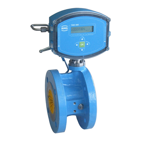
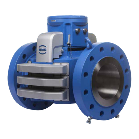
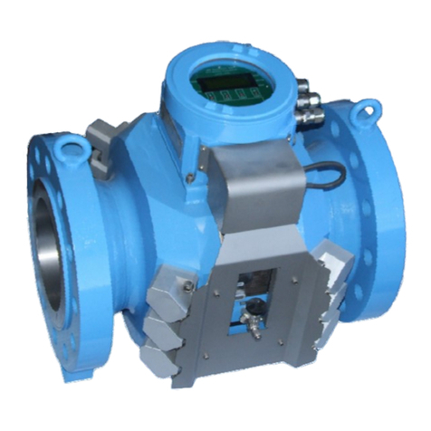
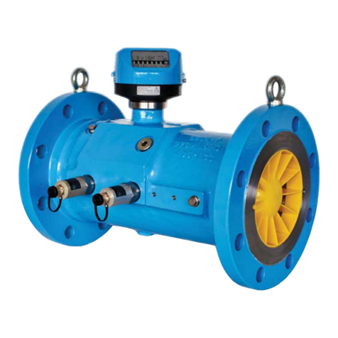
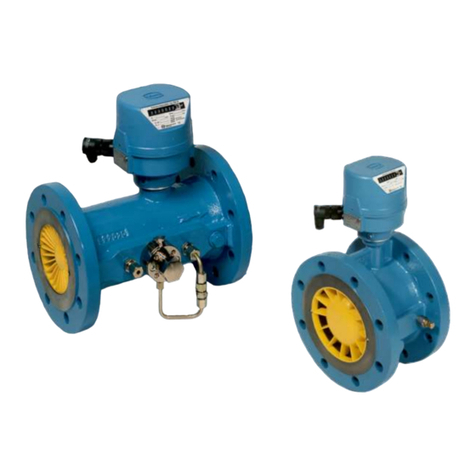
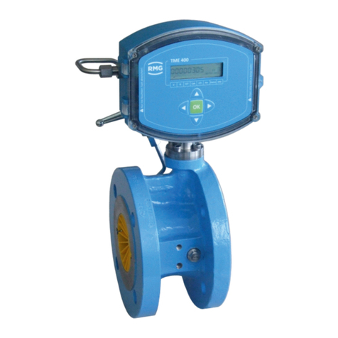
RMG TME400-VM User manual

Operating Manual
Turbine Meter TME 400-VM (..-VMF)
Status: January 22nd, 2024
Version: 11
Firmware: 1.12 / 11.12

Contact
Manual TME400-VMF · EN11 · January 22nd, 2024
Manufacturer
Contact our customer service department for tech-
nical information.
Address
RMG Messtechnik GmbH
Otto-Hahn-Straße 5
D-35510 Butzbach (Germany)
Main office
+49 6033 897 – 0
Service-Hotline
+49 6033 897 – 897
Fax
+49 6033 897 – 130
Email
You can register your product on our website at
https://www.rmg.com/en/help/device-registration. By
this you are helping us to improve our support
Translation of the
original document
The manual TME400VMF_manual_en_11 of
January 22nd, 2024 for the TME 400-VM and
TME 400-VMF turbine meters is a translation of the
the original German document
TME400VMF_manual_de_11.
Note
The latest version of this manual (and other devices)
can be downloaded at your convenience from our
Internet page:
www.rmg.com.
Created
June 2018
8th Revision
April 2022
8th Revision
November 2023
10th Revision
January 22nd, 2024
Document version and
language
Document version
TME400VMF_manual_en_11
January 22nd, 2024
Language
EN

Contents
Manual TME400-VMF · EN11 · January 22nd, 2024
I
TABLE OF CONTENTS
1INTRODUCTION................................................................................................................................... 1
1.1 STRUCTURE OF THE MANUAL................................................................................................................ 1
1.2 PURPOSE OF THE MANUAL................................................................................................................... 2
1.2.1 Abbreviations ....................................................................................................................... 2
1.2.2 Symbols................................................................................................................................ 3
1.2.3 Structure of notices............................................................................................................... 3
1.2.4 Working with the device ....................................................................................................... 4
1.2.5 Risk assessment and minimization ........................................................................................ 9
1.2.6 Applicability of the manual ................................................................................................. 12
1.2.7 Transport............................................................................................................................ 13
1.2.8 Scope of delivery................................................................................................................. 14
1.2.9 Storage............................................................................................................................... 15
1.2.10 Disposal.............................................................................................................................. 15
1.3 OVERVIEW OF VERSIONS ................................................................................................................... 16
1.3.1 Description ......................................................................................................................... 16
1.3.2 Device features ................................................................................................................... 16
1.3.3 Firmware............................................................................................................................ 17
1.3.4 Power supply ...................................................................................................................... 17
1.3.5 Area of application ............................................................................................................. 18
1.3.6 Use of gas meters for different gases .................................................................................. 19
1.4 AREAS OF APPLICATION .................................................................................................................... 20
1.4.1 Working principle of the TME 400 ....................................................................................... 21
1.4.2 Integrating the turbine meter into the pipeline.................................................................... 22
2INSTALLATION................................................................................................................................... 37
2.1 ELECTRICAL CONNECTIONS................................................................................................................. 37
3TME 400 ................................................................................... FEHLER! TEXTMARKE NICHT DEFINIERT.
3.1 DISPLAY FIELD ................................................................................................................................ 48
3.1.1 Display test......................................................................................................................... 49
3.1.2 Reset .................................................................................................................................. 49
3.1.3 Booting up.......................................................................................................................... 50
3.1.4 Battery replacement ........................................................................................................... 52
4OPERATION ....................................................................................................................................... 55
4.1 OPERATION CONCEPT....................................................................................................................... 55
4.1.1 Coordinate system.............................................................................................................. 55
4.1.2 Display and coordinate system............................................................................................ 57
4.1.3 Parameter protection.......................................................................................................... 57
4.2 PROGRAMMING ............................................................................................................................. 58
4.2.1 Programming with the programming buttons ..................................................................... 58
4.3 EQUATIONS IN THE TME 400............................................................................................................ 61
4.3.1 Variable description............................................................................................................ 61
4.3.2 Standard formula................................................................................................................ 61

CONTENTS
Manual TME400-VMF · EN11 · January 22nd, 2024
II
4.3.3 Coordinates in context ........................................................................................................ 61
4.4 SPECIAL SETTINGS ........................................................................................................................... 73
4.4.1 Configuration of the current output..................................................................................... 73
4.5 RMGVIEWTME ............................................................................................................................... 74
5TECHNICAL DATA............................................................................................................................... 75
5.1.1 Device types........................................................................................................................ 75
5.1.2 Inputs................................................................................................................................. 75
5.1.3 Outputs .............................................................................................................................. 76
5.1.4 Data interface..................................................................................................................... 76
5.1.5 Current loop connection...................................................................................................... 77
5.1.6 Cable .................................................................................................................................. 78
5.1.7 Cable connection ................................................................................................................ 78
5.1.8 Ground ............................................................................................................................... 80
5.2 OVERVIEW OF MATERIALS IN USE ........................................................................................................ 82
6ERROR MESSAGES ............................................................................................................................. 83
APPENDIX.............................................................................................................................................. 85
AMODBUS......................................................................................................................................... 85
BSTRUCTURE OF THE ARCHIVES............................................................................................... 93
B1 ARCHIVE SIZE............................................................................................................................. 93
B2 ARCHIVE TYPES ......................................................................................................................... 93
B2.1 PARAMETER ARCHIVES........................................................................................................... 94
B2.2 EVENT ARCHIVES.................................................................................................................... 94
B2.3 MEASURED VALUES ARCHIVES................................................................................................ 95
B3 CALCULATION OF THE STORAGE SIZE ......................................................................................... 96
B4 ARCHIVE HEADER....................................................................................................................... 96
B5 READING THE ARCHIVE DATA VIA MODBUS ................................................................................. 99
CDIMENSIONS................................................................................................................................ 101
DMEASURING RANGES FOR TME 400-VMF/ TME 400-VCF .................................................. 106
EMEASURING ACCURACY FOR TME 400-VM.......................................................................... 107
FTYPE PLATE ................................................................................................................................ 109
GSEAL DIAGRAMS ........................................................................................................................ 112
HLATER INSTALLATION OF THE POWER MODULE............................................................... 113
ISPARE PARTS AND ACCESSORIES....................................................................................... 115
JCERTIFICATES AND APPROVALS .......................................................................................... 128

1 Introduction
Manual TME400-VMF · EN11 · January 22nd, 2024
1
1 Introduction
1.1 Structure of the manual
The introduction of this manual comprises two parts. The first part lists general speci-
fications; the symbols used in the manual and the structure of notices are presented
and a risk assessment is provided. The differences between the TME 400-VM and
TME 400-VMF turbine meters are explained. If there is no explicit reference to differ-
ences, the TME 400 is superordinate for both versions of the turbine meter.
Note
This manual refers to the TME 400-VM and TME 400-VMF instead of the com-
plete turbine meter.
In addition, the first part includes specifications for the transport and storage of the
TME 400. The second part of the introduction describes the features and areas of ap-
plication of the TME 400; basic standards are listed and the pressure and tempera-
ture ranges in which the TME 400 can and may be used are pre-adjusted.
The second chapter describes the electrical and mechanical commissioning of the
TME 400. An explanation of how to achieve the reliable commissioning of the meter
and high precision is provided.
The third chapter explains the displays of the TME 400. It explains resetting, booting
and replacement of the battery.
The settings of the TME 400 are explained in chapter four. In particular, all adjustable
parameters are provided there with some explanations.
The fifth chapter summarizes the technical data and the sixth chapter provides a list
of error messages.
The appendix provides details about the Modbus, measurements, type plate and seal
plans. Then the certificates and approvals are listed.

1 Introduction
Manual TME400-VMF · EN11 · January 22nd, 2024
2
1.2 Purpose of the manual
This manual provides information that is necessary for fault-free and safe operation.
The TME 400 was designed and produced according to the state of the art and gen-
erally recognized safety standards and directives. However, its use can entail dan-
gers that are avoidable by complying with this manual. The device must only be used
as intended and in technically sound condition.
Warning
Unintended use voids all warranty claims and the TME 400 can also lose its
approvals.
1.2.1 Abbreviations
The following abbreviations are used:
TME 400-VM
The TME 400-VM is a turbine meter which is used for non-cus-
tody-transfer volume measurement (Volume Measurement) of the
operating volume of non-aggressive gases and combustion fuels
is used.
TME 400-VMF
The TME 400-VMF is a turbine gas meter that is used in custody-
transfer applications (Fiscally). The designation TME 400-VMF
comprises all turbine meters.
TME 400-VC
The TME 400-VC also enables calculation of the standard volume
flow (Volume Corrector) from the operating volume flow in non-
custody-transfer applications.
TME 400-VCF
The TME 400-VCF is used in custody-transfer applications (Fis-
cally). In addition to the turbine meter, the TME 400-VCF designa-
tion also includes the volume corrector.
Note
This manual only describes the TME 400-VM and TME 400-VMF.

1 Introduction
Manual TME400-VMF · EN11 · January 22nd, 2024
3
MessEG
Measurement and Calibration Act
Law on the marketing and provision of measuring devices in the
market, their use and calibration, valid since 1/1/2015
MessEV
Measurement and Calibration Regulation
Regulation on the marketing and provision of measuring devices in
the market and on their use and calibration; 12/11/2014
MID
Measurement Instruments Directive
PTB
Physikalisch-Technische Bundesanstalt
[German National Test Authority]
Vo
original meter reading (Volume) of a mechanical counter
approx.
approximately
max.
maximum
min.
minimum
1.2.2 Symbols
The following symbols are used:
1, 2, …
Identifies steps for work tasks
..
1.2.3 Structure of notices
The following notices are used:
Danger
This warning notice informs you of imminently threatening dangers that can
arise due to misuse/operator error. If these situations are not avoided, death
or severe injuries can occur.

1 Introduction
Manual TME400-VMF · EN11 · January 22nd, 2024
4
Warning
This warning notice informs you of potentially dangerous situations that can
arise due to misuse/operator error. If these situations are not avoided, minor
injuries can occur.
Caution
This notice informs you of potentially dangerous situations that can arise
due to misuse/operator error. If these situations are not avoided, damage to
the device or nearby property can occur.
Note
This notice informs you of potentially dangerous situations that can arise
due to misuse/operator error. If these situations are not avoided, damage to
the device or nearby property can occur.
This notice can provide you with helpful tips to make your work easier. This
notice also provides you with further information about the device or the
work process in order to prevent operator error.
1.2.4 Working with the device
1.2.4.1 Safety notices Danger, Warning, Caution and Note
Danger
All of the following safety notices must be observed!
Disregard of the safety notices can result in danger to the life and limb or environ-
mental and property damage.
Bear in mind that the safety warnings in this manual and on the device cannot cover
all potentially dangerous situations, because the interaction of various conditions can
be impossible to foresee. Merely following the instructions may not suffice for correct
operation. Always remain attentive and consider potential consequences.

1 Introduction
Manual TME400-VMF · EN11 · January 22nd, 2024
5
•Read this operating manual and especially the following safety notices care-
fully before working with the device for the first time.
•Warnings are provided in the operating manual for unavoidable residual risks
for users, third parties, equipment or other property. The safety instructions
used in this manual do not refer to unavoidable residual risks.
•Only operate the device in fault-free condition and in observance of the operat-
ing manual.
•Compliance with local statutory accident prevention, installation and assembly
regulations is also mandatory.
Caution
All notices in the manual must be observed. Use of the TME 400 is only per-
mitted in accordance with the specifications in the operating manual. RMG
assumes no liability for damages arising due to disregard of the operating
manual.
Danger
Service and maintenance tasks or repairs that are not described in the oper-
ating manual must not be carried out without prior consultation with the man-
ufacturer. The device must not be opened forcefully.
Caution
The TME 400 is approved for custody-transfer applications. For this purpose,
it is sealed before deliver and settings specified by the approval authority are
locked. These seals, software or hardware locks must not be damaged, de-
stroyed or removed!
In this case, the TME 400 loses its official certification!
The TME 400 can only be approved for officially certified operation after a re-
newed inspection by an officially recognized inspection authority or calibra-
tion officials and an additional inspection of additional settings. The calibra-
tion official must re-apply the seals after the inspection.

1 Introduction
Manual TME400-VMF · EN11 · January 22nd, 2024
6
Observe the following, in particular:
•Changes to the TME 400 are not permitted.
•The technical specifications must be observed and followed for safe operation.
Performance limits must not be exceeded (chapter 5 Technical data)
•For safe operation, the TME 400 must only be used in the scope of the in-
tended use (chapter 1.3 Overview of versions).
•The TME 400 complies with current standards and regulations. However, dan-
ger can arise with misuse.
1.2.4.2 Dangers during commissioning
Initial commissioning
The initial commissioning must only be carried out by
specially trained personnel (training by RMG) or RMG
service personnel.
Note
An acceptance test certificate must be created during the commissioning.
This, the operating manual and the EU Declaration of Conformity must be
stored so that they are always readily available.
All sharp edges on the device were removed, insofar as possible. However,
personal protective equipment provided by the operator must be worn during
all work.
Danger
Install the device as specified in the operating manual. If the device is not in-
stalled as specified in the operating manual, there may be a risk that ade-
quate explosion protection is not provided.
The explosion protection is lost!

1 Introduction
Manual TME400-VMF · EN11 · January 22nd, 2024
7
Danger
Inadequately qualified persons working on the equipment are unable to cor-
rectly estimate dangers. Explosions can be triggered. Only work on the
equipment if you have the appropriate qualifications.
Components can be damaged if you do not use suitable tools and materials.
Use tools that are recommended for the respective work in the operating
manual.
Mechanical installation
Mechanical installation must only be performed by appro-
priately qualified technicians.
Electrical installation
Installation on electrical components must only be carried
out by qualified electricians.
Mechanical and/or
electrical installation
These qualified personnel require training specifically for
work in hazardous areas. Qualified personnel are persons
who have training / education in accordance with DIN
VDE 0105, IEC 364 or comparable standards.
Danger
Installation and removal of the TME 400 must only take place in an explosion-
free, pressure-free atmosphere. The descriptions in the operating manual
must be observed. In general, it is recommended that the replacement should
only be carried out by RMG Service.
A leak test must be carried out after work on pressurized components.
All of the above points also apply to repair and maintenance tasks and in
general when opening the meter is necessary.
Flange fastening elements, fastening screws, screw couplings and check
valves, the oil supply, pressure relief connections, valves, HF pulse genera-
tors, protective pipes and swivel adapters must not be loosened during oper-
ation.

1 Introduction
Manual TME400-VMF · EN11 · January 22nd, 2024
8
1.2.4.3 Dangers during maintenance and repair
Operating personnel
The operating personnel use and operate the device in
the scope of the intended use.
Maintenance personnel
Work on the device must only be carried out by qualified
personnel who can carry out the respective tasks on the
basis of their technical training, experience and familiarity
with the applicable standards and requirements. These
qualified personnel are familiar with the applicable statu-
tory regulations for accident prevention and can inde-
pendently recognize and avoid potential dangers.
Maintenance and clean-
ing
Maintenance and cleaning must only be performed by ap-
propriately qualified technicians.
Danger
Inadequately qualified persons working on the equipment are unable to cor-
rectly estimate dangers. Explosions can be triggered. If work on live equip-
ment must be conducted in hazardous areas, sparks that are created can trig-
ger an explosion.
Danger
The device can be damaged if it is not cleaned as specified in the operating
manual. Only clean the device as specified in the operating manual.
Components can be damaged if you do not use suitable tools. The explosion
protection is lost.
- Only clean the device with a damp cloth!
Danger
The TME 400 must only be used as intended! (Chapter 1.3
Overview of versions). Prevent use of the TME 400 as a potential climbing aid
or use of attachments of the TME 400 as potential handles!

1 Introduction
Manual TME400-VMF · EN11 · January 22nd, 2024
9
1.2.4.4 Qualification of personnel
Note
In general, the following is recommended for all persons working with or on
the TME 400:
•Training / education for work in hazardous areas.
•The capacity to be able to correctly estimate dangers and risks when
working with the TME 400 and all connected devices. Possible dangers
include components that are under pressure and consequences of in-
correct installation.
•Recognition of dangers that can arise from the flow medium that is
used.
•Training / education by RMG for work with gas measuring devices.
•Education / instruction in all national standards and directives to be
complied with for the work to be carried out on the device.
1.2.5 Risk assessment and minimization
According to assessment by qualified employees of RMG, the TME 400 is subject to
risks during its use. Risks can arise, for example, due to high pressures and occa-
sionally due to pressures that are too low. Work outside of the permissible tempera-
ture range can also lead to dangers. Impermissible current and voltage values can
trigger explosions in hazardous areas. The risk assessment requires an emptying
and ventilation of the pipeline for connection with installation and removal of a tur-
bine. Then and only then is it assured that there is not an hazardous gas mixture in
the pipeline. Naturally, work must only be carried out by trained personnel (see chap-
ter 1.2.4.4 Qualification of personnel), who are also trained to recognize suitable tools
and use them exclusively. The risks were summarized alongside development and
measures were taken to minimize these risks.
Measures for risk minimization:
- All pressurized parts are designed in accordance with AD 2000 rules and regula-
tions, Pressure Equipment Directive, Annex 1
- The complete pressure design has been inspected by TÜV Hessen
- All pressurized parts have been manufactured with a material certificate; there is
an uninterrupted change of batch tracing of pressurized components
- The mechanical properties of all relevant pressurized components have been
subjected to tension tests, notch impact bending tests and hardness tests

1 Introduction
Manual TME400-VMF · EN11 · January 22nd, 2024
10
- Non-destructive testing was also carried out: X-ray and ultrasonic inspection of
the meter housing for defective points in material, surface crack testing with mag-
netic powder and a color penetration process
- Strength tests for components were conducted at 1.5 times the nominal pressure
for the pressure testing; the leak testing for the assembly was conducted at 1.1.
times the nominal pressure. Certificates were issued for successfully passed tests
- The maximum operating pressure and the permissible temperature range are
specified on the type plate of the device. Operation of the device is only permitted
within these specified ranges.
- A maximal temperature difference of ΔT ≤ 100°K between the inside and outside
of the TME 400 must be respected.
- Additional external forces and torques were not taken into account in the pressure
dimensioning.
- In the event that the pressure equipment is to be marketed and put into operation
as an assembly within the meaning of the Pressure Equipment-Directive, an ex-
amination of the assembly must be provided at the latest during the final and
pressure tests.
Otherwise, the commissioning inspector must explicitly point out that a test of the
equipment location with safety function still has to be performed at the installation
site.

1 Introduction
Manual TME400-VMF · EN11 · January 22nd, 2024
11
Danger
The following applies for work in hazardous areas (all zones):
- The pulse generators of the turbine meter must be connected to intrin-
sically safe power circuit only.
- Only tools that are approved for Ex Zone 1 are permitted for mainte-
nance and repair tasks.
- Otherwise, work must only be carried out when there is not an explo-
sive atmosphere.
- The risk of ignition due to impact or friction must be avoided.
- Work on devices which are used in hazardous areas must be carried
out by qualified electrical engineers with special capabilities for work
in hazardous areas.
- The wiring / installation in hazardous areas must only be carried out by
trained personnel in accordance with EN60079-14 and in observance of
national regulations.
- Qualified persons must satisfy the definitions in accordance with DIN
EN 0105 or IEC 364 or directly comparable standards.
- If one or more power circuits are used, it must be ensured that the per-
missible limit values according to the EC type approval certificate are
not exceeded when choosing the cables.
- Every Ex signal circuit must be routed with a dedicated cable which
must be guided through the appropriate PG screw coupling.
- Permanent installation of the intrinsically safe cable is mandatory.
Danger
In addition, the following applies for work in hazardous areas (all zones):
- Only trained and instructed personnel are permitted. Work on the
measuring system must only be carried out from qualified persons and
inspected by responsible qualified supervisors.
- Qualified persons have been authorized by the person responsible for
safety of personnel to carrying out such work on the basis of their
training, experience or instruction and familiarity with applicable
standards, provisions, accident prevention regulations and system
conditions. It is essential that these persons are able to recognize and
avoid potential dangers in good time.

1 Introduction
Manual TME400-VMF · EN11 · January 22nd, 2024
12
1.2.6 Applicability of the manual
This manual describes the TME 400. TME 400 is generally only part of a complete
system. The manuals of the other components of the system must be observed. If
you find contradictory instructions, contact RMG and/or the manufacturers of the
other components.
Note
Ensure that the power data of the current connection matches the specifica-
tions on the type plate. Ensure that the limit values specified in the conform-
ity certificate (see appendix) for the devices to be connected are not ex-
ceeded.
Observe any applicable national regulations in the country of use. Use cable
that is appropriate for the cable fittings.
Danger
Only work on the equipment if you have the appropriate training and qualifi-
cations.
Attention: Risk of destruction due to body electricity, e.g. due to the rubbing
of clothing.
1.2.6.1 Danger during operation
Observe the specifications of the system manufacturer and/or system operator.
1.2.6.2 Dangers of operation in EX areas
Only operate the device in fault-free and complete condition.
If you make technical changes to the device, safe operation can no longer be guaran-
teed.
Danger
Only use the device in its original condition. The TME 400 is permitted for op-
eration in Ex Protection Zone 1, but only within the permissible temperature
range (chapter 1.3.5.2 Temperature ranges).

1 Introduction
Manual TME400-VMF · EN11 · January 22nd, 2024
13
1.2.6.3 Responsibility of the operator
As the operator, you must ensure that only adequately qualified personnel work on
the device. Ensure that all employees who work with the device have read and un-
derstood this manual. You are also obligated to train personnel regularly and inform
them of the dangers. Ensure that all work on the device is carried out exclusively by
qualified persons and inspected by responsible qualified supervisors. The responsi-
bilities for installation, operation, fault rectification, maintenance and cleaning must be
clearly regulated. Instruct your personnel with regard to the risks involved with work-
ing with the device.
1.2.7 Transport
The device is packaged specific to the transport requirements for each customer. En-
sure safe packaging that absorbs light impact and vibrations is used for any further
transport. Nevertheless, inform the transport company that all types of impact and vi-
brations should be avoided during transport.

1 Introduction
Manual TME400-VMF · EN11 · January 22nd, 2024
14
Warning
Risk of injury during transport
Any foot screws must be mounted if they are provided as a transport safe-
guard to prevent rolling and tipping. Additional measures must be taken to
ensure that impermissible rolling and tipping are prevented.
Only use the provided lifting eyes / ring screws to lift the meter. Please ob-
serve the relevant permissible loads for the lifting equipment. Prior to lifting,
ensure that the load is securely fastened. Do not stand under suspended
loads.
The device can slip, topple over or fall down when being lifted and set down.
The device can fall over if the bearing capacity of the lifting equipment is dis-
regarded. There is a risk of severe injury for nearby persons.
If the device is delivered on a Euro pallet, the device can be transported on
the pallet using a pallet truck or forklift.
The gas meters and accessories must be protected from jarring and vibra-
tions during transport.
The gas meters or any inlet/outlet pieces have a flange as an end piece. The
flanges are sealed with a protective sticker or fitted with a plastic dummy
plug. The protective stickers and/or dummy plugs must be removed without
leaving any residue prior to installation in the pipeline. Residue from this film
changes the flow and causes measuring errors!
This protection must be re-applied to the flanges for transport or storage of
the device.
1.2.8 Scope of delivery
The scope of delivery can differ depending on the optional orders. The following is
"normally” included in the scope of delivery:
Part
Quan-
tity
TME 400-VM (or TME 400-VMF) turbine meter
1
1 Lubricating oil bottle
Op-
tional
Lubricating instructions
1
Manual
1

1 Introduction
Manual TME400-VMF · EN11 · January 22nd, 2024
15
Test log
1
Calibration certificate
1
Material test certificate
1
Strength test certificate 3.1.
Op-
tional
1.2.9 Storage
Avoid extended periods of storage. After storage, inspect the device for damage and
test for correct function. Contact the RMG service department to arrange for inspec-
tion of the device after a storage period of longer than one year. For this purpose, re-
turn the device to RMG.
Note
Storage must take place in a dry and protected room.
It must be ensured that all open pipes are sealed.
1.2.10 Disposal
Dispose of the packaging and protective material (e.g. drying mats) as well as the
parts and devices supplied in an environmentally friendly manner in accordance
with the country-specific laws, standards and guidelines.
When disposing of the device, observe the overview of the materials used on page
82.
Before disposing of the device, remove the batteries, mask their contacts and dis-
pose of the batteries separately.
Residual amounts of lubricating oil in the bottles supplied must also be disposed of
separately.
Make sure that your disposal company is authorized to dispose of the relevant parts
and materials.

1 Introduction
Manual TME400-VMF · EN11 · January 22nd, 2024
16
1.3 Overview of versions
1.3.1 Description
The TME 400-VM is a turbine meter which is used for volume measurement of the
operating volume of non-aggressive gases and burnable gas. The operating volume
flow is determined based on the turbine speed, which is scanned by means of a Wie-
gand or Reed sensor element and then added together in internal archives. The re-
sult is registered in an electronic meter.
There are a high-frequency (HF) and a low-frequency (LF) output, where the HF out-
put is preferably used as a flow sensor for control tasks and remote transmission. In
addition to these outputs, the TME 400 VM has a serial RS 485 interface for digital
data readings and parameterization. The TME 400-VM is used in non-custody-
transfer applications.
The TME 400-VMF (MID) is the turbine meter for custody-transfer applications and
has an equivalent function and operating method to the TME 400-VM. The essential
difference is the 2-channel measuring head version. It is used in custody-transfer
applications.
1.3.2 Device features
TME 400-VM
•Non-custody-transfer measurements
•Electronic meter
•Alarm output
•Optionally available in a version with remote meter
(distance from meter head to meter: 10 m;
see appendix C Dimensions)
•2x pulse inputs selectable for Reed, Wiegand and external pulse transmitters
(remote meters)
•1x contact input
•1x HF output
(input pulse of pulse input 1 is output with defined pulse width of 1 ms)
•1x LF output with defined pulse width (20 ms, 125 ms or 250 ms)
•1x RS485 with external power supply
•1x optional power module
•Power supply via 3.6V lithium cell or an external power supply which is assigned
to the RS485 interface (supply via power module alone is not adequate and a
battery is required for support)
•Archive memory for events, parameters, measurements
Other manuals for TME400-VM
1
This manual suits for next models
3
Table of contents
Other RMG Measuring Instrument manuals
Popular Measuring Instrument manuals by other brands
GW Instek
GW Instek GSP-9300 user manual
REED
REED R6010 instruction manual

Wavelength References
Wavelength References ClarityPlus Operator's manual
Vernier
Vernier Go Direct ORP manual
GREISINGER
GREISINGER GMH 5630 operating manual

Katronic Technologies
Katronic Technologies KATflow 200 operating instructions

