manuals.online logo
Brands
  1. Home
  2. •
  3. Brands
  4. •
  5. Gessi
  6. •
  7. Plumbing Product
  8. •
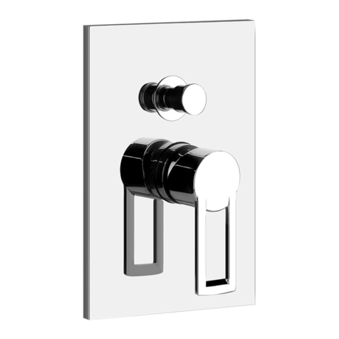
  9. Gessi OXYGENE 35045 User manual

Gessi OXYGENE 35045 User manual

Gessi SpA - Parco Gessi
13037 Serravalle Sesia (Vercelli) - Italy
Phone +39 0163 454111 - Facsimile +39 0163 459273
www.gessi.com - [email protected]
MANUALE DI INSTALLAZIONE
INSTALLATION MANUAL
MANUEL D’INSTALLATION
INSTALLATIONSANWEISUNG
MANUAL DE INSTALACIÓN
РУКОВОДСТВО ПО УСТАНОВКЕ
OXYGENE
Art. 35045
2
Indice - Index - Index - Inhaltsverzeichnis - Indice - Содержание
Contenuto della confezione.....................................................................................................................
Caratteristiche tecniche...........................................................................................................................
Preliminari di installazione.......................................................................................................................
Installazione..............................................................................................................................................
Installazione corpo incasso........................................................................................................
Collaudo dell’impianto.................................................................................................................
Rimozione della protezione in plastica......................................................................................
Rilevamento della profondità di incasso....................................................................................
Installazione del Kit prolunga......................................................................................................
Installazione delle parti esterne..................................................................................................
Regolazione del blocco di sicurezza della temperatura...........................................................
Funzionamento..........................................................................................................................................
Package content.......................................................................................................................................
Technical features.....................................................................................................................................
Installation preliminaries...........................................................................................................................
Installation.................................................................................................................................................
Installation of built-in body..........................................................................................................
System test...................................................................................................................................
Removal of the plastic protection...............................................................................................
Detecting the built-in depth.........................................................................................................
Extension kit installation.............................................................................................................
External parts installation...........................................................................................................
Adjustment of the safety temperature lock ...............................................................................
Operation...................................................................................................................................................
Contenu de l’emballage............................................................................................................................
Caractéristiques techniques....................................................................................................................
Préliminaires d’installation.......................................................................................................................
Installation.................................................................................................................................................
Installation corps encastrement.................................................................................................
Test du système...........................................................................................................................
Elimination de la protection en plastique...................................................................................
Détection de la profondeur d’encastrement...............................................................................
Installation du Jeu rallonge.........................................................................................................
Installation des parties extérieures............................................................................................
Réglage du bloc de sécurité de la température.........................................................................
Fonctionnement........................................................................................................................................
Inhalt der Verpackung...............................................................................................................................
Technische Eigenschaften.......................................................................................................................
Vorbereitungseingriffe für die Installation...............................................................................................
Installation.................................................................................................................................................
Installation des Einbaukörpers...................................................................................................
Abnahme der Anlage...................................................................................................................
Entfernen der Schutzhülle aus Kunststoff.................................................................................
Ermitteln der Einbautiefe.............................................................................................................
Installation vom Verlängerungssatz...........................................................................................
Installation der externen Bestandteile........................................................................................
Einstellen der Sicherheitsblockierung für die Temperatur........................................................
Funktion.....................................................................................................................................................
4/5
5/8
9/10
11/40
11/22
14/19
23
24/25
26/29
30/35
36/39
41/47
4/5
5/8
9/10
11/40
11/22
14/19
23
24/25
26/29
30/35
36/39
41/47
4/5
5/8
9/10
11/40
11/22
14/19
23
24/25
26/29
30/35
36/39
41/47
4/5
5/8
9/10
11/40
11/22
14/19
23
24/25
26/29
30/35
36/39
41/47
3
Indice - Index - Index - Inhaltsverzeichnis - Indice - Содержание
Contenido de la caja.................................................................................................................................
Características técnicas...........................................................................................................................
Preliminares de instalación......................................................................................................................
Instalación.................................................................................................................................................
Instalación cuerpo por empotrar................................................................................................
Ensayo de la instalación.............................................................................................................
Remoción de la protección de plástico......................................................................................
Detección de la profundidad de empotre...................................................................................
Instalación del juego alargadera................................................................................................
Instalación de las paredes externas..........................................................................................
Regulación del bloque de seguridad de la temperatura...........................................................
Funcionamiento.........................................................................................................................................
Содержимое упаковки...........................................................................................................................
Технические характеристики................................................................................................................
Предварительная подготовка к установке........................................................................................
Установка.................................................................................................................................................
Установка встроенного корпуса.............................................................................................
Испытание системы..................................................................................................................
Удаление пластиковой защиты..............................................................................................
Определение глубины встраивания......................................................................................
Установка комплекта удлинителя..........................................................................................
Установка наружных частей....................................................................................................
Регулировка предохранительной блокировки температуры............................................
Использование........................................................................................................................................
4/5
5/8
9/10
11/40
11/22
14/19
23
24/25
26/29
30/35
36/39
41/47
4/5
5/8
9/10
11/40
11/22
14/19
23
24/25
26/29
30/35
36/39
41/47
4
A
B
C
D
E
F
GH
L
M
Contenuto della confezione - Package content - Contenu de l’emballage -
Inhalt der Verpackung - Contenido de la caja - Содержимое упаковки
5
Pressione - Pressure
[bar]
Uscita - Outlet [l/min]
1° 2° 3°
0.5 16 15,5 15
122,5 22 21,5
232 31,5 31
339 38,5 38
445 44,5 44
550 49,5 49
Contenuto della confezione:
A - Corpo incasso
B - Piastra di copertura
C - Guarnizione a parete
D - Fermo di regolazione della temperatura
E - Chiave esagonale
F - Kit prolunga
G - Maniglia per regolazione temperatura
H - Maniglie di comando
L - Manuali di installazione e manutenzione
M - Guarnizione per piastra di copertura
Package content:
A - Built-in body
B - Cover plate
C - Wall gasket
D - Temperature adjustment stop
E - Hexagonal wrench
F - Extension kit
G - Handle for temperature adjustment
H - Control handles
L - Installation and maintenance manuals
M - Gaskets for covering plate
Contenu de l’emballage:
A - Corps encastrement
B - Plaque de couverture
C - Gaine murale
D - Arrêts de réglage de la température
E - Clé hexagonale
F - Jeu rallonge
G - Poignée réglage température
H - Poignée de commandee
L - Manuels d’installation et entretien
M - Gaine pour plaque de couverture
Inhalt der Verpackung:
A - Einbaukörper
B - Abdeckplatte
C - Wanddichtung
D - Feststellvorrichtung für die Temperatureinstellung
E - Inbusschlüssel
F - Verlängerungssatz
G - Griff zur Temperatureinstellung
H - Steuergriffe
L - Installations- und Wartungsanweisungen
M - Dichtung für die Abdeckplatte
Contenido de la caja:
A - Cuerpo por empotrar
B - Placa de cobertura
C - Junta de pared
D - Retén de regulación de la temperatura
E - Llave hexagonal
F - Juego alargadera
G - Maneta para la regulación de la temperatura
H - Manetas de mando
L - Manuales de instalación y mantenimiento
M - Junta para la placa de cobertura
Содержимое упаковки:
A - Встроенный корпус
B - Закрывающая пластина
C - Настенное уплотнение
D - Регулировочный стопор температуры
E - Шестигранный ключ
F - Комплект удлинителя
G - Регулировочная ручка температуры
H - Ручки управления
L - Руководства по установке и обслуживанию
M - Уплотнение закрывающей пластины
Contenuto della confezione - Package content - Contenu de l’emballage -
Inhalt der Verpackung - Contenido de la caja - Содержимое упаковки
Caratteristiche tecniche - Technical features - Caractéristiques techniques -
Technische Eigenschaften - Características técnicas - Технические характеристики
6
Calda / Hot Fredda / Cold
Uscita / Outlet
Dati tecnici:
- Pressione minima d’esercizio 0,5 bar
- Pressione massima d’esercizio 5 bar
- Pressione d’esercizio consigliata 3 bar (in caso di pressione dell’acqua superiore ai 5 bar si consiglia
l’installazione di riduttori di pressione)
- Blocco di sicurezza a 38 °C
- Temperatura minima di esercizio 3 °C - consigliata 15 °C - FREDDA
- Temperatura massima di esercizio 80 °C - consigliata 65 °C - CALDA
- Differenziale termico consigliato 50 °C
- Sistema di sicurezza con blocco dell’ erogazione in caso di mancanza di una delle due acque
Funzionamento:
- Sia con scaldabagni a gas che elettrici ad accumulo
- Impianti centralizzati
- Caldaie murali
- Filtri in acciaio inox per il trattamento delle impurità
Attenzione: consultare il proprio idraulico di fiducia per la scelta del dispositivo di riscaldamento dell’acqua
più idoneo.
Technical data:
- Minimum working pressure 0,5 bar
- Maximum working pressure 5 bar
- Recommended working pressure 3 bar (in case of water pressure higher than 5 bar it is recommended to
install pressure reducers)
- Safety lock at 38 °C
Altezza da terra
consigliata.
Recommended
height from
ground.
Uscita / Outlet
Uscita / Outlet
Caratteristiche tecniche - Technical features - Caractéristiques techniques -
Technische Eigenschaften - Características técnicas - Технические характеристики
VISTA DA DIETRO
REAR VIEW
VUE POSTERIEURE
RÜCKANSICHT
VISTA POR DETRÁS
ВИД СЗАДИ
Dimensioni in mm - Measures in mm - Dimensions en mm - Maß im mm - Medidas en milímetros - Размеры выражены в мм
7
- Minimum working temperature 3 °C - recommended 15 °C - COLD
- Maximum working temperature 80 °C - recommended 65 °C - HOT
- Recommended thermal differential 50 °C
- Safety system with flow stop in case of lack of one of the two waters
Operation:
- Either with gas or electric accumulation boilers
- Centralised systems
- Wall boilers
- Filters in stainless steel for the treatment of impurities
Warning: contact the plumber for the choice of the best water heating device.
Données techniques:
- Pression minimum d’exercice 0,5 bar
- Pression maximum d’exercice 5 bar
- Pression d’exercice conseillée 3 bar (en cas de pression de l’eau supérieure aux 5 bar nous conseillons
l’installation de réducteurs de pression)
- Bloc de sécurité à 38 °C
- Température minimum d’exercice 3 °C - conseillée 15 °C - FROIDE
- Température maximum d’exercice 80 °C - conseillée 65 °C - CHAUDE
- Différentiel thermique conseillé 50 °C
- Système de sécurité avec le bloc de la distribution en cas de manque d’une des deux eaux
Fonctionnement:
- Soit avec des chauffe-eaux à gaz, électriques à accumulation
- Installations centrales
- Chaudières au mur
- Filtres en acier inox pour le traitement des impuretés
Attention: consulter le plombier pour le choix du dispositif de réchauffement de l’eau le plus approprié.
Technische Daten:
- Minimaler Betriebsdruck 0,5 bar
- Maximaler Betriebsdruck 5 bar
- Empfohlener Betriebsdruck 3 bar (sollte der Wasserdruck einen Wert von 5 bar überschreiten, empfiehlt
es sich Druckminderventile zu installieren)
- Sicherheitsblockierung bei 38 °C
- Minimale Betriebstemperatur 3 °C - empfehlenswert 15 °C - KALT
- Maximale Betriebstemperatur 80 °C - empfehlenswert 65 °C - WARM
- Empfohlenes Thermodifferential 50 °C
- Sicherheitssystem zum Unterbrechen der Wasserabgabe, sollte eine der beiden Wasserzuleitungen
ausfallen
Funktionstätigkeit:
- Sowohl mit Gasbadeofen, als auch mit elektrischen Heißwasserspeichern
- Zentralisierte Anlagen
- Wandheizkessel
- Filter aus Inoxstahl für die Behandlung von Verunreinigungen
Achtung: Für eine Wahl der am besten geeigneten Wasserheizvorrichtung wenden Sie sich bitte an Ihren
Vertrauensinstallateur.
Datos técnicos:
- Presión mínima de ejercicio 0,5 bar
- Presión máxima de ejercicio 5 bar
- Presión de ejercicio aconsejada 3 bar (en caso de presión del agua superior a los 5 bar, les aconsejamos
instalar unos reductores de presión)
- Bloqueo de seguridad a 38 °C
Caratteristiche tecniche - Technical features - Caractéristiques techniques -
Technische Eigenschaften - Características técnicas - Технические характеристики
8
- Temperatura mínima de ejercicio 3 °C - recomendada 15 °C - FRÍA
- Temperatura máxima de ejercicio 80 °C - recomendada 65 °C - CALIENTE
- Diferencial térmico recomendado 50 °C
- Sistema de seguridad con bloqueo de seguridad en caso de falta de una de las dos aguas
Funcionamiento:
- Con calderas tanto de gas como eléctricas por acumulación
- Instalaciones centralizadas
- Calderas murales
- Filtros de acero inoxidable para el tratamiento de las impurezas
Cuidado: consúltense con Su fontanero para elegir el dispositivo de calefacción del agua más adecuado.
Технические данные:
- Минимальное рабочее давление 0,5 баров
- Максимальное рабочее давление 5 баров
- Рекомендованное рабочее давление 3 бара (в случае давление воды выше 5 баров, рекомендуется
установка редукторов давления)
- Предохранительное ограничение температуры на 38 °C
- Минимальная рабочая температура: 3 °C, рекомендуемая: 15 °C - для ХОЛОДНОЙ воды
- Максимальная рабочая температура: 80 °C, рекомендуемая 65 °C - для ГОРЯЧЕЙ воды
- Рекомендуемая разница температуры: 50 °C
- Предохранительная система с перекрытием подачи в случае отсутствия холодной или горячей
воды
Использование:
- Как с газовыми водонагревателями, так и с электроводонагревателями накопительного типа
- Централизованные системы
- Настенные котлы
- Фильтры из нержавеющей стали для улавливания примесей
Внимание: для выбора наиболее пригодного средства нагрева воды обращайтесь к вашему
сантехнику.
Caratteristiche tecniche - Technical features - Caractéristiques techniques -
Technische Eigenschaften - Características técnicas - Технические характеристики
9
Preliminari - Pre-installation information - Préliminaires -
Vorbereitung - Preliminares - Предварительная подготовка
Prima dell’installazione e messa in funzione
Attenzione! I tubi d’alimentazione devono essere sciacquati con cura prima dell’installazione del
miscelatore, in modo che non rimangano trucioli, residui di saldatura o canapa, o altre impurità all’interno
dei tubi. Attraverso tubazioni non sciacquate a fondo o attraverso la rete idrica generale, nel miscelatore
possono entrare corpi estranei in grado di danneggiare guarnizioni/o-ring e/o cartucce/vitoni.
Si raccomanda pertanto di dotare anche l’impianto generale di filtri.
Before installation and setting to work
Attention! The feeding pipes have to be rinsed carefully before the installation of the mixer so that there
won’t remain shavings, sealing or hemp residues, or other impurities inside the pipes. Through pipes not
thoroughly rinsed or through the general water network, in the mixer foreign bodies can enter that could
damage gaskets /o-ring and/or cartridges/headvalves.
So filters should be installed also on the general system.
Avant l’installation et la mise en fonction
Attention! Les tuyaux d’alimentation doivent être rincés avec soin avant l’installation du mélangeur, de
sorte que ils ne restent pas de copeaux, des restes de soudage ou de chanvre, ou d’autres impuretés à
l’intérieur des tuyaux. A travers les conduites non rincées à fond ou à travers le réseau hydrique général,
dans le mélangeur peuvent entrer des corps étrangers à même de détériorer les gaines/o-ring et/ou
cartouches/têtes.
On recommande ainsi d’installer des filtres également sur le système général.
Vor der Installation und Inbetriebnahme
Achtung! Die Zuleitungsrohre müssen vor dem Installieren der Mischbatterie gründlich durchgespült werden,
damit keine Späne, Löt- oder Hanfreste oder andere Unreinheiten zurückbleiben. Bei nicht durchgespülten
Rohrleitungen oder auch durch die Hauptwasseranlage, können Fremdkörper in die Mischbatterie geraten
und die Dichtungen/O-Ringe und/oder die Kartuschen/Oberteile beschädigen.
Deshalb empfiehlt es sich auch die Hauptanlage mit Filtern auszustatten.
Antes de la instalación y la puesta en función
¡Cuidado! Los tubos de alimentación tienen que ser enjuagados escrupulosamente antes de instalar el
mezclador de manera que no haya virutas, residuos de soldadura o cáñamo u otras impurezas al interior
de los tubos. A través de los tubos no perfectamente enjuagados o de la red hídrica general pueden entrar
en el mezclador unos cuerpos extraños que pueden dañar guarniciones, o-rings y/o cartuchos.
Les recomendamos por lo tanto que instalen los filtros en la planta general también.
Перед установкой и началом использования
Внимание! Перед установкой устройства необходимо тщательно промыть водопроводные трубы,
чтобы в них не оставались стружка, шлак от сварки, лен или другие посторонние тела. Через плохо
промытые водопроводные трубы или через общую водопроводную сеть в устройство могут попасть
посторонние тела, способные повредить уплотнения и уплотнительные кольца.
Поэтому, рекомендуется оснастить фильтрами также и общую систему.
10
2 mm
Ch. 17 mm
Ch. 30 mm
2,5 mm
Preliminari - Pre-installation information - Préliminaires -
Vorbereitung - Preliminares - Предварительная подготовка
Utensili necessari per l’installazione - Tools for installation - Outils nécessaires pour l’installation -
Für die Installation notwendige Werkzeuge - Herramienta necesaria para la instalación -
Инструмент, необходимый для установки
Collante “SIKAFLEX-11FC” o un similare adesivo e sigillante poliuretanico
monocomponente a presa rapida ed alto modulo elastico.
Adhesive “SIKAFLEX-11FC” or similar adhesive and quick coupler single-
component polyurethane sealer and high elastic module.
Adhésif “SIKAFLEX-11FC” ou similaire et scellant au polyuréthane
monocomposant à prise rapide et module élastique élevé.
Kleber “SIKAFLEX-11FC” oder ein ähnlicher Klebstoff und eine
polyurethanhaltige Einkomponenten-Dichtungsmasse, schnell bindend und
mit hoher Elastizität.
Ligante “SIKAFLEX-11FC” o adhesivo similar y sellante de poliuretano
monocomponente de fraguado rápido y alto módulo elástico.
Клей “SIKAFLEX-11FC” или схожий клеящий материал и
быстросхватывающийся однокомпонентный полиуретановый герметик с
высоким модулем упругости.
11
G3/4”
Fredda / Cold
G3/4”
Calda / Hot
G3/4”
Uscita / Outlet
G3/4”
Uscita / Outlet
Installazione - Installation - Installation - Installation - Instalación - Установка
Dimensioni in mm - Measures in mm - Dimensions en mm - Maß im mm - Medidas en milímetros - Размеры выражены в мм
12
Fig. 1 Fig. 2
Fig. 3
G3/4”
Fredda / Cold
G3/4”
Calda / Hot A
G3/4”
Uscita / Outlet
G3/4”
Uscita / Outlet
Installazione - Installation - Installation - Installation - Instalación - Установка
Usare canapa o teflon
Use hemp or teflon
Employer chanvre ou teflon
Benutzen Sie Hanf oder Teflon
Usar cáñamo o teflón
Используйте лен или тефлон
13
Installazione corpo incasso (continua...)
Prima di iniziare assicurarsi che l’acqua della rete idrica sia chiusa.
Fig. 1 - Per creare un corretto alloggiamento per il corpo incasso è necessario verificare gli ingombri
effettivi dello stesso quindi posizionare le tubazioni della rete idrica utilizzando le connessioni preposte.
Fig. 2 - Inserire il corpo (A) nel recesso precedentemente ricavato nel muro.
Fig. 3 - Effettuare l’allacciamento dei tubi di alimentazione al corpo seguendo le indicazioni riportate in
gura. E’ consigliabile utilizzare della canapa o del Teon per garantire la tenuta sui letti.
Built-in body installation (continues...)
Before starting make sure the water network is off.
Fig. 1 - To create a proper seat for the built-in body it is necessary to check the actual overall size of the
latter, so position the water network pipes using the specific connections.
Fig. 2 - Insert the body (A) in the slot previously obtained in the wall.
Fig. 3 - Connect the supply pipes to the body following the indications in the gure. Possibly use hemp or
Teon to guarantee tightness on threads.
Installation corps encastrement (continue...)
Avant de commencer s’assurer que l’alimentation du réseau de distribution est coupée.
Fig. 1 - Pour créer un emplacement correct pour le corps encastrement il faut vérifier les encombrements
effectifs de celui-ci ensuite positionner les conduites du réseau hydraulique utilisant les connexions
préposées.
Fig. 2 - Insérer le corps (A) dans la cavité précédemment obtenue dans le mur.
Fig. 3 - Effectuer la connexion des tubes d’alimentation au corps suivant les indications dans la figure. On
conseille d’utiliser du chanvre ou du Téon pour garantir l’étanchéité sur les lets.
Installation des Einbaukörpers (folgt...)
Bevor man beginnt, ist es sicherzustellen, dass die Wasserleitungen gesperrt sind.
Abb. 1 - Um eine korrekte Unterbringung für den Einbaukörper zu verwirklichen muss man zuerst den
effektiven Platzbedarf ermitteln und dann, unter Verwendung der übergeordneten Schaltungen, die
Zuleitungen der Wasserversorgung positionieren.
Abb. 2 - Den Körper (A) in die zuvor, in der Wand verwirklichten Aushöhlung einsetzen.
Abb. 3 - Dann unter Befolgung der, in der Abbildung aufgeführten Angaben den Anschluss der
Versorgungsleitungen durchführen. die Dichtigkeit an den Gewinden zu gewährleisten sollte man Hanf
oder Teon verwenden.
Instalación cuerpo por empotrar (continúa...)
Antes de empezar asegúrense que el agua procedente de la red hídrica esté cerrada.
Fig. 1 - Para alojar correctamente el cuerpo por empotrar es necesario verificar sus dimensiones máximas
efectivas y, consecuentemente, posicionar los tubos de la red hídrica utilizando las conexiones previstas.
Fig. 2 - Introduzcan el cuerpo (A) en el nicho anteriormente realizado en la pared.
Fig. 3 - Conecten los tubos de alimentación al cuerpo, según las instrucciones indicadas en la gura. Les
aconsejamos que utilicen cáñamo o teón para garantizar el cierre de las roscas.
Установка встроенного корпуса (продолжение...)
Перед началом убедитесь, что вода из водопроводной сети перекрыта.
Рис. 1 - Для создания правильной полости для встроенного корпуса необходимо проверить его
реальные габаритные размеры и разместить трубы водопроводной сети, используя имеющиеся
точки подключения.
Рис. 2 - Вставьте корпус (А) в проем, ранее выполненный в стене.
Рис. 3 - Выполните подключение водопроводных шлангов к корпусу, выполняя указания, приведенные
на рисунке. Для обеспечения герметичности на резьбе рекомендуется использовать лен.
Installazione - Installation - Installation - Installation - Instalación - Установка
14
Fig. 4 Fig. 5a
Fig. 5b Fig. 6
OK! NO!
OK! NO!
Installazione - Installation - Installation - Installation - Instalación - Установка
Superficie piastrellata
Tiled surface
Surface carrelée
Geflieste Oberfläche
Superficie con baldosas
Облицованная плиткой
поверхность
15
Installazione corpo incasso (continua...)
Fig. 4 - Vericare che il posizionamento del corpo incasso rientri nei limiti riportati sul corpo stesso
considerando la supercie piastrellata del bagno.
Fig. 5a-5b - Stabilizzare il corpo all’interno della parete individuando, con l’ausilio di una livella a bolla
d’aria, il corretto posizionamento orizzontale e verticale.
Fig. 6 - Sganciare ed estrarre la parte frontale della protezione in plastica per poter procedere con il
collaudo del corpo incasso.
Built-in body installation (continues...)
Fig. 4 - Check that the positioning of the built-in body is within the limits reported on the body itself
considering the tiled surface of the body.
Fig. 5a-5b - Stabilize the body inside the wall identifying, with the help of a spirit level, the proper horizontal
and vertical positioning.
Fig. 6 - Unhook and remove the front part of the plastic protection in order to go on with the test of the
built-in body.
Installation corps encastrement (continue...)
Fig. 4 - Vérifier que le positionnement du corps encastrement est dans les limites indiquées sur le corps
lui-même en considérant la surface carrelée de la salle de bain.
Fig. 5a-5b - Stabiliser le corps à l’intérieur du mur en identifiant, à l’aide d’un niveau à bulle, la position
horizontale et verticale correcte.
Fig. 6 - Décrocher et extraire la partie frontale de la protection en plastique pour pouvoir tester le corps
encastrement.
Installation des Einbaukörpers (folgt...)
Abb. 4 - Sich vergewissern, dass die Positionierung des Einbaukörpers, unter Berücksichtigung der
gefliesten Oberfläche des Bades, den, auf dem Körper selbst angegebenen Grenzwerten entspricht.
Abb. 5a-5b - Den Körper innerhalb der Wand stabilisieren, wobei man die korrekte horizontale und vertikale
Positionierung unter Zuhilfenahme einer Wasserwaage individualisiert.
Abb. 6 - Um die Abnahme des Einbaukörpers durchführen zu können, muss man den vorderen Teil von
der Kunststoffschutzhülle lösen und aus dieser herausziehen.
Instalación cuerpo por empotrar (continúa...)
Fig. 4 - Verifiquen que el posicionamiento del cuerpo por empotrar cumpla con los límites indicados sobre
el mismo cuerpo, teniendo en cuenta la superficie con baldosas del cuarto de baño.
Fig. 5a-5b - Estabilicen el cuerpo al interior de la pared individuando, con el auxilio de un nivel con burbuja
de aire, el posicionamiento correcto horizontal y vertical.
Fig. 6 - Desenganchen y extraigan de la pared la parte frontal de la protección de plástico para efectuar el
ensayo del cuerpo por empotrar.
Установка встроенного корпуса (продолжение...)
Рис. 4 - Убедитесь, что расположение встроенного корпуса входит в пределы, указанные на корпусе,
учитывая облицованную плиткой поверхность ванной.
Рис. 5a-5b - Закрепите корпус в стене, проверяя при помощи жидкостного уровня правильность
горизонтального или вертикального положения.
Рис. 6 - Отсоедините и снимите переднюю часть пластиковой защиты, чтобы провести испытание
корпуса.
Installazione - Installation - Installation - Installation - Instalación - Установка
16
Fig. 7 Fig. 8
Fig. 9
APRIRE
OPEN
APRIRE
OPEN 17 mm
17 mm
Fig. 10
E
E
17 mm
E
Installazione - Installation - Installation - Installation - Instalación - Установка
17
Collaudo del corpo incasso
Fig. 7 - Aprire la rete idrica di alimentazione.
Fig. 8 - Utilizzando la chiave in dotazione (E) agire sul comando di apertura N°1 del corpo incasso per
verificare la tenuta dell’uscita corrispondente.
Fig. 9 - Utilizzando la chiave in dotazione (E) agire sul comando di apertura N°2 del corpo incasso per
verificare la tenuta dell’uscita corrispondente.
Fig. 10 - Utilizzando la chiave in dotazione (E) agire sul comando di apertura N°3 del corpo incasso per
verificare la tenuta dell’uscita corrispondente.
Built-in body test
Fig. 7 - Open the supply water network.
Fig. 8 - Using the wrench supplied (E) use the opening control N°1 of the built-in body to check the tightness
of the corresponding outlet.
Fig. 9 - Using the wrench supplied (E) use the opening control N°2 of the built-in body to check the tightness
of the corresponding outlet.
Fig. 10 - Using the wrench supplied (E) use the opening control N°3 of the built-in body to check the
tightness of the corresponding outlet.
Test du corps encastrement
Fig. 7 - Ouvrir le réseau hydrique d’alimentation.
Fig. 8 - Utilisant la clé fournie (E) agir sur la commande d’ouverture N°1 du corps encastrement pour vérifier
l’étanchéité de la sortie correspondante.
Fig. 9 - Utilisant la clé fournie (E) agir sur la commande d’ouverture N°2 du corps encastrement pour vérifier
l’étanchéité de la sortie correspondante.
Fig. 10 - Utilisant la clé fournie (E) agir sur la commande d’ouverture N°3 du corps encastrement pour
vérifier l’étanchéité de la sortie correspondante.
Abnahme des Einbaukörpers
Abb. 7 - Das Wasserversorgungsnetz öffnen.
Abb. 8 - Unter Anwendung des, in der Ausstattung befindlichen Schlüssels (E) betätigt man die
Öffnungssteuerung N°1 des Einbaukörpers, um die Dichtigkeit des dazugehörigen Ausgangs zu
überprüfen.
Abb. 9 - Unter Anwendung des, in der Ausstattung befindlichen Schlüssels (E) betätigt man die
Öffnungssteuerung N°2 des Einbaukörpers, um die Dichtigkeit des dazugehörigen Ausgangs zu
überprüfen.
Abb. 10 - Unter Anwendung des, in der Ausstattung befindlichen Schlüssels (E) betätigt man die
Öffnungssteuerung N°3 des Einbaukörpers, um die Dichtigkeit des dazugehörigen Ausgangs zu
überprüfen.
Ensayo del cuerpo por empotrar
Fig. 7 - Abran la red hídrica de alimentación.
Fig. 8 - Utilizando la llave incluida en el suministro (E) accionen el mando de abertura N°1 del cuerpo por
empotrar para verificar el cierre de la salida correspondiente.
Fig. 9 - Utilizando la llave incluida en el suministro (E) accionen el mando de abertura N°2 del cuerpo por
empotrar para verificar el cierre de la salida correspondiente.
Fig. 10 - Utilizando la llave incluida en el suministro (E) accionen el mando de abertura N°3 del cuerpo por
empotrar para verificar el cierre de la salida correspondiente.
Испытание встроенного корпуса
Рис. 7 - Откройте водопроводную систему.
Рис. 8 - Используя входящий в комплект ключ (Е), вращайте кран N°1 встроенного корпуса, чтобы
проверить герметичность соответствующего выхода.
Рис. 9 - Используя входящий в комплект ключ (Е), вращайте кран N°2 встроенного корпуса, чтобы
проверить герметичность соответствующего выхода.
Рис. 10 - Используя входящий в комплект ключ (Е), вращайте кран N°3 встроенного корпуса, чтобы
проверить герметичность соответствующего выхода.
Installazione - Installation - Installation - Installation - Instalación - Установка
18
Fig. 11 Fig. 12
CHIUDERE
CLOSE
Fig. 13
Installazione - Installation - Installation - Installation - Instalación - Установка
19
Installazione corpo incasso (continua...)
Fig. 11 - Constatata l’assenza di perdite riportare il comando nella posizione iniziale con la riga di riferimento
rivolta verso l’alto.
Fig. 12 - Inserire il coperchio, tolto in precedenza, sulla protezione in plastica e chiudere la rete idrica di
alimentazione.
Fig. 13 - Murare completamente l’incasso aderendo il più possibile alla protezione in plastica dello stesso.
Quando la parete si è asciugata sigillare con silicone (esente da acido acetico) il punto di congiunzione tra
la parete e la protezione in plastica.
Built-in body installation (continues...)
Fig. 11 - Once the absence of leakages is checked bring the control in the initial position with the reference
line upwards.
Fig. 12 - Insert the cover, previously removed, on the plastic protection and close the water supply
network.
Fig. 13 - Embed completely the built-in in the wall sticking as much as possible to its plastic protection.
When the wall dries seal with silicon (free from acetic acid) the conjunction point between the wall and the
plastic protection.
Installation corps encastrement (continue...)
Fig. 11 - Ayant constaté l’absence de fuites remettre la commande dans la position initiale avec la ligne de
référence vers le haut.
Fig. 12 - Insérer le couvercle, enlevé auparavant, sur la protection en plastique et fermer le réseau hydrique
d’alimentation.
Fig. 13 - Murer complètement l’encastrement en adhérant autant que possible à la protection en plastique
de celui-ci. Quand la paroi est sèche sceller avec la silicone (exempte d’acide acétique) le point de
conjonction entre la paroi et la protection en plastique.
Installation des Einbaukörpers (folgt...)
Abb. 11 - Nachdem man sich vergewissert hat, dass keine Lecks vorhanden sind, bringt man die Steuerung
in ihre Ausgangsposition zurück, wobei die Bezugsrille nach oben hin ausgerichtet ist.
Abb. 12 - Den zuvor entfernten Deckel auf der Schutzhülle aus Kunststoff einsetzen und das
Wasserversorgungsnetz schließen.
Abb. 13 - Den Einbau vollständig, so dicht wie möglich um die Kunststoffschutzhülle zumauern. Sobald die
Wand getrocknet ist, dichtet man den Verbindungsbereich zwischen der Wand und der Kunststoffschutzhülle
mit Silikon (frei von Essigsäure) ab.
Instalación cuerpo por empotrar (continúa...)
Fig. 11 - Comprobada la ausencia de pérdidas vuelvan a llevar el mando en la posición inicial con la
muesca de referencia dirigida hacia arriba.
Fig. 12 - Coloquen la tapadera anteriormente removida en la protección de plástico y cierren la red hídrica
de alimentación.
Fig. 13 - Empotren completamente el cuerpo adhiriendo, lo más posible, a la protección de plástico del
mismo. Al secarse la pared, sellen con silicona (exente de ácido acético) el punto de conjunción entre la
pared y la protección de plástico.
Установка встроенного корпуса (продолжение...)
Рис. 11 - Убедившись в отсутствии течей, верните кран в исходное положение с меткой, повернутой
вверх.
Рис. 12 - Установите предварительно снятую крышку на пластиковую защиту и перекройте
водопроводную сеть питания.
Рис. 13 - Полностью зацементируйте проем, как можно ближе к пластиковой защите. Когда стена
высохнет, загерметизируйте силиконом (не содержащим уксусную кислоту) точку соприкосновения
стены и пластиковой защиты.
Installazione - Installation - Installation - Installation - Instalación - Установка
20
Fig. 16
Fig. 14 Fig. 15
C
Fig. 17
Installazione - Installation - Installation - Installation - Instalación - Установка

Other Gessi Plumbing Product manuals

Gessi RETTANGOLO 20112 Troubleshooting guide

Gessi

Gessi RETTANGOLO 20112 Troubleshooting guide

Gessi RETTANGOLO K 53043 User manual

Gessi

Gessi RETTANGOLO K 53043 User manual

Gessi VIA MANZONI 44893 User manual

Gessi

Gessi VIA MANZONI 44893 User manual

Gessi 39654 User manual

Gessi

Gessi 39654 User manual

Gessi RIFLESSI 34801 User manual

Gessi

Gessi RIFLESSI 34801 User manual

Gessi 20498 User manual

Gessi

Gessi 20498 User manual

Gessi P. CINGOLO 17257 User manual

Gessi

Gessi P. CINGOLO 17257 User manual

Gessi 32948 User manual

Gessi

Gessi 32948 User manual

Gessi INGRANAGGIO 63541 User manual

Gessi

Gessi INGRANAGGIO 63541 User manual

Gessi goccia 33732 Troubleshooting guide

Gessi

Gessi goccia 33732 Troubleshooting guide

Gessi VENTI2O 65045 User manual

Gessi

Gessi VENTI2O 65045 User manual

Gessi INGRANAGGIO 63582 User manual

Gessi

Gessi INGRANAGGIO 63582 User manual

Gessi VIA SOLFERINO 49088 User manual

Gessi

Gessi VIA SOLFERINO 49088 User manual

Gessi 39581 User manual

Gessi

Gessi 39581 User manual

Gessi RILIEVO 59024 Troubleshooting guide

Gessi

Gessi RILIEVO 59024 Troubleshooting guide

Gessi HABITO 70088 User manual

Gessi

Gessi HABITO 70088 User manual

Gessi Rilievo 59043 User manual

Gessi

Gessi Rilievo 59043 User manual

Gessi 38379 User manual

Gessi

Gessi 38379 User manual

Gessi OVALE 23049 User manual

Gessi

Gessi OVALE 23049 User manual

Gessi goccia 33621 User manual

Gessi

Gessi goccia 33621 User manual

Gessi RETTANGOLO 20013 User manual

Gessi

Gessi RETTANGOLO 20013 User manual

Gessi 32850 User manual

Gessi

Gessi 32850 User manual

Gessi 32982 User manual

Gessi

Gessi 32982 User manual

Gessi 316 54081 User manual

Gessi

Gessi 316 54081 User manual

Popular Plumbing Product manuals by other brands

JADO Swan installation instructions

JADO

JADO Swan installation instructions

Peerless Faucet P248LF-M quick start guide

Peerless Faucet

Peerless Faucet P248LF-M quick start guide

Toto DONNA TX433SD quick start guide

Toto

Toto DONNA TX433SD quick start guide

VIGO VGRA3618FL manual

VIGO

VIGO VGRA3618FL manual

Kohler K-72777 Installation and care guide

Kohler

Kohler K-72777 Installation and care guide

GATTONI SOFFIO 8125 Installation and assembly

GATTONI

GATTONI SOFFIO 8125 Installation and assembly

Fluidmaster BETTER THAN WAX 7530 manual

Fluidmaster

Fluidmaster BETTER THAN WAX 7530 manual

Hans Grohe Talis S 80 Instructions for use

Hans Grohe

Hans Grohe Talis S 80 Instructions for use

Hans Grohe RainPad iBox Control 15853180 Instructions for use/assembly instructions

Hans Grohe

Hans Grohe RainPad iBox Control 15853180 Instructions for use/assembly instructions

SaunaFin Clear Western Red Cedar Assembly instructions

SaunaFin

SaunaFin Clear Western Red Cedar Assembly instructions

KEUCO IXMO 59516 010101 Mounting instruction

KEUCO

KEUCO IXMO 59516 010101 Mounting instruction

newform DELUXE PRESTIGE 69853E instructions

newform

newform DELUXE PRESTIGE 69853E instructions

newform X-STEEL 69670EX instructions

newform

newform X-STEEL 69670EX instructions

KWC ANIMA LP20 Installation and operating instructions

KWC

KWC ANIMA LP20 Installation and operating instructions

Hayward FDXLGCKW135NP installation manual

Hayward

Hayward FDXLGCKW135NP installation manual

Kohler K-9142 installation guide

Kohler

Kohler K-9142 installation guide

American Standard 6030SMRHOL installation instructions

American Standard

American Standard 6030SMRHOL installation instructions

Delabie TEMPOFLUX URINOIR manual

Delabie

Delabie TEMPOFLUX URINOIR manual

manuals.online logo
manuals.online logoBrands
  • About & Mission
  • Contact us
  • Privacy Policy
  • Terms and Conditions

Copyright 2025 Manuals.Online. All Rights Reserved.