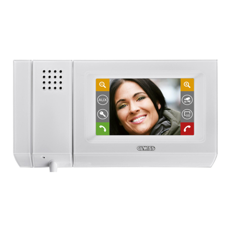
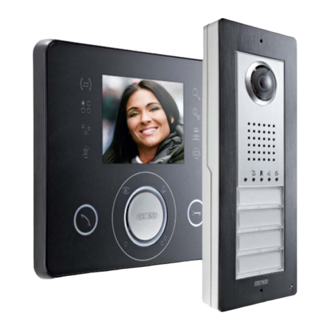
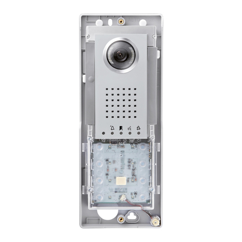
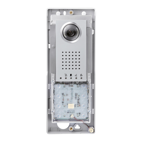
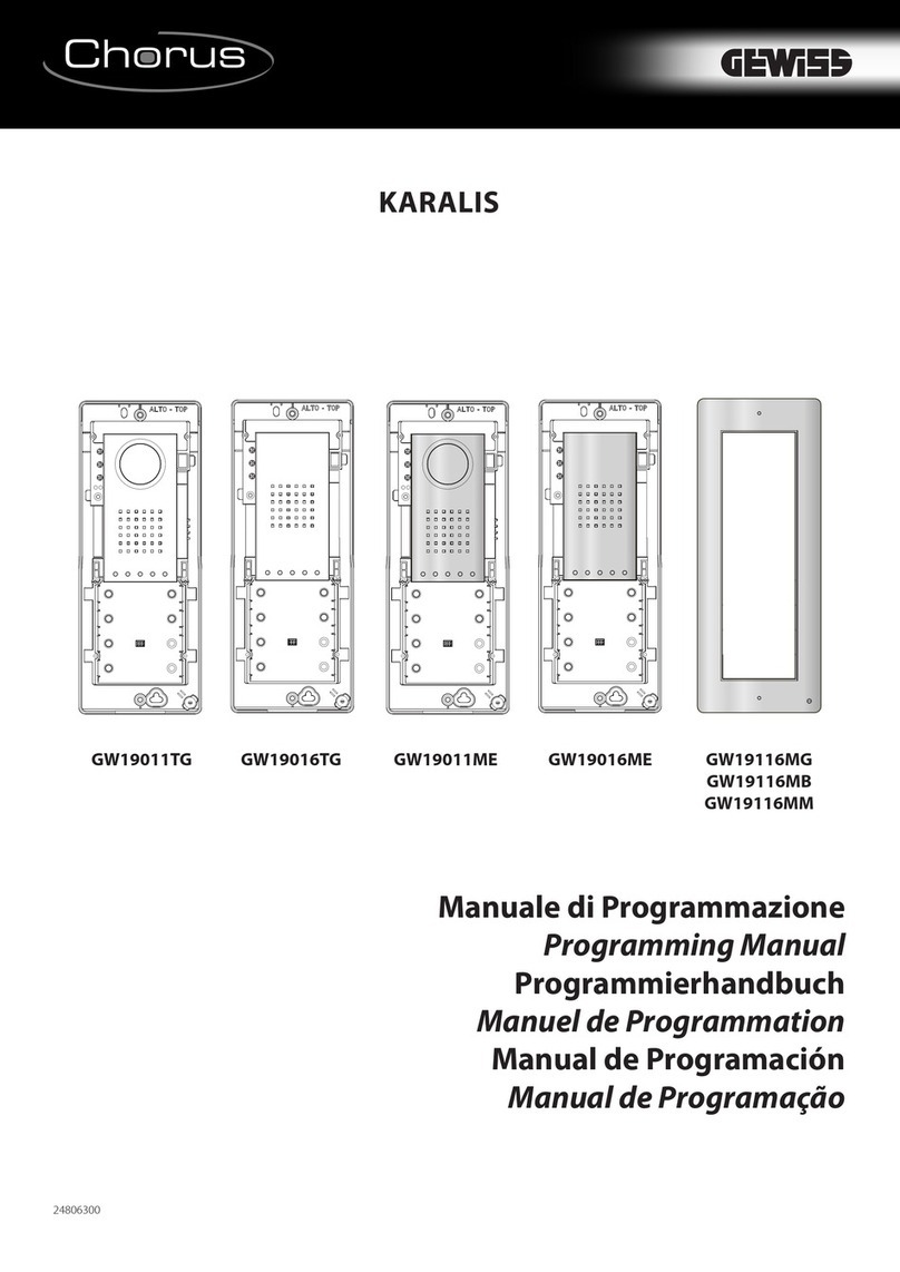
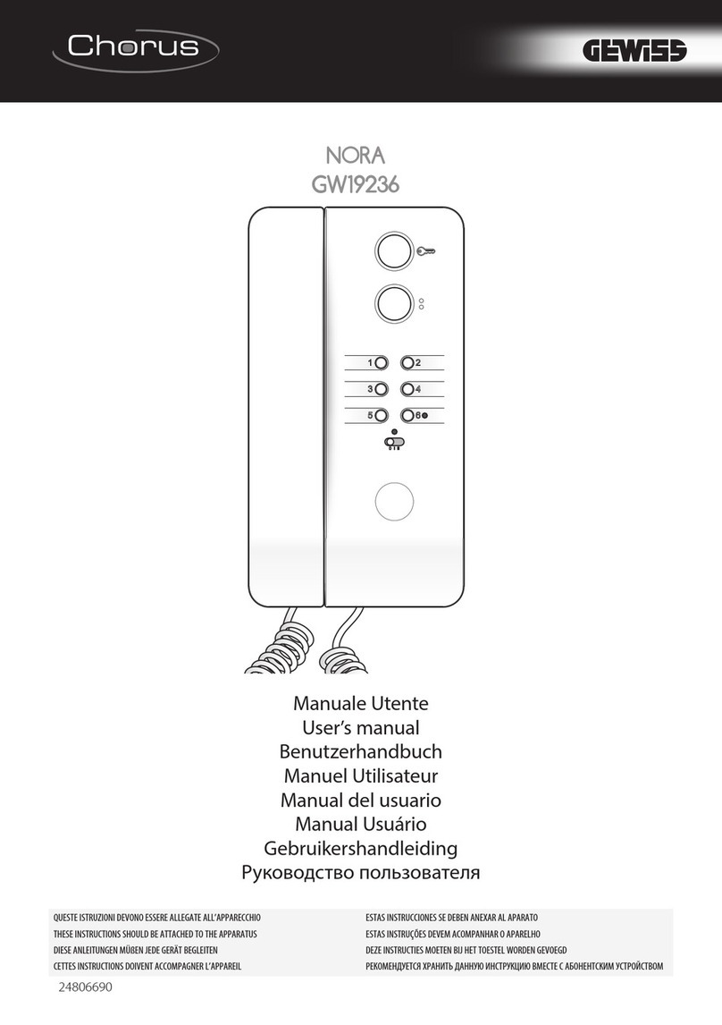
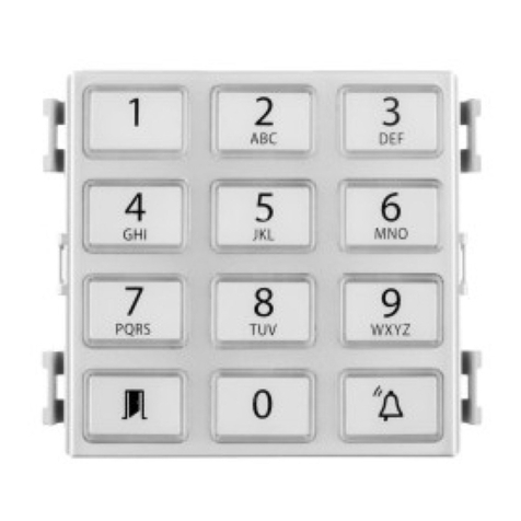
Gewiss Chorus Digital Vision User manual

Video Entryphone Technical Manual

Chorus Digital Vision - Technical System Manualii
Warning! The safety of this appliance is only guaranteed if all the instructions given here are followed scrupulously.
These should be read thoroughly and kept in a safe place. Chorus products can be installed in environments which are dust-free and where no
special protection against the penetration of water is required.
They shall be installed in compliance with the requirements for household devices set out by the national standards and rules applicable to low-
voltage electrical installations which are in force in the country where the products are installed, or, when there are none, following the interna-
tional standard for low-voltage electrical installations IEC 60364, or the European harmonization document HD 60364.
Gewiss sales organization is ready to provide full explanations and technical data on request.
Gewiss and Chorus are trademarks of Gewiss SpA.
The following abbreviations and acronyms may be found in the text and illustrations:
HA Home Automation
IP Internet protocol
LAN Local area Network
FDU Front door unit
AU Apartment unit
PoL Power over LAN
The following graphic symbols may be found in the manual:
Indicates an important safety warning.
Indicates an important warning relating to installation and operation.
Copyright and disavowal of responsibility
`
Abbreviations and graphic symbols used
`

Chorus Digital Vision - Technical System Manual 1
Contents 1
The system 5
General description 5
Functions available 5
System architecture 7
Maximum system expansion 8
System components 8
Devices and accessories for front door units 8
Devices and accessories for apartment units 10
System components 11
Software 13
Design 14
Reference Standards 14
Technology and composition of the video entryphone system 14
Dimensions and maximum extension of the system 15
Positioning the front door unit 16
Positioning the apartment unit 16
Positioning the other system devices 17
Wiring infrastructure 17
The coexistence of electric and data cables (LAN) 17
Cable routes and junction boxes 17
System composition 18
Determining the necessary number of devices 18
Determining the necessary number of switches 19
Determining the necessary number of power supplies 20
Creating the front door unit 20
Combinations for front door units 20
Connection diagrams 23
Single-family video entryphone kit 23
Two-family video entryphone kit 24
Video entryphone system - 160 apartments, 1 upright 25
Video entryphone system - 160 apartments, 7 uprights 27
Video entryphone system with video control cameras 30
Video entryphone system with relay unit 32
Video entryphone system with Vision Master Chorus 34
Installation 37
Wiring 37
Cables that can be used 37
Laying the LAN cable 37
Terminating the cable with an RJ45 connector 37
Video cables 39
Connecting the video entryphone devices 39
LAN network 39
Apartment with several apartment units 41
Front door unit modules 41
Vision Master Chorus 42
Signal extension and long distances 43
Powering the devices 44
Connecting the outdoor devices 45
Apartment unit 45
Front door unit 46
Telecameras 48
CONTENTS

Chorus Digital Vision - Technical System Manual2
Assembling the front door units 49
Assembling and fixing the front door unit boxes 49
Assembling the module-holder frame and suspension cords 50
Assembling the apartment units 52
Assembling Vision Master Chorus 52
Assembling the flush-mounting video entryphone 53
Assembling the wall-mounting video entryphone 53
Assembling the entryphone with speakerphone 54
Assembling the wall-mounting entryphone 54
Configuration 56
Configuration operations 56
Configuration with PC and manual configuration 56
System layout and identification of the devices 56
Customising the devices 57
Audio/video module for front door unit (GW 18 301, GW 18 302) 57
Audio module for front door unit (GW 18 311, GW 18 312) 59
4 push-button module for front door unit (GW 18 321) 59
Vision Master Chorus (GW 18 000 xx) 60
Video entryphone with speakerphone - flush-mounting and wall-mounting (GW 18 341) 60
Entryphone with speakerphone - flush-mounting (GW 18 350, GW 18 352, GW 18 354) 60
Wall-mounting entryphone (GW 18 360) 61
Ethernet switch - DIN rail (GW 18 371) 62
Camera interface - DIN rail (GW 18 376) 62
Relay unit - DIN rail (GW 18 381) 63
Logic connections between front door units and apartment units 64
Adjustments and calibrations 66
Orientating the telecamera of the audio/video module for front door unit 66
Adjusting the volume of the front door unit 67
Configuring the call module with electronic index 67
Adjusting the Vision Master Chorus parameters 67
Adjusting the sensitivity of the Vision Master Chorus echo canceller 67
Video entryphone 68
Completing the front door units 68
Inserting name labels in the push-button panels 68
Inserting the street number label 69
Testing and initial start-up 70
Testing procedure 70
Checking calls from front door units 70
Checking the apartment units 70
Initial start-up 70
Maintenance 71
Inserting new devices in an existing system 71
Adding a new primary or secondary front door unit 71
Adding a new apartment unit 71
Adding a camera interface or relay unit 71
Expanding the front door unit with a 4 push-button module 71
Expanding the front door unit with a street number module 71
Reducing an existing system 72
Removing a secondary front door unit manually 72
Removing a secondary front door unit via PC 72
Removing an apartment unit manually 72
Removing an apartment via PC 72
Removing a camera interface or relay unit manually 73
CONTENTS

Chorus Digital Vision - Technical System Manual 3
CONTENTS
Removing a camera interface or relay unit via PC 73
Replacing faulty devices 73
Replacing the main front door unit module manually 73
Replacing the main front door unit module via PC 73
Replacing the 4 push-button module of the front door unit 74
Replacing the call module with electronic index of the front door unit 74
Replacing the street number module of the front door unit 74
Replacing the power supply unit 74
Replacing the Ethernet switch 74
Replacing the Ethernet 6-port LAN switch 74
Replacing the camera interface or relay unit manually 75
Replacing the apartment unit (any type) manually 75
Replacing the apartment unit (any type) via PC 76
Cleaning 76
Reset procedures 76
Resetting the video entryphone 76
Resetting the wall-mounting entryphone 76
Resetting the entryphone with speakerphone 76
Troubleshooting 77
Preliminary check 77
Identifying and solving an operating problem 78
Possible problems with the apartment unit 78
Possible problems with the front door unit 79
Possible problems with the power supply unit 80
Possible problems with the Ethernet switch 80
Possible problems with the relay unit 81
Possible problems with the camera interface 81
Possible problems with the LAN cable 81
Technical characteristics 82
Technical data 82
Vision Master Chorus (GW 18 000 TB - GW 18 000 VT - GW 18 000 VA) 82
Audio/video module for front door unit (GW 18 301) 83
Audio/video module with 2 push-buttons for the front door unit (GW 18 302) 83
Audio module for front door unit (GW 18 311) 84
Audio module with 2 push-buttons for the front door unit (GW 18 312) 84
4 push-button module for front door unit (GW 18 321) 85
Call module with electronic index for front door unit (GW 18 322) 85
Module with street number for front door unit (GW 18 331) 86
Video entryphone with speakerphone - flush-mounting and wall-mounting(GW 18 341 TB - GW 18 341 VT - GW 18 341 VA - GW
18 343 TB - GW 18 343 VT - GW 18 343 VA) 87
Entryphone with speakerphone - flush-mounting (GW 18 350, GW 18 352, GW 18 354) 88
Wall-mounting entryphone (GW 18 360) 89
Single audio/video power supply unit - DIN rail (GW 18 361) 90
Multiple audio/video power supply unit - DIN rail (GW 18 362) 90
Ethernet switch - DIN rail (GW 18 371) 91
Ethernet 6-port LAN switch - DIN rail (GW 38 371) 92
Camera interface - DIN rail (GW 18 376) 93
Relay unit - DIN rail (GW 18 381) 94
Dimension tables 95
Vision Master Chorus (GW 18 000 TB - GW 18 000 VT - GW 18 000 VA) 95
Video entryphone with speakerphone - flush-mounting and wall-mounting
(GW 18 341 TB - GW 18 341 VT - GW 18 341 VA - GW 18 343 TB - GW 18 343 VT - GW 18 343 VA) 96
Wall-mounting entryphone (GW 18 360) 96

Chorus Digital Vision - Technical System Manual4
Flush-mounting boxes for front door unit (GW 18 131, GW 18 132, GW 18 133) 97
Wall-mounting boxes with rainproof roof for front door unit (GW 18141, GW 18142, GW 18143) 97
Metal frames for front door unit - titanium or slate colour (GW18101VT, GW18102 VT, GW18103 VT, GW18101 VA, GW18102 VA,
GW18103 VA)
98
Frames for front door unit (GW 18 121, GW 18 122, GW 18 123) 98
Flush-mounting box for video entryphone (GW 24 237) 99
Flush-mounting box for Vision Master Chorus (GW 24 101) 99
Flush-mounting box for entryphone with speakerphone (GW 24 403) 100
CONTENTS

Chorus Digital Vision - Technical System Manual 5
Digital Vision is the video entryphone system on IP technology integrated - from a design and practical viewpoint - with the Chorus
devices (domestic range for electric and Home Automation systems). The video entryphone devices are connected to each other via a LAN
network that also provides the necessary power supply (PoL – Power over LAN). This means you can create a wide range of systems,
from the detached home to the medium-sized block of flats.
The range of system devices covers all needs, from simple vocal communication to colour video entryphones, from intercom communica-
tions to video control and integration with KNX domotic systems. The apartment units can be made up of different combinations of video
entryphones, entryphones with speakerphone, and wall-mounting entryphones.
The system is programmed via a PC equipped with the special software, allowing you to configure the entire video entryphone system quic-
kly and easily. Alternatively, for small/medium systems there is also a simplified procedure that does not require the use of a computer.
Call: this allows a call to be made from the front door unit to the apartments linked with that position. If there is a video function, this
is immediately activated along with the call, while the choice of whether to enable the 2-way audio communication is left to the person
called. If the apartment already has a communication in progress, or has activated the Privacy function, the front door unit will indicate the
"busy" status. The person calling may also record a video message after the call, if the Video mail function is enabled.
Privacy: the system can manage several calls and communications simultaneously, yet keeping them entirely separate.
Multiple apartment units: in each apartment, more than one apartment unit can be installed, using the combination of devices you
require.
Primary and secondary front door units: this distinction allows you to subdivide the front door units in a logical manner (for example a
street entrance position and a building entrance position), and also to use different ringers to identify where the call is coming from. The
electro-lock of the primary position can also be activated without any incoming call.
Intercom: direct communications can be made between the apartment units of a single apartment, and (if configured) between the
apartment units of different apartments. The intercom function between different apartments is only possible with audio/video apartment
units (GW 18 341xx, GW 18 343xx, GW 18 000xx).
Video surveillance: on the video entryphone, it is possible to see the images filmed by the telecameras of the front door units, even
without any incoming call in progress, or those filmed by other telecameras connected to the video entryphone system via the camera
interface (GW 18 376).
Identifying the calls: different tones can be used to distinguish the type of call, for example from a front door unit, from the landing, or intercom.
Adjustable volumes: the volume of the communications and buzzers can be adjusted.
Electro-lock: different types of electro-lock can be activated, connecting them directly to the front door units or using the relay unit (GW
18 381). The electro-locks can only be activated from the apartment units in response to a call, or in "free" mode (without an incoming
call). In the case of a call, the system recognises which front door unit it is coming from and activates the relative electro-lock.
"Door open" alarm: some electro-lock models are equipped with a sensor that detects when the door is open, and this information can
be used to inform the video entryphones that the entrance door is not closed.
Auxiliary implementations: thanks to the relays of the apartment units/front door units and relay units, it is possible to command other
systems of the building, such as lights on stairs or access pathways.
Local push-buttons: external push-buttons can be connected to the apartment units/front door units and relay units, to create functions
such as the landing call or door opener.
Internal number busy: the system indicates to the person calling if the internal number is already busy with another communication.
Privacy: by activating this apartment unit function, any incoming call will automatically obtain the "busy" signal and the occupant will not
THE SYSTEM
`General description
Functions available
`
Chorus Digital Vision - Technical System Manual6
THE SYSTEM
be disturbed.
Call transfer:it is possible to transfer incoming calls to another apartment or to the video mail.
Free hands: the apartment unit (video entryphone) can be configured to respond automatically to the call, without needing to press any
keys.
Baby monitoring: this function allows you to monitor what is happening in the room where another video entryphone is installed; only the
devices of the same apartment can be activated.
Office: the opening of the electro-lock can be automatically activated when a call is received during the time bands specified. This fun-
ction cannot be activated if the office has installed both video entryphones and wall-mounting entryphones.
Video mail: if enabled, this allows the person calling from a front door unit to leave a 30-second video message that can subsequently be
viewed on the video entryphone of the apartment called.
Concierge service: using a PC equipped with the porter's desk software (GW 18 392), is possible to receive calls from the apartment
units(*) and front door units, make calls to each apartment unit(*), activate auxiliary services (electro-locks, lights, etc.), activate the video
control, and set the Night&Day operating mode to transfer calls from the front door units to the porter's desk.
(*) The porter's desk software can only be used with audio/video apartment units (GW 18 341xx, GW 18 343xx, GW 18 000xx).

Chorus Digital Vision - Technical System Manual 7
THE SYSTEM
System architecture
`
Apartment unit
Up to 4 apartment unit can be
installed in each apartment.
Ethernet switch
Makes it possible to amplify / distribute the
audio/video signal and supply electric power
to the connected devices.
Intercom function
Integrated in the
devices without
dedicated accessories.
It allows intercommu-
nicating communica-
tions possible between
apartment units in the
same apartment or in
different apartments.
Relay unit
Adds 4 relay contacts to the system for
managing auxiliary loads and 1 output
for impulsive discharge electro-locks.
Telecamera
It records the images of the public
areas where it is installed. It is
powered separately.
Camera interface
It makes it possible to connect the video
surveillance telecameras in common areas,
whose images can be displayed on one or
more apartment units.
Power supply
Supplies power to the devices
connected to the Ethernet switch.
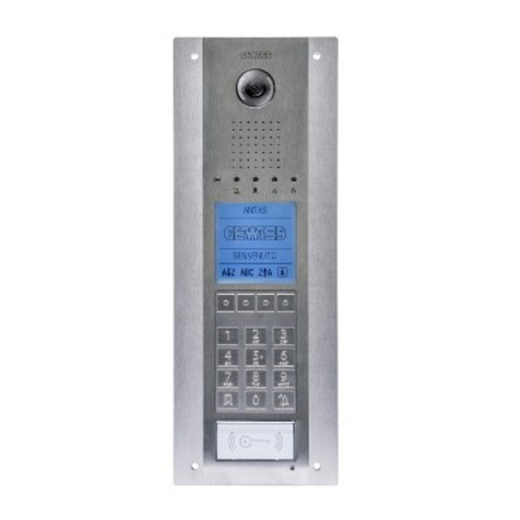
Front door unit
Makes it possible to call
and communicate with
a specific apartment
unit. Available in colour
audio/video or audio
only versions, selecting
the called position
using push-buttons or
an electronic index. For
wall-mounting or
flush-mounting
installation.
UPRIGHT
towards
other Ethernet
switches
Vision Master Chorus
Implements the apartment unit functions. If used
with an Internet Gateway, it displays the supervision
pages for the KNX system.

Chorus Digital Vision - Technical System Manual8
The video entryphone system configured with the aid of a PC can include up to:
t8 front door units
t160 separate apartments
t4 apartment units per apartment
t4 relay units - DIN rail (GW 18 381)
t4 camera interfaces - DIN rail (GW 18 376)
Without the aid of a computer (using the simplified programming procedure), it is possible to install systems of up to:
t2 front door units (one primary and one secondary)
t34 separate apartments
t4 apartment units per apartment
t1 relay unit - DIN rail (GW 18 381)
t1 camera interface - DIN rail (GW 18 376)
Devices and accessories for front door units
Audio/video module for front door unit (GW 18 301)
This main module allows you to create the front door units of the video entryphone system, located for
example at the entrance to the building or individual staircases. It allows a 2-way audio communication
with the visitor, and films the area in front of the front door unit itself. The colour telecamera has a fixed
lens, automatic exposure adjustment, and white LEDs for night-time vision or when visibility is poor.
The speaker volume can be adjusted by means of the potentiometer. The module has an output for
an electro-lock, a relay output for external loads, an input for a local external push-button (local gate
opener), and an input to detect the open status of the electro-lock.
Audio/video module with 2 push-buttons for front door unit (GW 18 302)
The same characteristics as the Audio/video module for front door unit (GW 18 301), plus 2 additio-
nal push-buttons with name plate (backlit with a white light) for calling two separate apartments.
Audio module for front door unit (GW 18 311)
The same characteristics as the Audio/video module for front door unit (GW 18 301), but without the
telecamera.
THE SYSTEM
Maximum system expansion
`
System components
`

Chorus Digital Vision - Technical System Manual 9
Audio module with 2 push-buttons for front door unit (GW 18 312)
The same characteristics as the Audio module for front door unit (GW 18 311), plus 2 additional push-
buttons with name plate (backlit with a white light) for calling two separate apartments.
4 push-button module for front door unit (GW 18 321)
This auxiliary module, which must be used together with the audio/video module (GW18301 or GW 18
302) or the audio module (GW 18 311 or GW 18 312), allows you to add call push-buttons in the front
door units of the video entryphone system. The front door unit can include up to 8 modules of this type.
Each module has 4 push-buttons with a backlit name plate for calling the apartments.
Call module with electronic index for front door unit (GW 18 322)
This auxiliary module, which must be used together with the audio/video module (GW18301) or the audio
module (GW 18 311), allows you to create the front door units of the video entryphone system in structu-
res with a high number of apartments, or when - for lack of space or design reasons - you cannot (or do
not want to) install the modules with the 4 push-buttons (GW 18 321) needed. Each front door unit can
have a single call module with electronic index.
The module has a backlit single-colour LCD screen for viewing the index. By means of the 5 keys and
simple menus, the visitor can choose and call the required name or apartment.
To configure the call module, you must use a PC with the special system configuration software.
Module with street number for front door unit (GW 18 331)
This auxiliary module allows you to complete the front door units of the video entryphone system with
the street number or staircase name/number. The module is backlit by a LED.
Blank module for front door unit (GW 18 332)
This auxiliary module allows you to complete the front door units, closing off the unused module spa-
ces.
Flush-mounting boxes for front door unit (GW 18 131, GW 18 132, GW 18 133)
Boxes for the flush-mounting assembly of the front door unit. Available for one (GW18131), two
(GW18132) or three (GW18133) modules. Up to 3 boxes can be combined (for a maximum of 9
modules), using the special coupling elements supplied.
THE SYSTEM

Chorus Digital Vision - Technical System Manual10
THE SYSTEM
Wall-mounting boxes with rainproof roof for front door unit (GW 18141, GW 18142, GW 18143)
With these, the front door unit can be installed on a wall or other type of support without needing to
make any opening in the wall. Available for one (GW18141), two (GW18142) or three (GW18143)
modules.
Frames for front door unit (GW 18121, GW 18122, GW 18123)
These allow the modules to be fixed in the boxes. They have a hinged joint and suspension cords
so the modules can be easily connected. Available for one (GW18121), two (GW18122) or three
(GW18123) modules. The frame must be chosen on the basis of the box used.
Metal frames for front door unit - titanium or slate colour
(GW18101VT, GW18102 VT, GW18103 VT, GW18101 VA, GW18102 VA, GW18103 VA)
These complete the front door unit. Available for boxes with one (GW18101 xx), two (GW18102 xx) or
three (GW18103 xx) modules.
The last letters of the product code indicate the colour of the finish plate: VT = titanium, VA=slate.
Devices and accessories for apartment units
Vision Master Chorus (GW 18 000 TB, GW 18 000 VT, GW 18 000 VA)
Colour touchscreen panel which, when combined with an Internet Gateway (GW 90
816), acts as an apartment unit and allows you to view the graphic pages for the com-
mand and supervision of the KNX Home & Building Automation system.
The video entryphone functions are managed by simulating - on the screen - the appe-
arance and keys of a video entryphone with speakerphone.
Vision Master Chorus has 2 USB ports (that can be accessed from the outside) for con-
necting a keyboard and mouse.
The last letters of the product code indicate the colour of the finish plate: VT = titanium,
VA = slate, TB = white.
Video entryphone with speakerphone - flush-mounting and wall-mounting (GW 18 341 TB, GW 18
341 VT, GW 18 341 VA flush-mounting / GW 18 343 TB, GW 18 343 VT, GW 18 343 VA wall-mounting)
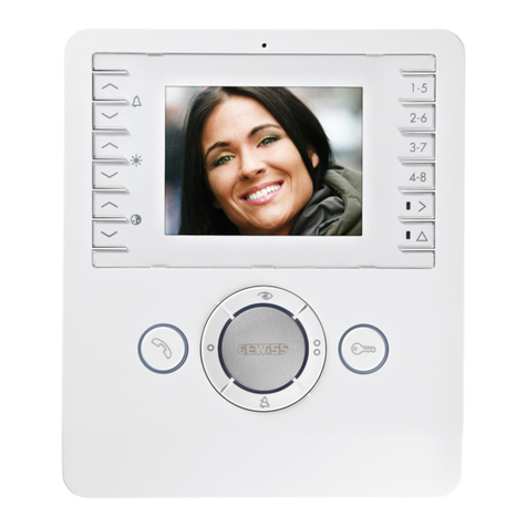
The video entryphone allows you to establish a 2-way audio communication with the person calling, and
reproduces - on the colour LCD screen - the images filmed by the Audio-video module for front door unit
(GW18301, GW 18 302) or by the control telecameras connected to the video entryphone system.
If not used, the screen switches off automatically after the set standby time.
The video entryphone has 6 command push-buttons that allow you to perform the most common
actions directly (e.g. respond to a call, open the door). They can also be used to access the menu and
enable the advanced functions or customise the use of the device.
The video entryphone has an input for a local push-button (call from landing) and a relay output for a
local implementation.
The last letters of the product code indicate the colour of the finish plate: VT = titanium, VA=slate, TB = white.

Chorus Digital Vision - Technical System Manual 11
Entryphone with speakerphone - flush-mounting (GW 18 350, GW 18 352, GW 18 354)
The entryphone allows you to establish a 2-way audio communication with the person calling. The de-
vice has 4 push-buttons (touch) for accessing the functions of response, electro-lock command to front
door units, intercom call with another three apartment units, and privacy. The latter function deactivates
the call buzzer from both front door and apartment units. The entryphone has 5 LEDs to indicate the
indoor intercom position selected, and for the privacy function.
Wall-mounting entryphone (GW 18 360)
The wall-mounting entryphone allows you to establish a 2-way audio communication with the person
calling.
The device has 7 push-buttons (touch) for accessing the functions of response, electro-lock command,
intercom call with another three apartment units, privacy, and ringtone adjustment.
The wall-mounting entryphone has an input for a local push-button (call from landing) and a relay
output for a local implementation.
Flush-mounting box for video entryphone (GW 24 237)
Box for the flush-mounting assembly of the flush-mounting video entryphone (GW 18 341 XX).
Flush-mounting box for Vision Master Chorus (GW 24 101)
Box for the flush-mounting assembly of Vision Master Chorus (GW 18 000 xx).
Flush-mounting box for entryphone with speakerphone (GW 24 403)
Box for the flush-mounting assembly of the flush-mounting entryphone with speakerphone (GW 18
350, GW 18 352, GW 18 354).
System components
Single audio/video power supply unit - DIN rail (GW 18 361)
This device provides the supply current (SELV - Safety Extra Low Voltage - 14.4V DC rated) to the devi-
ces of the video entryphone system.
It has a single 18 VA output.
THE SYSTEM

Chorus Digital Vision - Technical System Manual12
Multiple audio/video power supply unit - DIN rail (GW 18 362)
The same characteristics as the Single audio/video power supply unit - DIN rail (GW 18 361), but with a
double output (2 x 18 VA).
Ethernet switch - DIN rail (GW 18 371)
The device makes it possible to connect the various devices of the video entryphone system together,
enabling audio, video and data communication and distributing the electric power supply to the devices
themselves, as needed, via the PoL ports.
The power supply current (SELV - Safety Extra Low Voltage - 14.4V DC rated) is supplied to the switch
from the audio/video power supply unit (GW 18 361 or GW 18 362).
The switch has two standard Ethernet LAN ports and 4 PoL Ethernet LAN ports (Power over LAN, device
power supply through the LAN cable), which can be reconfigured as standard by disabling the PoL
power supply using the relative slide-type switch.
Ethernet 6-port LAN switch - DIN rail (GW 38 371)
The same characteristics as the Ethernet switch - DIN rail (GW 18 371), but without the possibility to
configure the ports as PoL (Power over LAN, whereby the device is powered via a LAN cable).
Camera interface - DIN rail (GW 18 376)
This device allows you to complete the video entryphone system with PAL or NTSC analogue telecame-
ras in order to create a video control system.
The analogue video signal of the telecameras is converted into a digital signal by the camera inter-
face, so it can then be transmitted via the LAN video entryphone network and display the images on
any video entryphone with speakerphone (GW18 341 xx, GW 18 343 xx) or Vision Master Chorus (GW
18000 xx).
THE SYSTEM

Chorus Digital Vision - Technical System Manual 13
Relay unit - DIN rail (GW 18 381)
This device allows you to complete the video entryphone system with additional relays for commanding
general electric loads, and an additional electro-lock.
Each relay unit is equipped with:
tSFMBZPVUQVUTtJOQVUTGPSUIFMPDBMDPNNBOEPGUIFSFMBZPVUQVUTtPVUQVUGPSUIFFMFDUSPMPDLtJOQVUGPSUIFMPDBMDPNNBOEPGUIFFMFDUSPMPDLtJOQVUGPSEFUFDUJOHUIFPQFOTUBUVTPGUIFFMFDUSPMPDLThe outputs can be activated from the apartment units or using the push-buttons connected to the
inputs. The contact closure time is timed, for each individual output, by rotary selectors.
LAN UTP network cable, cat. 5e, for indoor wiring (GW 38 189)
Wire in solid copper 24 AWG, external sheath in LSZH, external diameter 5.3mm.
LAN UTP network cable, cat. 5e, for outdoor wiring (GW 38 195)
Wire in solid copper 24 AWG, double sheath in PVC - PE, external diameter 7.2mm.
Software
Porter's desk software (GW 18 392)
This software allows you to implement - with the aid of a PC - a concierge enclosure for the video
entryphone system. The main functions obtained are:
treceiving a call from the front door unit
tforwarding a call to the apartment
tvideo control
tactivating the contacts of the relay units
GW-VCT Configurator
GW-VCT Configurator is the software for the initial start-up of the video entryphone system. This sof-
tware allows you to create the logic connection between the various system devices, without any need
for the manual procedure.
The main functions are:
tthe automatic recognition of the devices connected to the system (front door and apartment units,
relay units and camera interfaces).
tthe selective search for the devices
tthe automatic creation of the intercom call inside the apartment
tthe configuration of the front door units
tthe customisation of the names in the electronic index
tthe customisation of the device identification elements
tthe synchronisation of the time/date on the video entryphones
tthe storage and printing of the project file
The latest version of the software can be downloaded, free of charge, from the website:
www.gewiss.com/irj/portal/gwvct_IT
THE SYSTEM

Chorus Digital Vision - Technical System Manual14
DESIGN
ATTENTION: the devices must only be installed by qualified personnel, observing the current regulations and
the guidelines for video entryphone installations.
By creating the system, it shall be observed the requirements for household devices set out by the national standards and rules applicable
to low-voltage electrical installations which are in force in the country where the products are installed, or, when there are none, following
the international standard for low-voltage electrical installations IEC 60364, or the European harmonization document HD 60364.
The Chorus video entryphone system is a digital system. Audio, video, information and commands are all transferred in the form of data
packages on an IP network.
In its standard form1, a video entryphone system consists of a front door unit, two apartment units, a switch for connecting these devices,
and a power supply unit to provide the 14.4V SELV supply voltage. The devices are connected to each other via Ethernet standard cables.
The power supply arrives directly to the front door units, while for the apartment units it is distributed by the switch, via the Ethernet
cables
(PoL – Power over LAN). The switch has 4 PoL ports, and allows you to connect 4 devices that need to be powered (apartment unit,
camera
interface or relay unit) in whatever combination you prefer. In addition to the PoL ports, the switch has two Ethernet standard
ports (not powered) that can be used to connect front door units, Vision Master, Internet Gateway, a programming PC, or other switches
(to expand the system). If extra LAN standard ports are needed, you can use the switch to disable the power supply on all the PoL ports or,
alternatively, add an Ethernet 6-port LAN switch - DIN rail (GW 38 371).
The switches are connected to each other in cascade form.
The camera interface and relay unit may also be powered from an external power supply unit.
IMPORTANT: the order in which the various devices are connected has no effect on the operation. For example, apartment units
belonging to a single apartment can be connected to different switches, and front door units belonging to different staircases
can be connected to the same switch.
For further information about the connections, refer to the section Connection diagrams and the chapters Types of electrical connections
and Connecting the front door units.
1) In the case of a single-family system, there is another (reduced) configuration requiring only a front door unit, a single apartment unit,
and the power supply unit, but a special cable is needed to connect the front door and apartment units.
Reference Standards:
`
Technology and composition of the video entryphone system
`
Front door
unit
(FDU)
Switch
Power supply
Apartment
unit
(AU)
Apartment
unit
(AU)
SELV power supply
SELV power
supply
Standard Ethernet
PoL Ethernet
PoL Ethernet

Chorus Digital Vision - Technical System Manual 15
DESIGN
Dimensions and maximum extension of the system
When planning the video entryphone system, it is important to bear in mind the following maximum values:
Max. number of front door units 8
Max. number of apartments 160
Max. number of apartment units per apartment 4
Max. number of relay units 4
Max. number of camera interfaces 4
Max. length of LAN cable 100m
Max. length of supply cable between power supply unit and any
other device
100m, with a cable section of 1mm2
Max. number of switches between any two devices 60
Max. length of connection cable for electro-lock opening button 40m, with a cable section of 1mm2
Max. length of connection cable for electro-lock 50m, with a cable section of 1mm2
Max. length of cable for landing call 50m, with a cable section of 1mm2
Max. length of connection cable for electric load / device relay 50m, with a cable section of 1mm2
NB: for further information about how to increase the distance between the devices, refer to Signal extension and long distances.
ATTENTION: for the maximum voltages and currents allowed on the relays, refer to the technical specifications of the individual
devices.

Chorus Digital Vision - Technical System Manual16
The upper side of the front door unit must be about 160-165cm from the
ground.
When using an audio/video module with telecamera, the front door unit must
not be positioned to face strong light sources, or in places where the person is
against the light (for instance, when the person calling has a lamp-post behind
him). A strong background light will, in fact, reduce the brightness and the
contrast of the image because the telecamera adjusts its exposure level to the
brightest areas of the image.
NB: to ensure the person is well-lit in the dark, you are advised to install an
outdoor light source.
If there is no other suitable place for the front door unit, you can try raising it to a height of 180cm from the ground, so the telecamera is
pointing downwards and thereby reduces the back lighting effect.
For further information about the creation of front door units, refer to Combinations for front door units.
For the degree of environmental protection (IP) and the operating temperatures of the front door unit modules, refer to Technical characteristics.
NB: if the front door unit is to be used mainly or wholly by people in wheelchairs, it may be better to install the position at a lower height.
The upper side of the apartment unit (video entryphone, flush-mounting
entryphone with speakerphone, or wall-mounting entryphone) must be about
160-165cm from the floor.
If the apartment unit is a video entryphone, make sure the screen is not hit by
a direct light (sunlight or lamps) as this would reduce the quality of the image
viewed.
If the apartment is inhabited by a person with mobility problems, it is a good
idea to lower the apartment unit to a height of about 120-125cm from the floor;
the standard height (160-165cm) does not prevent the apartment unit being
used by disabled people, but it does make it more difficult for them.
DESIGN
Positioning the apartment unit
`
165 cm
Positioning the front door unit
`
165 cm

Chorus Digital Vision - Technical System Manual 17
The other devices of the video entryphone system must be installed in distribution boards fitted with a DIN rail, or in the Gewiss PTDIN flush-
mounting boxes (for instance GW 48 109). As the PTDIN boxes have a DIN rail, and dividers can be inserted in them, they are ideal when
installing power supplies and switches for the various floors of blocks of flats or other types of building.
ATTENTION: the video entryphone system must be kept separate from any data network of the apartment or block of flats.
The coexistence of electric and data cables (LAN)
The DIGITAL VISION System is based on IP technology, and device wiring is regulated by the same rules applied for so-called “structured wiring”.
In particular, it is known that in certain cases there are no alternatives to using the same cable path for laying the data cable (LAN) and the
energy cable. For example, when restructuring or replacing an old video entryphone system there may be only one cable path available for
connecting the front door unit, and the laying of a new, separate one would involve costly work. This gives rise to the problem of whether
and how the data and energy cables can coexist in a single cable path.
What the regulations say
The regulations specify that certain distances must be maintained between data cables and energy cables, for two distinct reasons:
ŘElectrical safety: for the purposes of electrical safety, the data and energy cables may only be installed in the same cable path (the
same conduit) if the data cable has double insulation. In any case, a LAN cable may coexist with SELV power supply cables (14.4V).
ŘDisturbance immunity: Standard EN50174-2 defines the distance to be maintained when laying energy cables and data cables.This
distance varies according to the shielding of the cables and the presence of a metal divider between the cables: the two cables may only be
laid in the same path (same conduit) if they are both shielded. The table below shows the minimum distances from electric supply lines, as
specified by the above-mentioned standard.
What Gewiss recommends
The Gewiss cables for wiring the DIGITAL VISION system are:
tGW 38 189: LAN UTP cable, cat 5e, for indoor wiring
tGW 38 195: LAN UTP cable, cat 5e, for outdoor wiring, with double insulation.
To ensure the correct functioning of the system, you are advised to lay the DIGITAL VISION system cables and the energy cables in separate cable paths.
If you need to pass the DIGITAL VISION cable and the energy cable in the same path (same conduit), the only Gewiss cable you can use is the
GW 38 195. The double insulation of this cable guarantees electrical safety, but not disturbance immunity. To obtain full disturbance immunity,
it is necessary for both the data and the energy cable to be shielded. If this is not possible, there may be disturbances due to electromagnetic
couplings and this means the optimum quality performance of the system is not guaranteed.
Cable routes and junction boxes
The cable routes can be chosen on the basis of the cables they must contain. Bear in mind that a shielded data cable usually has a diameter
of about 8mm, and a shielded energy cable (with 3 wires with a section of 2.5mm2)has a diameter of more than 15mm.
In addition, the cable routes and junction boxes must prevent the cables being subjected to sharp bends.
DESIGN
Positioning the other system devices
`
Wiring infrastructure
`
Type of cable
Application field: 2kVA - 500V
Without divider With non-metal
divider With metal divider
Non-shielded energy cable
Non-shielded data cable 200mm 100mm 50mm
Non-shielded energy cable
Shielded data cable 50mm 20mm 5mm
Shielded energy cable
Non-shielded data cable 30mm 10mm 2mm
Shielded energy cable
Shielded data cable 0mm 0mm 0mm

Chorus Digital Vision - Technical System Manual18
Determining the necessary number of devices
A video entryphone system consists of:
ta front door unit, situated at the entrance from the street
tin the case of structures with several buildings or staircases, there may be additional (secondary) front door units
tat least one apartment served.
"Apartment" generally refers to a single inhabited unit (apartment, office, shop, etc.) that may be called and that corresponds to a single
push-button of the front door unit.
In every apartment, up to 4 apartment units can be installed, and these are all connected to the same push-button of the push-button
panel.
There is usually only one front door unit in a system, situated at the entrance from the street, but in certain cases (such as accommoda-
tion structures with several buildings or staircases, or buildings with several entrances from the street) there may be more than one.
The front door units on the street must be able to call all the apartments, while the call positions at the entrance to the staircase or indivi-
dual buildings call only the apartments of that particular staircase or building.
A system always has at least one primary front door unit, coinciding with the call position situated at the entrance from the street. The
electro-lock of the primary front door units can be activated even without a call or conversation in progress ("free" mode, to be purposely
activated). Important: if several primary front door units are associated with an apartment unit in "free" mode, the electro-lock command
only acts on the main primary front door unit (the first position programmed).
DESIGN
System composition
`
1 2 3 4 1 2 3 4
1 2 3 4
Apartment B Apartment A
A
B
Front door unit
Logical connections
between a front door unit
and apartment units
Apartment unit
Table of contents
Other Gewiss Intercom System manuals

Gewiss
Gewiss Chorus NAXOS GW19201WH User manual

Gewiss
Gewiss Chorus KARALIS GW19011TG User manual

Gewiss
Gewiss Chorus City Vision VELIA GW19211WH User manual

Gewiss
Gewiss Chorus KARALIS GW19016TG Owner's manual

Gewiss
Gewiss Chorus GW19401WH User manual

Gewiss
Gewiss Chorus City Vision Series User manual

Gewiss
Gewiss CHORUS VELIA GW19216BK User manual

Gewiss
Gewiss Chorus KARALIS GW19137TG User manual

Gewiss
Gewiss Chorus ANTAS GW19061 User manual

Gewiss
Gewiss Chorus NAXOS GW19201WH User manual