Data Logger Instruction Manual
4
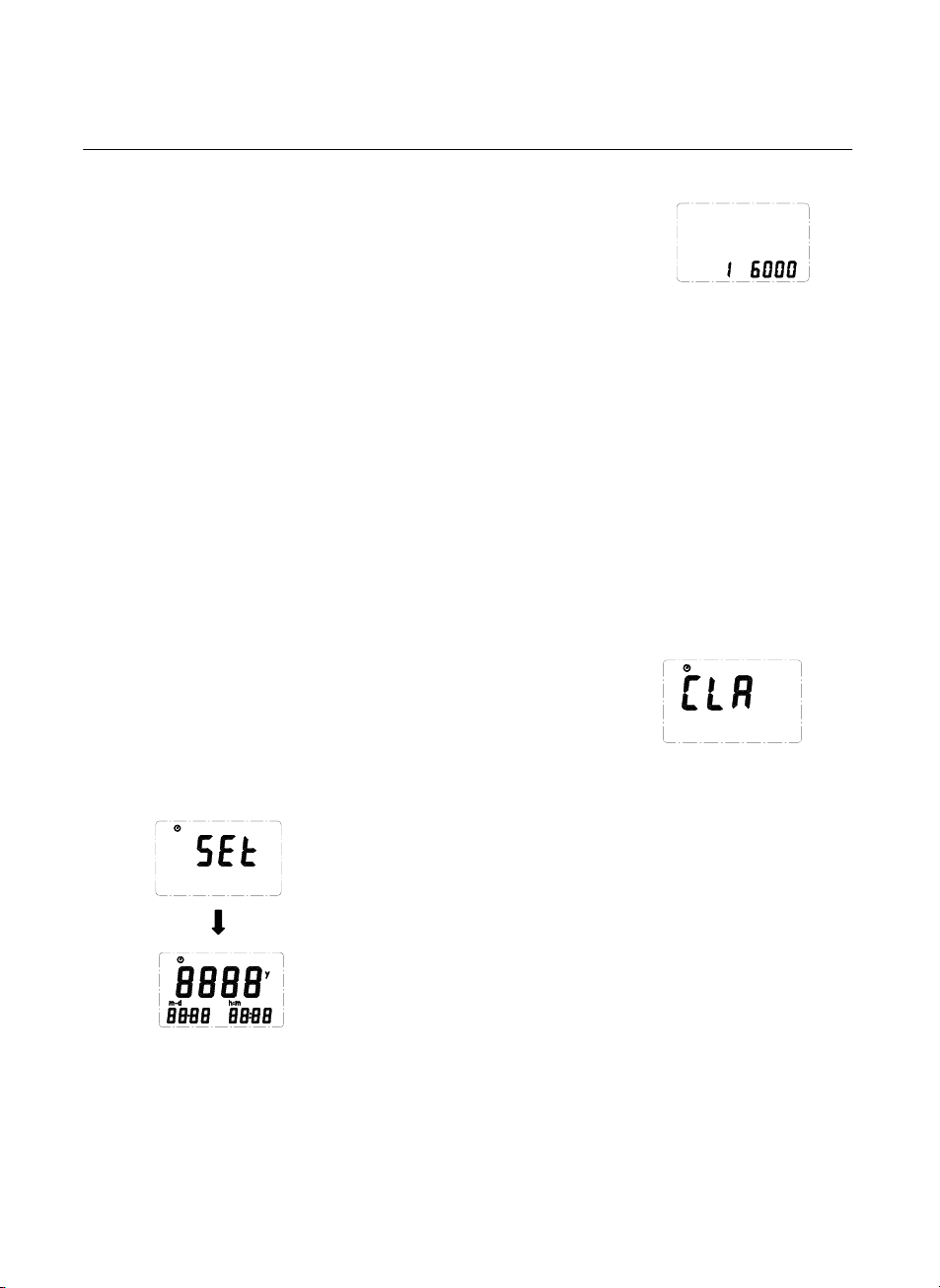
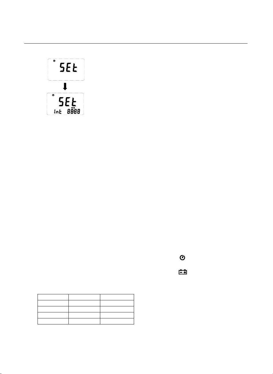
4.7 Recording Interval Setup :
1: press and hold “MAX MIN” button and then power on the meter:
2: press “HOLD"(INTV)
3: press "REC" or "°C/°F" to increase or decrease number,
press “HOLD" (INTV) to adjust next item, then press “HOLD” (INTV)
to finish. If you want abort during a setup process, press power
button to cancel.
4.8 Relative Operation:
When one press the “REL” button, the meter will memorize the present reading and the difference
between the new reading and the memorized data will be shown on the display. Press the “REL”
button again to exit the Relative operation. When the meter is under relative operation, “ °C/°F ”
button is disabled. (when you press “ °C/°F ” button in relative mode, there will be two continuous
beep)
4.9 MAX/MIN Operation:
When one press the "MAX MIN" button the meter will enter the MAX/MIN mode. Under this mode
the maximum value, minimum value is kept in the memory simultaneously and updated with every
new data.
When the MAX symbol is display, the Maximum is shown on the display.
Press "MAX MIN" again, then the MIN symbol is on the display and also the minimum reading.
Press "MAX MIN" again, MAX, and MIN will blink together. This means that all these data is
updated in the memory and the reading is the present temperature.
One may press "MAX MIN" to circulate the display mode among these options.
When the meter is under "MAX MIN" operation, “REL” and “ °C/°F ” button are disabled.(when
you press "REL” and “ °C/°F ” button in "MAX MIN" mode, there will be two continuous beep)
To exit the MAX/MIN mode, one may press and hold "MAX MIN" for two seconds.
4.10 Auto Power Off:
By default, when the meter is powered on, it is under auto power off mode. The meter will power
itself off after 30 minutes if no key operation and no RS232 communication and no recording.
combination at power on can disable auto power off.
One may press and hold “HOLD” button and then power on the meter and there will be two
successive beeps to indicate that auto power off is disabled and the will not show up.
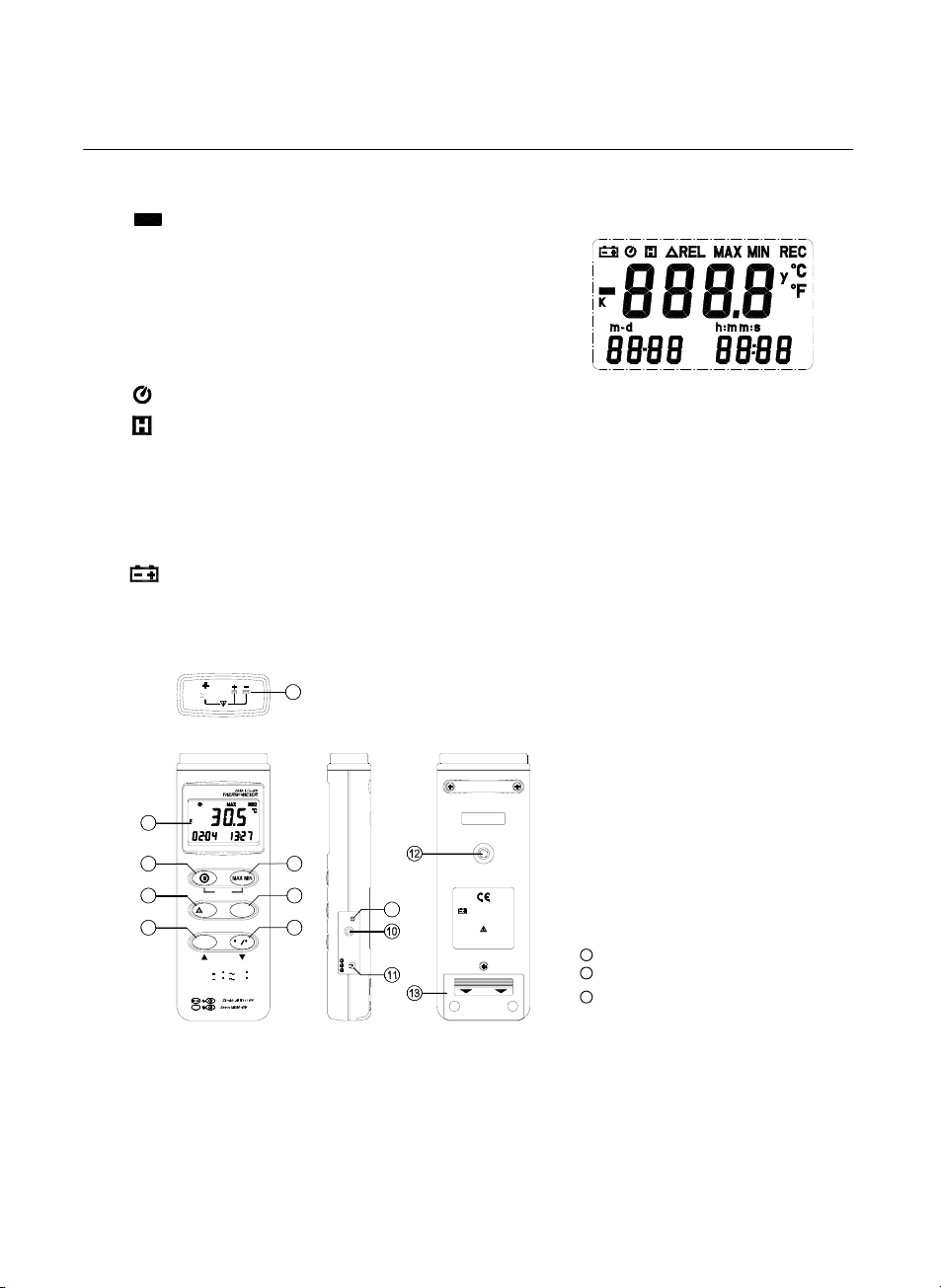
4.11 Low Battery Condition
When the battery voltage is under proper operation requirement, the symbol will show on the
LCD and the battery need to be replaced with new one.
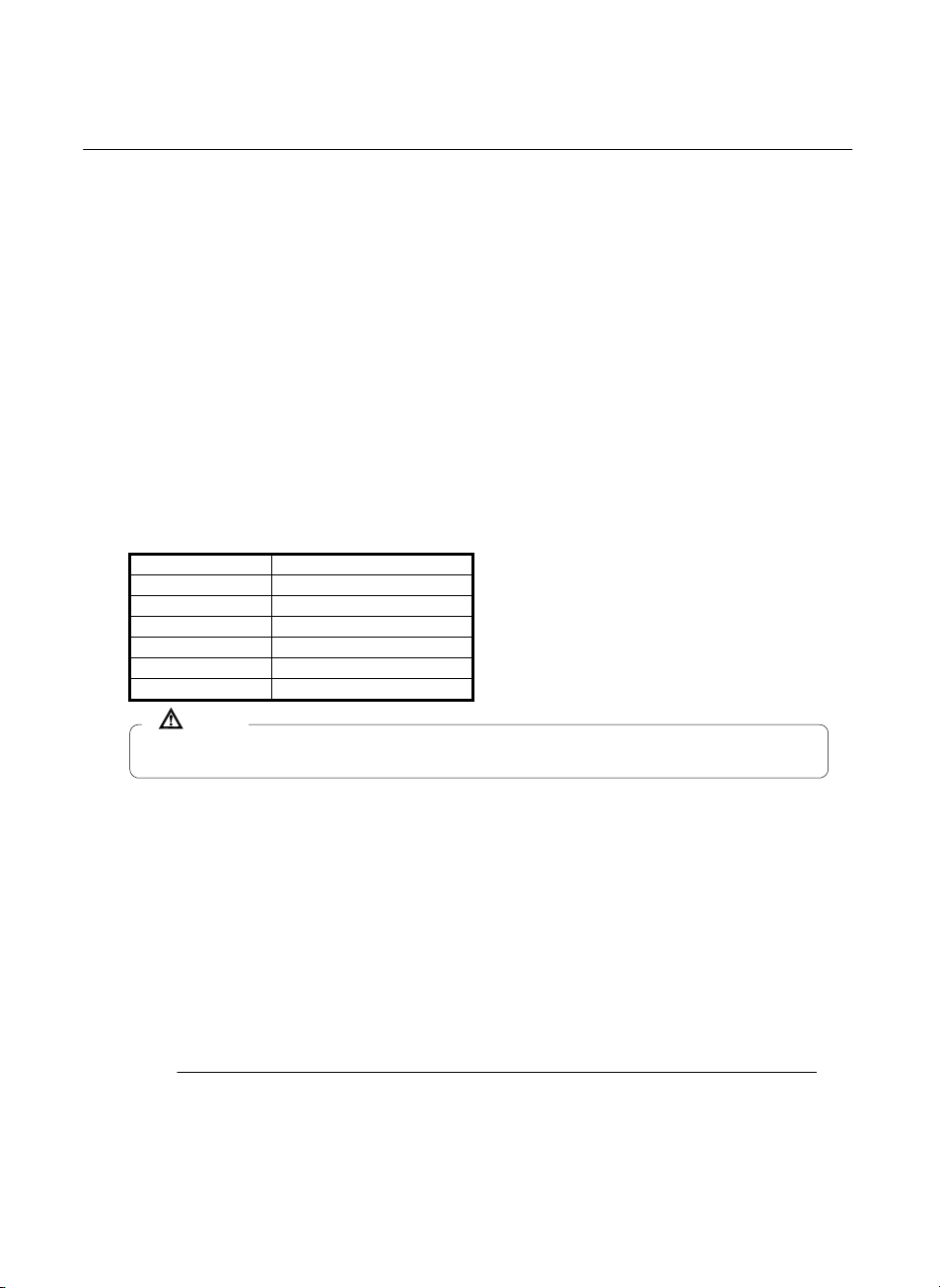
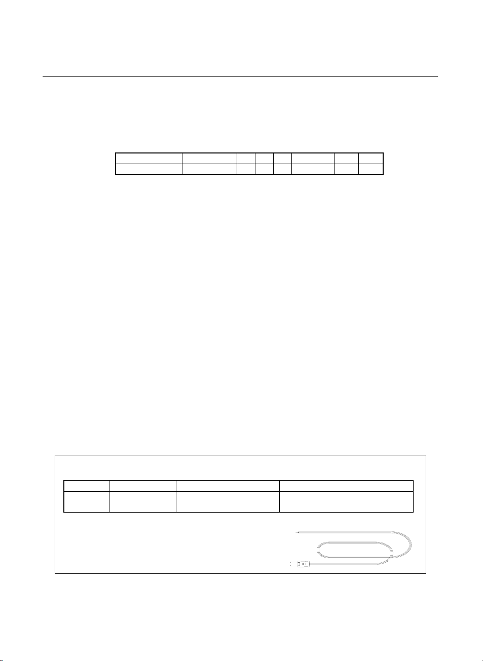
4.12 Calibration Point:
input Adjust VR tolerance
0 °C VR1 ± 0.1 °C
190 °C VR2 ± 0.1 °C
1000 °C VR3 ± 1 °C
1900 °F VR4 ± 1 °F
P. S
Normally, performing offset Calibration with thermal
stabled ice water through VR1 will give a very good
calibration result.