Giada MI-D2700D User manual

www.giadatech.com User’s Manual
MI-D2700D/N2600D
All right reserved
Version 001
Motherboard

21
Gratitude ……………………………………………………………………………
About the product …………………………………………………
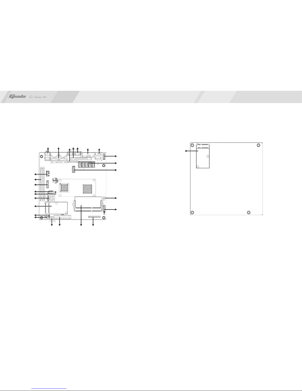
1. Picture of the motherboard ………………………………………………
2. Features ……………………………………………………………………
2.1 Processor ………………………………………………………………
2.2 Memory …………………………………………………………………
2.3 BIOS ……………………………………………………………………
2.4 Interfaces of peripherals ………………………………………………
2.5 Power management …………………………………………………
2.6 Expansion slot …………………………………………………………
Hardware installation ……………………………………………… …
1. Layout of motherboard ……………………………………………………
2. Installing memory …………………………………………………………
3. Install expansion slot card ………………………………………………
4. Motherboard jumper setting ………………………………………………
4.1 SATA0/SATA1 …………………………………………………………
4.2 CPU_FAN1SYS_FAN ………………………………………………
4.3 CLR_CMOS ……………………………………………………………
4.4 F_USB2 ………………………………………………………
4.5 F_AUDIO ………………………………………………………… …
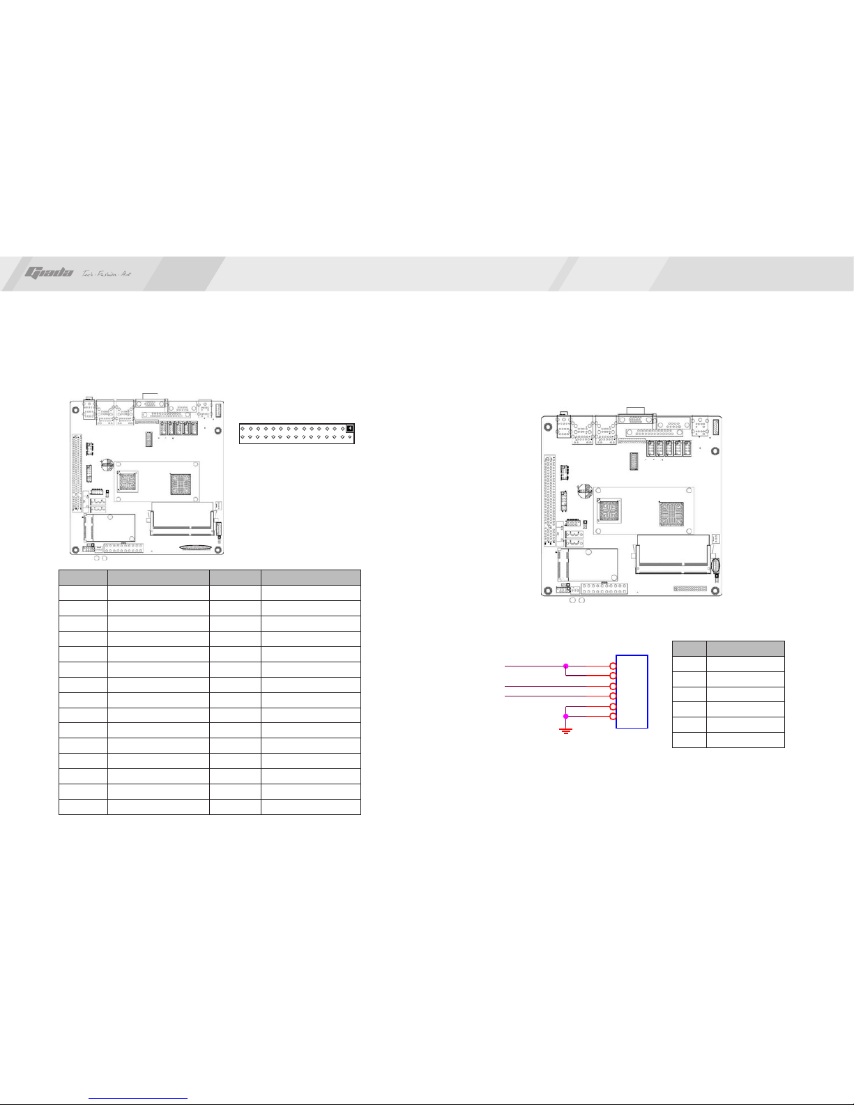
4.6 COM 2-6 Needle inserted definition …………………………………
4.7 JLVDS ……………………………………………………………… …
4.8 GPIO ………………………………………………………………
I……………
II …………
…
………
…
…
……
4.9 VGA out …………………………………………………………
4.10 PS/2 out ……………………………………………………………
4.11 AUTOPW_ON …………………………………………………………
Pin
Pin
Contents
BIOS setting ………………………… …………………………
1. Main menu …………………………………………………………………
2. Main (Standard CMOS Setup) …………………………………………
3. Advanced (Advanced BIOS Setup) ……………………………………
4. Boot Configuration ……………………… ……………………………
5. Security setup ………………… …………………………………………
6. Exit ……………………………………………………… ………
Software installation ………… ……………………………………
1. Install driver for motherboard ……………………………………………
1.1 Install driver for chipset ………………………………………………
1.2 Install sound card driver ………………………………………………
1.3 Install driver for on-board LAN chip …………………………………
2. HD_AUDIO sound card setup ………………………………………
4.12 Power ATX20 Pin ……………………………………………………
4.13 F_ PANEL ……………………………………………………………
5. Rear panel interface ………………………………………………………
I II ……………
……
…
……………
IV …………
……
3
4
5
5
5
5
5
6
7
8
11
11
11
12
16
15
13
17
19
20
21
22
23
4
6
6
33
33
35
www.giadatech.com
2 4
2 6
27
37
28
30
32
20
21
38
10
28
36

4
3
Gratitude I. About the product
www.giadatech.com
NOTE: This is Giada real product photo show for your reference only, Product
appearance depends on goods.
Thank you for choosing Giada motherboard.
®
Giada D2700D/N2600D is based on Intel Atom™Cedar Trail Processor and
NM10 chipset.It supports DDR3 1066 Dual-channel memory, on-board HD-
AUDIO sound card and 2 * 1 gigabit LAN. Support VGA display output and
LVDS display(Max 1440*900)
Any question about the product, please send e-mail to our support center.
Headquarter:
USA office: [email protected]
N2600D
1. Picture of the motherboard
D2700D

6
5
2.1 Processor
·
2.2 Memory
·
·
2.3 BIOS
·
2.4 Interfaces for peripherals
·
2. Features
®
On-board Intel Atom™ Processor D2700/N2600;
Supports 204-Pin DDR3 1066 MHz memories * 1;
4GB at maximum;
Supports PNP, APM and ATAPI;
Supports ACPI;
Automatic detection and supporting hard disk whose LBA mode is over 160G;
End-users can easily upgrade the motherboard with BIOS;
Two SATA2 HDD port;
One LPT interface;
One VGA interface;
Eight USB2.0 ports / Pin out which are compatible with USB1.1;
Two RJ45 network interface (PCIe Gigabit Ethernet);
On-board HD-AUDIO audio adapter;
Interfaces on panels can be compatible with HDD LED, Speaker, etc;
One CMOS contact pin;
One system FAN socket;
Six com port / Pin out;
·
·
·
·
·
·
·
·
·
·
·
·
II. Hardware installation
www.giadatech.com
Warning
·
The motherboard consists of a great number of ICs and other components. These
ICs might be damaged by the static charge. Therefore, the user must make the
following preparations before installation:
Turn off the power of the computer. It is preferable the power cord be unplugged.
Take care not to contact the metal wires and theirs joints on the motherboard
when handling it.
It is preferable that the operator wear the anti-static wrist strap when handling
the IC components.
Before the ICs are installed, the components of the motherboard should be
placed on the anti-static mat or bag.
When you remove the plug on the DC-IN power supply of the motherboard,
make sure the switch of the power supply is in OFF state.
Installing the motherboard onto the computer case:
For most of the computer cases, the multiple fixing holes left on their bottoms can
be used for securing the motherboard and preventing short circuit. During your
operation, take care not to allow the screws to contact any circuit or part on PCB.
When circuits on the surface of the motherboard get close to the fixing holes, you
can use the plastic sheet to separate the screws from the board surface so as to
avoid damage or failure of the motherboard.
·
·
·
·
2.5 Power management
·
·
2.6 Expansion slot
· Two MINI-PCIe slots.
Support APM and ACPI;
Compatible with energy star “Green PC”.

8
7
1. Layout of motherboard
www.giadatech.com
1 COM 1
2. VGA
3. LPT
4. VGA Pin Out
5. RJ45+USB
6. AUDIO_OUT
7. F_AUDIO
8.
9. USB+IR
.
PCI
10. USB
11. CMOS
12. SATA 0,1
13. MINI-PCIE
14. AUTOPW_O
15. F_PANEL1
16. SYS_FAN
17. ATX 20PIN
18. DDR3
19. JLVDS
20. JLVDS POWER
21.CPU_FAN
22.GPI
23.COM 2-6
24.PS/2 Pin out
25.PS/2
26.MINI_PCIE
1
2
4
7
10
17 18 19
22
5
20
16
3
6
8
9
11
12
13
14
15
21
23
24
25
2. Installing memory
Please install the memory in accordance with the following procedures:
· Align the golden finger of the memory to the groove of the interface slot and
pay attention the concave hole of golden finger should be aligned to the
convex point of the slot.
26
背 面
正 面

10
9
www.giadatech.com
3. Install expansion slot card
Installing Mini-PCIE extended devices
At the rear panel of motherboard is two Mini-PCIE extended slots, to which the
user can connected WIFI module and Bluetooth module etc.
If the user use a module type mSATA on slot 2, then can just use SINGLE
SATA HDD since MI-PCIE2 share same signal with SATA1.
· Finally, insert the memory into the interface slot gently. If no error occurs at
the moment, insert the card forward in the slot till the white buckle is
automatically engaged in the concave hole at the two sides of the memory.
NOTE: In order to avoid damages to the motherboard or the components, the
user must make sure the power supply to the computer is turned off before the
memory or other component is installed or removed. As the groove is set at the
golden finger of the DDR DIMM, the memory can only be inserted into the slot
with one direction. During installation, the user only needs to align the golden
finger and the dual-channel groove of the interface slot and insert it gently. To
avoid damage, never apply excessive force in that process.

11
4.2. CPU_FAN1 SYS_FAN(CPU FAN socket)
This receptacle can be used for connecting CPU/system fan. Its pins are
defined below. The user shall make sure the fan is conforming.
PIN
1
2
3
Definition
GND
12V
SIGNAL
www.giadatech.com
123
12
PIN Definition
1-2#
2-3
Normal
CLR_CMOS
4.3. CLR_CMOS(CMOS pin)
The correct time, system hardware and other information are saved in the
CMOS memory of the motherboard. The interruption the computer's power
won't cause the loss of this information, for the CMOS is powered by the
battery on the motherboard. The port is defined as follows:
123
71
PIN
1
2
3
4
5
6
7
Definition
GND
TXP
TXN
GND
RXN
RXP
GND
4.1. SATA0/SATA1 (Serial ATA flat-cable sockets)
Serial ATA sockets can reach a transmission speed of 300MB/s, and you can
connect your Serial ATA device to this socket.
4. Motherboard jumper setting
Note:The user should notice that all sockets are marked with PIN1. The mark “#”
indicates the ex-factory default values.

14
13
www.giadatech.com
210
1
9
4.4. F_USB2 (frond-end USB pin)
In case the USB ports on the rear panel of the machine case are not enough,
the user can use the two sets of extension USB pins provided by this
motherboard. These ports support USB 2.0 devices. The definitions of
the ports are described below:
Definition
VCC
D2-
D2+
GND
NC
PIN
2
4
6
8
10
Definition
VCC
D7-
D7+
GND
NULL
PIN
1
3
5
7
9
Signal
VCC
D5-
D5+
GND
POWER LED
HDD LED
5VSB
PIN
2
4
6
8
10
12
14
Signal
VCC
D4-
D4+
GND
PWBT
5VSB
PIN
1
3
5
7
9
11
13
USB+IR
2
1
14
13

16
15
www.giadatech.com
Definition
GND
5V
-
NULL
-
PIN
2
4
6
8
10
Definition
MIC
MIC-BIAS
OUT-R
GND
OUT-L
PIN
1
3
5
7
9
4.5. F_ AUDIO(Pins for front-end audio adapter)
These audio adapter ports allow you to connect to the wire harness of the audio
adapter. After connection, you can easily control the audio output/microphone
through the front panel of the host (Note: Don’t connect the wire to Pin 4).
The definitions of the ports are described below:
4.6. COM Needle inserted definition
2 10
1 9
210
1
9
Definition
GND
GND
GND
GND
12V
12V
12V
12V
PIN
1
2
3
4
5
6
7
8
COM 2 with 5V power on Pin 9, color Yellow.

18
www.giadatech.com
4.7. JLVDS(LVDS 30pin)
PIN
1
3
5
7
9
11
13
15
17
19
21
23
25
27
29
Signal
LVDS_A_TXDN0
LVDS_A_TXDN1
LVDS_A_TXDN2
GND
LVDS_A_TXCN
LVDS_A_TXDN3
LVDS_B_TXDN0
GND
LVDS_B_TXDN1
LVDS_B_TXDN2
LVDS_B_TXCN
LVDS_B_TXDN3
GND
GND
LVDS_PWR
PIN
2
4
6
8
10
12
14
16
18
20
22
24
26
28
30
Signal
LVDS_A_TXDP0
LVDS_A_TXDP1
LVDS_A_TXDP2
GND
LVDS_A_TXCP
LVDS_A_TXDP3
LVDS_B_TXDP0
GND
LVDS_B_TXDP1
LVDS_B_TXDP2
LVDS_B_TXCP
LVDS_B_TXDP3
GND
LVDS_PWR
LVDS_PWR
LVDS Power and control signal interface
17
PIN
1
2
3
4
5
6
Signal
19V
19V
LCD_BKL_ON
LCD_ADJ
GND
GND
1
2
29
30
LVDS_BAK_ADJ
LCD_BLT_VCC J1
HXSWF2.0_1X6
1
1
2
2
3
3
4
4
5
5
6
6
LCD_BKL_ON

20
19
www.giadatech.com
4.8. GPIO 4.9 VGA out. Pin
4.10 PS/2 out. Pin
V
R
D D C_ D ATA
H
J 19
H XSWF 2 .0_ 1X1 2
I
1
1
2
2
3
3
4
4
5
5
6
6
7
7
8
8
9
9
10
10
11
11
12
12
G
R 989 0/4/ 5%
N C
D D C_ C LK
B
J2
HD/1*6P/2.0
I
1
1
2
2
3
3
4
4
5
5
6
6
PS2POWER
KBDATA
KBCLK
MSCLK
MSDATA
Definition
GPIO7
GPIO14
GPIO9
GPIO15
GND
GND
PIN
7
8
9
10
11
12
Definition
5V
3.3V
GPIO0
GPIO10
GPIO6
GPIO13
PIN
1
2
3
4
5
6

22
21
www.giadatech.com
4.11 AUTOPW_ON.
4.12 Power ATX20 Pin. 4.13 F_ PANEL (Front-end control panel).
AUTOPW _ON
3*1 PIN 2.54mm
I
1
2
3
AUTO_PW R_ON
BUTTON_PSW
1
11
10
20
Definition
3.3V
-12V
GND
PS-ON
GND
GND
GND
-5V
5V
5V
PIN
11
12
13
14
15
16
17
18
19
20
Definition
3.3V
3.3V
GND
5V
GND
5V
GND
PG
5VSB
12V
PIN
1
2
3
4
5
6
7
8
9
10
This socket is used to connect the flat cables on the front-end panel.
1
2
9
10

24
23
www.giadatech.com
NOTE: Please use the standard DC power adapter. We are not responsible
for problems caused by use other DC power adapter.
III. BIOS Setting
Note
The descriptions relating to BIOS in this Manual can only be used for reference
as the BIOS version of the motherboard is upgraded continuously. Giada
provides no guarantee that the contents in this Manual be consistent with the
information you acquire.
BIOS is a basic I/O control program saved in the Flash Memory. Bridging the
motherboard and the operating system, BIOS is used for managing the setup of
the related parameters between them. When the computer is activated, the
system is first controlled by the BIOS program. First, a self-detection called
POST is performed to check all hard devices and confirm the parameters of the
synchronous hardware. Once all detections are completed, BIOS will hand over
the controlling to the operating system (OS). As BIOS serves as the only
channel that connects the hardware and software, whether your computer can
run stably and work in optimized state will hinge on how to properly set the
parameters in BIOS. Therefore, the correct setup of BIOS plays a key role in
stably running the system and optimizing its performance.
The CMOS Setup will save the set parameters in the built-in CMOS SRAM on
the motherboard. When the power is shut off, the lithium battery on the
motherboard will provide continuously power for CMOS SRAM. The BIOS setup
program will allow you to configure the following items:
1.HD drive, floppy drive and peripheral devices;
2.Video display type and display items;
3.Password protection;
4.Power management characteristics.
A.State of BIOS Setup
When the computer is started up, BIOS will run the self-detection (Post)
program. This program includes series of diagnosis fixed in BIOS. When this
program is executed, the following information will appear if any error is found:
Press F1 to Run Setup
Press F2 to Load default values and continue
To enter BIOS, you can press F1; to load the default values and enter the
system, you can press F2. After the self-detectionprocess is completed,
1 2 3 4 5 6 7
1. PS/2 Keyboard and Mouse
2. COM port
3. LPT
4. VGA
5. RJ45 + USB2.0
6. RJ45 + USB2.0
7. 3Jack Audio Port
5. Rear panel interface
Definition
+PLED(VCC)
GND
PW_BN
GND
PIN
2
4
6
8
10
Definition
+HDLED(VCC)
GND
RST_SW
GND
NC
PIN
1
3
5
7
9

26
25
www.giadatech.com
Function
Move to the previous item
Move to the next item
Move to the left item
Move to the right item
Exit the current interface
Change the setup state, or add the values
Change the setup state, or deduct the values
Display the information of the current setup
Load the set values of previous time
Load the safest values
Load the optimized values
Save the settings and exit the CMOS SETUP
Key
C.Auxiliary information
Main interface
When the system enters the main interface of Setup, the major selected
contents will be displayed at the lower part of the interface with the change of
the options.
Set interface
When you set the value for each column, you can view the preset value of the
column and the values that can be set if you press F1, for example, the BIOS
default values or CMOS Setup values. To exit the interface for auxiliary
information, press [ESC].
you can press DEL to enter the BIOS interface if no error is found. If the
indicative information disappears before you can act, you can shut off the
computer and turn on it again, or you can press the key RESET on the machine
case. To restart your computer, you can also simultaneously press
<Ctrl>+<Alt>+<Delete>.
B. Function Keys definitions
1. Main menu
When the system enters the CMOS Setup menu, you can see the main menu
on the upper part of the screen, as shown in Figure 3.1. In this main menu, you
can use the left and right direction keys to select the setup items. Once the item
is selected, the lower part of the computer screen will show the details of
setting.
(The options above and their contents may be different from your actual
options, so they are used for reference only).
· Main (standard CMOS setup)
This item is used for setting the date, time, specifications of hard disk and
floppy disk and type of monitor.
· Advanced (advanced BIOS setup)
This item is used for setting the advanced functions provided by BIOS, such
as the virus alarm and priority order of disks for startup process.
· Boot (startup configuration characteristics)
· Security (setting the administrator/user password)
Fig 3.1
↑ (Up key)
↓ (Down key)
← (Left key)
→ (Right key)
ESC
Page Up
Page Down
F1
F7
F8
F9
F10

28
27
Fig 3.2
www.giadatech.com
2. Main (standard CMOS setup)
· System time (hh:mm:ss)
Use this item to set the time for the computer, with the format as
“hour/minute/second”.
System date (mm:dd:yy)
Use this item to set the date for the computer, with the format as “week,
month/day/year”.
·
· Exit (option of exit)
This item includes load optimal defaults/load failsafe defaults value/discard
changes/ discard changes and exit.
3. Advanced (Advanced BIOS setup)
Fig 3.3
Fig 3.4
4. Boot Configuration
· Diagnostic Splash Screen
If this item is set as Enabled, the system can be started within five seconds and
some detection items will be ignored. The options are [Disabled] and [Enabled].

3029
www.giadatech.com
Quiet Boot
To start the system quietly.
Add On ROM Display Mode [Force BIOS]
This item allows you to set the display mode of the device’s firmware
program. The options are [Force BIOS] and [Keep Current].
Bootup Num-Lock
(To set the state of Num Lock after start-up). Options are OFF and ON. In
other words, this item can be used for setting the state of Num Lock for the
time the system has been started. It can be set on the basis of the needs of
the user and doesn’t affect the performance of the computer.
PS2 Mouse Support
Set to support PS2 mouse. The available options are [Auto] and [Disable].
The default value is Auto.
Wait For“F1” If any Error
(The system waits the user to press F1 if any error occurs from the
computer). The options are Disable and Enable. Normally, it is set as Enable.
Then if the computer has any error, a line of English words will appear on the
screen, reminding the user of pressing F1 to enter CMOS for setup. If it is
set as Disable, that line of English words won’t appear. However, if the words
“wait…” appear during the start up process and you press Del, the system
can also enter CMOS for setup.
Hit “Del” Message Display
(Information is displayed when the computer is started, suggesting the user
can press “Del” to enter the state for CMOS setup). The options are [Disable]
and [Enable]. Normally, [Enable] is selected. After [Enable] is selected, the
information on how to enter the state for CMOS setup will be displayed at the
time the computer is started. If [Disable] is selected, such information won’t
be displayed. However, if you press “Del” when the character “Wait……”
appears at the time the computer is started, the system can also enter the
state for CMOS setup.
·
·
·
·
·
·
5. Security Setup
Fig 3.5
· Interrupt 19 Capture [Disabled]
If you use some PCI extension cards with built-in firmware program (like
SCSI extension card) and you want to start the system through Interrupt 19,
you can set this item as [Enabled]. The options are [Disabled] and [Enabled].
· Boot Device Priority
To set the booting priority.
· Hard Disk Drives
To set the booting priority of hard disk devices.
· Removable Drives
To set the booting priority of removable devices.
· CD/DVD Drives
To set the booting priority of CD/DVD-ROM devices.

32
31
www.giadatech.com
If this function is selected, the following information will appear:
Enter New Password hhhhhh
Then, enter the password with not more than eight characters and press
<Enter>. BIOS will requires to enter the password again. Once you enter it
again, BIOS will save the set password.
Once the password item is enabled, you will be required to enter the password
each time before the system goes to the set program of BIOS. The user can set
this item through the Security Option in advanced BIOS properties. If the item
Security Option is set as System, the password will be required to be entered
before the system guides and goes to the set program of BIOS. If set as Setup,
the password will be required to be entered only before the system goes to the
set program of BIOS.
To delete the password, press <Enter> in the popped-up window that requires to
enter the password. Then, information for confirmation will appear on the screen
to allow you decide whether the password is disabled. Once the password is
disabled, you won’t have to enter the password and can enter the setup
program directly when the system is restarted.
Boot Sector Virus Protection
This item is used for setting the alarm function in the case of virus attack in IDE
disk sector. If this item is set as Enable and some program wants to write
information in the sector, BIOS will display alarm information on the screen and
buzz.
· Exit Options
The exit options include load optimal defaults/load failsafe defaults
value/discard changes/discard changes and exit.
· Load failsafe defaults /optimal defaults
These two items can allow the user to restore all BIOS options to the failsafe
defaults and optimal defaults. The optimal defaults are set to optimize the
performance of the motherboard. The failsafe defaults are conservative
values for the system.
If you enter OK and press Enter, all set values will be saved to CMOS SRAM
and the system will exit from the BIOS setup program. If you don’t want to
save, you can press Cancel or Esc to return to the main menu.
· Discard Changes and Exit
If you enter OK and press Enter, the system will exit from the BIOS setup
program. If press Cancel or ESC, return to the main menu.
· Discard Changes
If you enter OK and press Enter, the system will discard the changes. If
press Cancel or Esc, return to the main menu.
6. Exit
Fig 3.6

34
33
www.giadatech.com
NOTE:Pictures below just showing the driver install steps, please see the real
product for detailed information.
1. Install driver for motherboard
After you complete the installation of the operating system, you should then
install the driver for the motherboard. To this end, put the disk into the
CD-ROM. The interface as shown in Fig. 4.1 will appear.
IV. Software installation
Fig. 4.1
In Fig 4.1, click "Driver ", another UI appears as shown in Fig 4.2.
Fig. 4.2

3635
www.giadatech.com
Fig. 4.3
1.1. Installing driver for Chipset
After you click “Install” behind the “Intel Chipset driver” in the interface of
Fig. 4.2, a dialog box as shown in Fig. 4.3 will pop up. Then you can click Next
and wait till the driver is installed completely.
Fig. 4.4
1.2 Install Sound card driver
After you click “Install” behind the “Realtek HD audio driver” in the interface of
Fig. 4.2, a dialog box as shown in Fig. 4.4 will pop up. Then you can click “Next”
and wait till the driver is installed completely.

38
37
www.giadatech.com
1.3 Installing driver for on-board LAN chip
After you click “Install” behind the “Realtek 10/100/1000 LAN Driver” in the
interface of Fig. 4.2, a dialog box as shown in Fig. 4.5 will pop up. Then you
can click “Next” and wait till the driver is installed completely.
Fig. 4.5
2. HD-AUDIO sound card setup
For Windows XP SP2:
The control panel of the audio adapter will appear after the driver is installed,
as shown in Fig. 4.6.
·
Fig. 4.6
This manual suits for next models
1
Table of contents
Other Giada Motherboard manuals

Giada
Giada N30M-VA User manual

Giada
Giada MI-E350T User manual

Giada
Giada MI-A75 User manual

Giada
Giada MI-D525 User manual

Giada
Giada NI-A20 User manual

Giada
Giada Mini-ITX User manual

Giada
Giada N70E-DR ITX NAS User manual

Giada
Giada MI-ION2 User manual

Giada
Giada NI-R3188 User manual

Giada
Giada MI-D2700G User manual