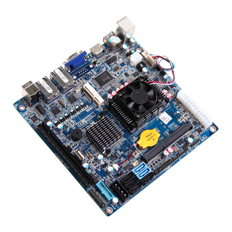
Port and Connectors:
1. JPF
Jumper JPF allows you to enable (force on) or disable
the Power Force On function. Ifenabled, the power will
always stay on automatically. If this function is disabled
(the normal setting), the user needs to press the power
button to power on the system.
Pin#
1-2 Disable
2-3 Enable
2. JL1
A Chassis Intrusion header is located at JL1 on the
motherboard. Attach the appropriate cable from the
chassis to inform you of a chassis intrusion when the
chassis is opened.
Pin#
1 Intrusion Input
2 GND
3. CLR_CMOS
Jumper CLR_CMOS is used to clear CMOS
4. USB prot
Intelnal USB2.0 port.
5. PCIE Slot
PCI-E x4 Gen2(in x16 physical)
6. F_USB2.0
Front Panel USB 2.0 header
Pin# Pin#
1 5V 2 5V
3 USB DO- 4 USB D1-
5 USB DO+ 6 USB D1+
7 GND 8 GND
9 N/A 10 NC
3
2
1
JPF
2
1
JL1
2
1
CLR_CMOS
12
10
F_USB2.0
7. F_USB3.0
Front Panel USB 3.0 header
Pin# Pin#
1 5V 2 F-USB3.0 RXDN2
3 F-USB3.0 RXDP2 4 GND
5 F-USB3.0 RXDN2 6 F-USB3.0 TXDP2
7 GND 8 F-USB2.0 0_N2
9 F-USB2.0 0_P2 10 F_OCP
11 F-USB2.0 0_P1 12 F-USB2.0 0_N1
13 GND 14 F-USB3.0 TXDP1
15 F-USB3.0 TXDN1 16 GND
17 F-USB3.0 TXDP1 18 F-USB3.0 TXDN1
19 5V 20 NC
8. TPM Header
This header is used to connect a Trusted Platform Module (TPM), available from a third-party
vendor. A TPM is a secu¬rity device that allows encryption and authentication of hard drives. It
enables the motherboard to deny access if the TPM associated with the hard drive is not installed
Pin# Pin#
1 CLK 2 GND
3 FRAME 4
5 RESET 6 5V
7 AD3 8 AD2
9 3V3 10 AD1
11 AD0 12 GND
13 RSV0 14 RSV1
15 3V3_SB 16 SERIRQ
17 GND 18 CLKRUN
19 LPCPD 20 RSV2
9. SATA
SATA 0,1are SATA3.0 headers,
SATA 2,3,4,5 are SATA2.0 headers.
Pin#
1 GND
2 TXP
3 TXN
4 GND
Pin#
5 RXN
6 RXP
7 GND
19
1
11
10
F_USB3.0
19
2
1
20
TPM
www.giadatech.com www.giadatech.com
3 4
