Giada MI-A75 User manual

www.giadatech.com User’s Manual
MI-A75
All right reserved
Version 001
Motherboard
(2) this device must accept any interference received, including interference that may cause undesired operation.
FCC ID:YIKMIR880G
This device complies with Part 15 of the FCC Rules. Operation is subject to the following two conditions:
(1) this device may not cause harmful interference, and

21
Gratitude ……………………………………………………………………………
I. About the product ………………………………………………………………
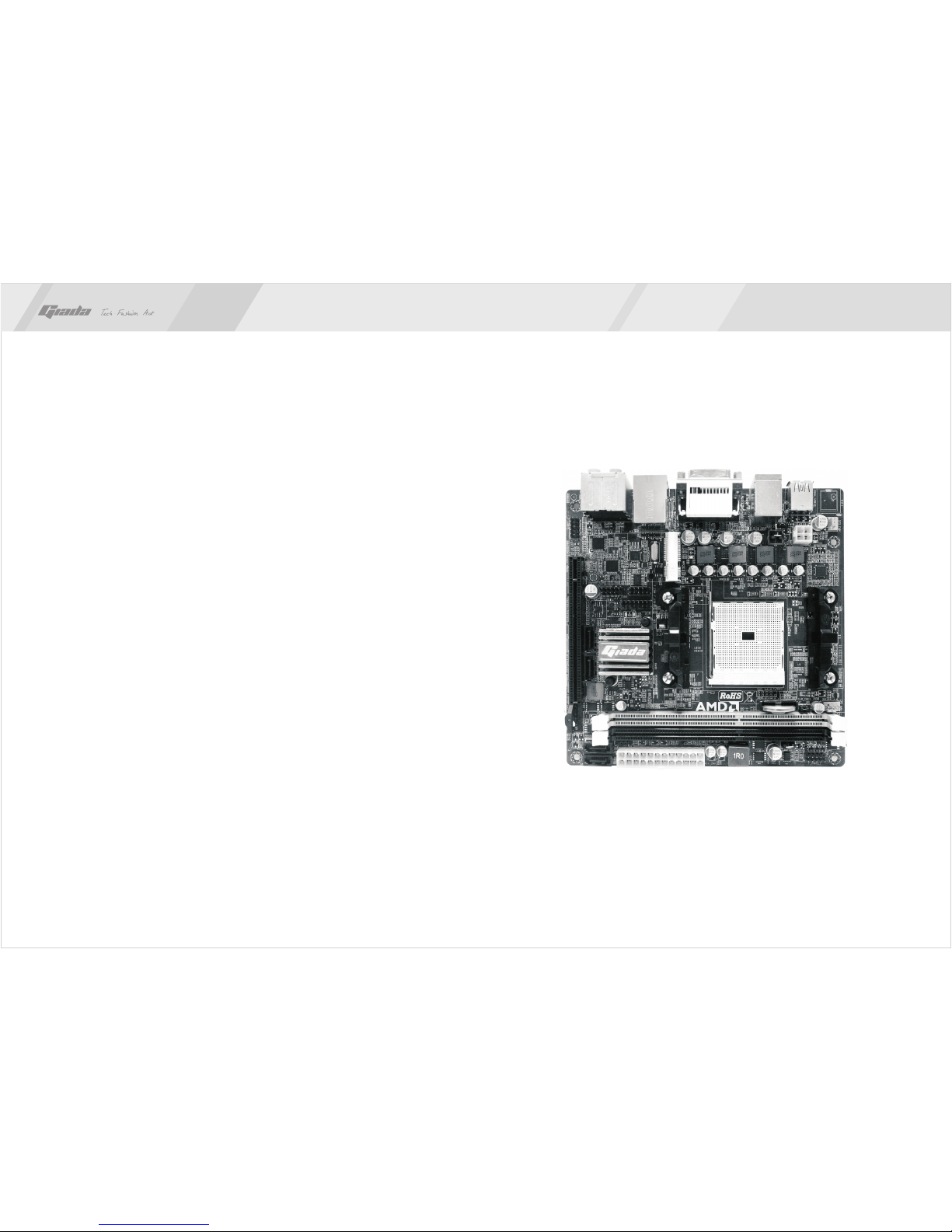
1. Picture of the motherboard ………………………………………………
2. Features ……………………………………………………………………
2.1 Processor ………………………………………………………………
2.2 Memory …………………………………………………………………
2.3 BIOS ……………………………………………………………………
2.4 Interfaces of peripherals ………………………………………………
2.5 Power management……………………………………………………
2.6 Expansion slot …………………………………………………………
II. Hardware installation……………………………………………………………
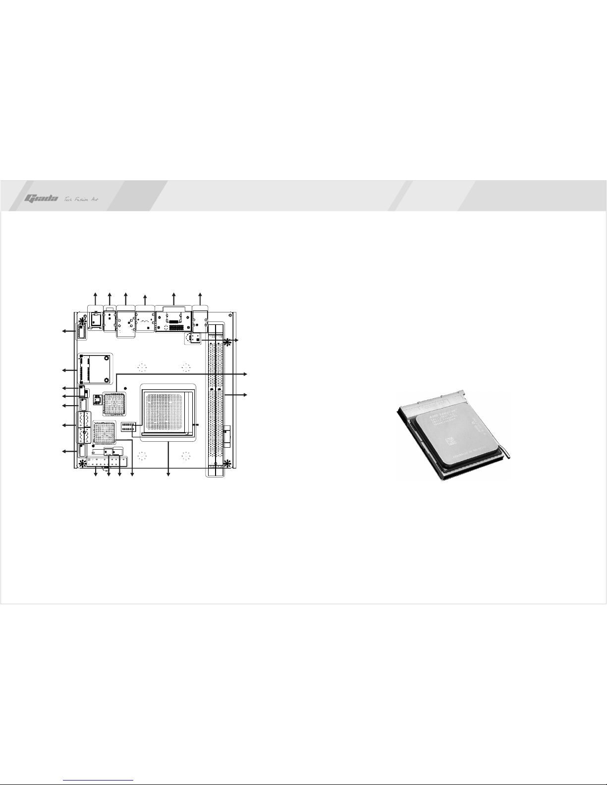
1. Layout of motherboard ……………………………………………………
2. Install CPU …………………………………………………………………
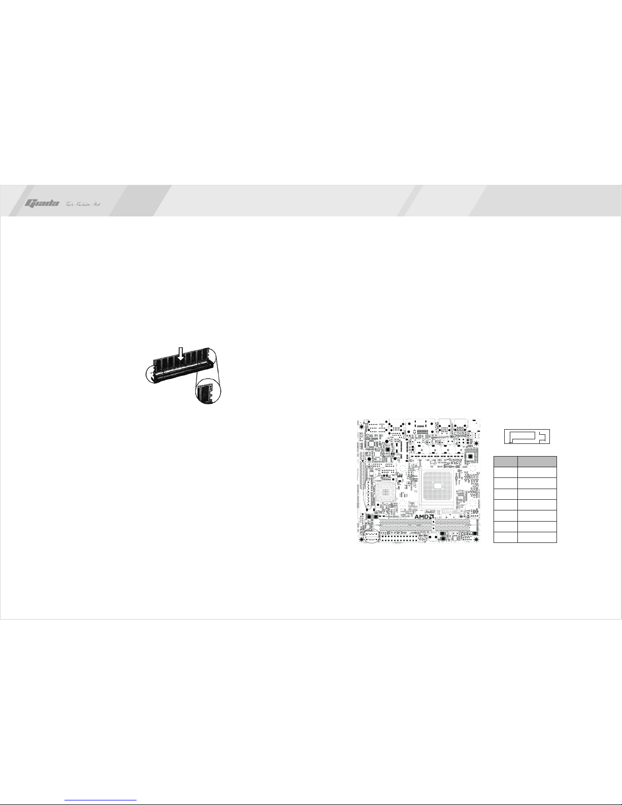
3. Installing memory …………………………………………………………
4. Install expansion slot card …………………………………………………
5. Motherboard jumper setting ………………………………………………
5.1 SATA1/SATA2/ SATA3/ SATA4 (Serial ATA flat-cable sockets)……
5.2 CPU_FAN/ SYS_FAN (CPU fan /System fan socket)………………
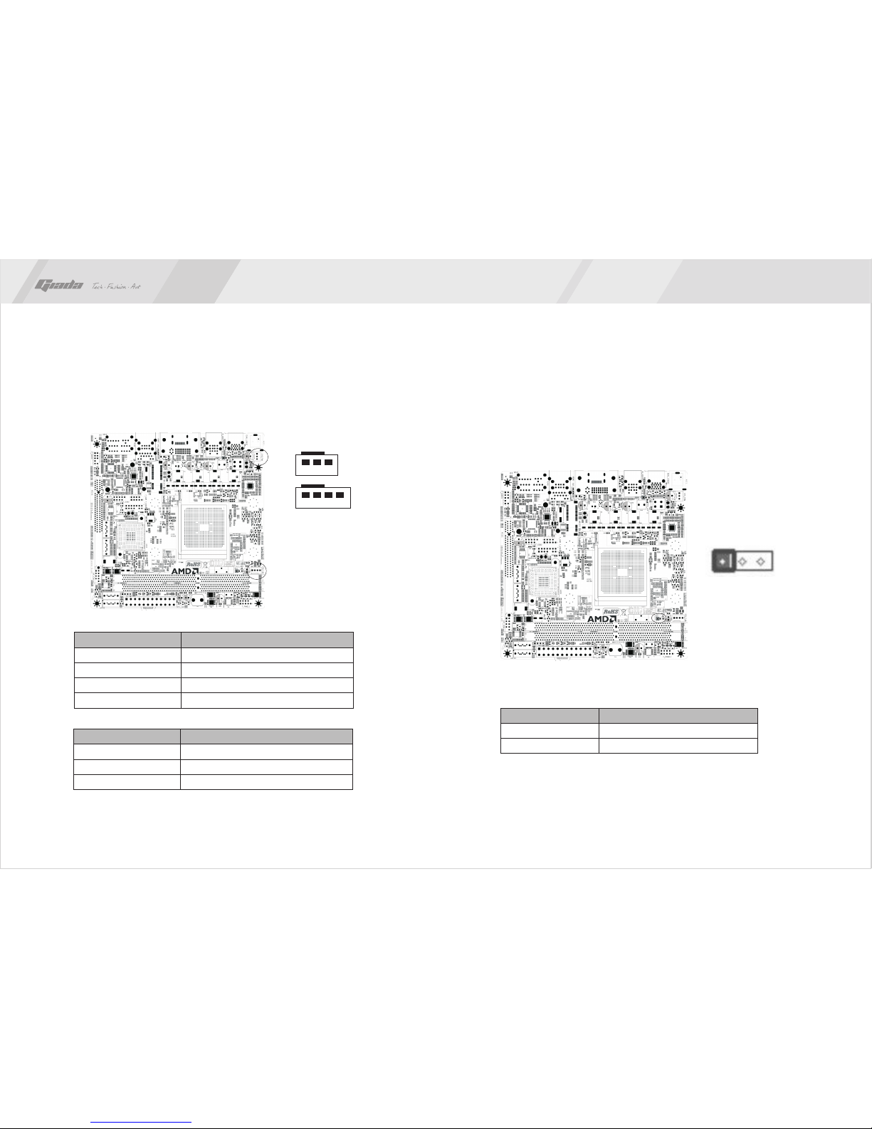
5.3 CLR_CMOS(CMOS pin) ………………………………………………
5.4 F_USB1 (frond-end USB pin) …………………………………………
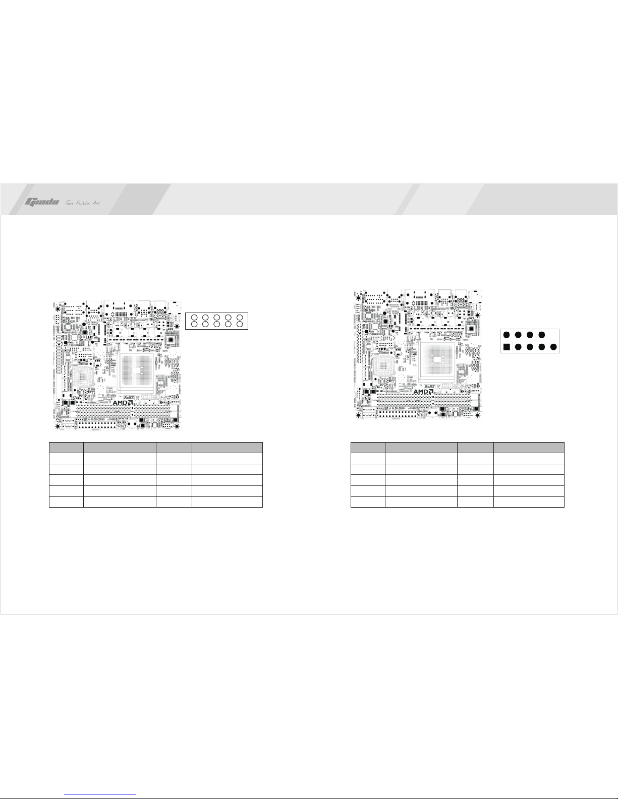
5.5 F_ AUDIO(Pins for front-end audio adapter) ………………………
5.6 ATX 20PIN(Power receptacle ) ………………………………………
5.7 ATX 12V (12V Power receptacle) ……………………………………
5.8 F_ PANEL (Front-end control panel) ………………………………
4. Rear panel interface ………………………………………………………
5.9 F_COM (Front end COM port) ………………………………………
Contents
III. BIOS setting ……………………………………………………………………
1. Main menu …………………………………………………………………
2. Main (standard CMOS setup) ……………………………………………
3. Advanced (Advanced BIOS setup) ……………………………………
3.1 CPU configuration ……………………………………………………
3.2 IDE Configuration ……………………………………………………
3.3 IO chipset configure …………………………………………………
3.4 PC health configuration ……………………………………………
4. Power ………………………………………………………………………
5. Boot …………………………………………………………………………
6. Security Setup ………………………………………………………………
7. Chipset ………………………………………………………………………
7.1 USB configuration ……………………………………………………
8. T.W.L …………………………………………………………………………
9. Exit …………………………………………………………………………
IV. Software installation ……………………………………………………………
1. Install driver for motherboard ……………………………………………
1.1 Install driver for chipset ………………………………………………
1.2 Install sound card driver ………………………………………………
1.3 Install driver for on-board LAN chip …………………………………
1.4 Install driver for graphic card …………………………………………
2. HD_AUDIO and sound card setup ………………………………………
V. Appendix …………………………………………………………………………
3
4
5
5
5
5
5
6
7
8
9
10
10
10
12
11
13
14
15
18
17
18
19
4
5
5
20
22
23
24
24
25
25
26
27
28
30
31
32
33
33
35
35
37
38
39
40
40
47
www.giadatech.com

4
3
Gratitude I. About the product
1. Picture of the motherboard
Thank you for choosing Giada motherboard.
®
Giada MI-A75 is based on AMD A75 chipset, support socket APU 905 type
processor.
It supports HT3.0 technology, DDR3 1333/1066 Dual-channel memory, 4*SATA3
port, 2*USB3.0, 8*USB2.0 port, on-board 7.1-channels HD-AUDIO sound card,
Supports S/PDIF out ports on rear,gigabit LAN and HDMI display output.
Any question about the product, please send e-mail to our support center.
Headquarter:
USA office: [email protected]
www.giadatech.com
NOTE: This is Giada real product photo show for your reference only, Product
appearance depends on goods.

6
5
2.1 Processor
· Support socket 905 APU type processor.
NOTE: This board only supports processor consumption less than or equal
to 65W.
· Support HT3.0.
2.2 Memory
·
·
2.3 BIOS
·
·
·
·
2.4 Interfaces for peripherals
·
·
·
·
·
·
·
·
·
2.5 Power management
·
·
2.6 Expansion slot
· 1* MINI-PCIe 1X slot at top side.
2. Features
Supports DDR3 1333/1066MHz memories * 2;
4GB at maximum; (2GB/per slot)
NO Supports PNP, APM and ATAPI;
Supports ACPI and DMI;
Automatic detection and supporting hard disk whose LBA mode is over 160G;
End-users can easily upgrade the motherboard with BIOS.
1* PS/2 Keyboard port
4* SATA3 HDD port (support 6Gb/s);
1* HDMI digital port;
1* DVI port;
8* high-speed transmission ports (max. 480Mb/s) which support USB2.0 and
are compatible with USB1.1;
1* RJ45 network interface (PCIe Gigabit Ethernet);
On-board HD-AUDIO audio adapter;
Interfaces on panels can be compatible with HDD LED, Speaker, etc;
1* CPU FAN socket.
Support APM and ACPI.
Compatible with energy star “Green PC”.
II. Hardware installation
www.giadatech.com
Warning
·
·
·
·
·
The motherboard consists of a great number of ICs and other components.
These ICs might be damaged by the static charge. Therefore, the user must
make the following preparations before installation:
Turn off the power of the computer. It is preferable the power cord be unplugged.
Take care not to contact the metal wires and theirs joints on the motherboard
when handling it.
It is preferable that the operator wear the anti-static wrist strap when handling
the IC components.
Before the ICs are installed, the components of the motherboard should be
placed on the anti-static mat or bag.
When you remove the plug on the ATX power supply of the motherboard, make
sure the switch of the power supply is in OFF state.
Installing the motherboard onto the computer case:
For most of the computer cases, the multiple fixing holes left on their bottoms can
be used for securing the motherboard and preventing short circuit. During your
operation, take care not to allow the screws to contact any circuit or part on PCB.
When circuits on the surface of the motherboard get close to the fixing holes, you
can use the plastic sheet to separate the screws from the board surface so as to
avoid damage or failure of the motherboard.

8
7
1. Layout of motherboard 2. Install CPU
Please install the APU in accordance with the following procedures:
· Locate the Socket 905 (APU) on motherboard.
· Pull the lever as shown below, beside the socket to 90 degree angle.
· Near the bottom of the socket (“Socket APU” printed) , there is one hole
missing at both left and right side. We use this feature as a direction marking
of APU installation. On the APU, there is also similar triangle mark on its edge
to identify the correct install direction.
· Alignment the processor socket marked with the central processor, put your
APU into the socket slowly, and pull the lever back.
NOTE: Be sure to install the APU follow the right Socket mark direction, otherwise
may cause damage to the central processor.
· After install the central processor, please mount APU fan on the central
processor and clip buckle in both sides of the socket.
· When the APU fan has been installed, please connect the fan power cord
into 4PIN “APU_FAN” socket on board.
www.giadatech.com
12
3
4
5
6
7
8
9
11
13
12
14 15 16 17 18
20
21
1. PS/2 Keyboard port + USB2.0 port
2. DVI + HDMI
3. USB2.0 port + e-SATA port
4. RJ45 NIC + USB2.0 port
5. 3jack audio
6. S/PDIF-out
7. Front audio
8. Mini PCIe slot
9. COM header
10. Clear CMOS
11. Front USB
12. SATA2.0 port
13. Front Panel
14. ATX PWR 20PIN
15. SYS FAN
16. CPU FAN
17. South Bridge
18. CPU socket
19. Memory slot
20. North Bridge
21. ATX PWR 4PIN
10 19
NOTE: This motherboard does not support dual display DVI and HDMI.
VGA display via DVI to VGA adapter can not get the Maximum resolution.
This motherboard does not support some AOC monitor.

10
9
www.giadatech.com
3. Installing memory
Please install the memory in accordance with the following procedures:
· Remove the buckle at the two ends of the interface slot for the memory;
· Align the golden finger of the memory to the groove of the interface slot and
pay attention the concave hole of golden finger should be aligned to the
convex point of the slot.
· Finally, insert the memory into the interface slot gently. If no error occurs at the
moment, insert the card forward in the slot till the white buckle is automatically
engaged in the concave hole at the two sides of the memory.
Note
In order to avoid damages to the motherboard or the components, the user must
make sure the power supply to the computer is turned off before the memory or
other component is installed or removed. As the groove is set at the golden finger
of the DDR DIMM, the memory can only be inserted into the slot with one direction.
During installation, the user only needs to align the golden finger and the
dual-channel groove of the interface slot and insert it gently. To avoid damage,
never apply excessive force in that process.
switch out the white buckle on
both ends of the DIMM
4. Install expansion slot card
Installing Mini-PCIE extended devices
At the top side of motherboard there is a Mini-PCIE extended slots, which user
can connected WIFI module and Bluetooth module etc.
5. Motherboard jumper setting
Note:The user should notice that all sockets are marked with PIN1. The mark “#”
indicates the default values.
5.1. SATA1/SATA2/ SATA3/ SATA4 (Serial ATA flat-cable sockets)
Serial ATA sockets can reach a transmission speed of 300MB/s, and you can
connect your Serial ATA device to this socket.
71
PIN Definition
1
2
3
4
5
6
7
GND
TXP
TXN
GND
RXN
RXP
GND

12
11
5.2. CPU_FAN/ SYS_FAN (CPU fan /System fan socket)
This receptacle can be used for connecting CPU/system fan. Its pins are
defined below. The user shall make sure the fan is conforming.
CPU PIN Definition
1
2
3
4
GND
12V
SIGNAL
CTRL
SYS PIN Definition
1
2
3
VSS
VDD
TAC
123
1 2 3 4
PIN Definition
1-2#
2-3
Normal
CLR_CMOS
www.giadatech.com
1 2 3
5.3. CLR_CMOS(CMOS pin)
The correct time, system hardware and other information are saved in the
CMOS memory of the motherboard. The interruption the computer's power
won't cause the loss of this information, for the CMOS is powered by the
battery on the motherboard. The port is defined as follows:

14
13
www.giadatech.com
5.4. F_USB1 (frond-end USB pin)
In case the USB ports on the rear panel of the machine case are not enough,
the user can use the extension USB pins provided by this motherboard.
These ports support USB 2.0 devices. The definitions of the ports are
described below:
PIN
1
3
5
7
9
Definition
5V
USB D0-
USB D0+
GND
NULL
PIN
2
4
6
8
10
10
Definition
5V
USB D1-
USB D1+
GND
NULL
1
2
5.5. F_ AUDIO(Pins for front-end audio adapter)
These audio adapter ports allow you to connect to the wire harness of the
audio adapter. After connection, you can easily control the audio
output/microphone through the front panel of the host (Note: Don't connect
the wire to Pin 4).
The definitions of the ports are described below:
10
1
2
Definition
GND
5V
-
NULL
-
PIN
2
4
6
8
10
Definition
MIC
MIC-BIAS
OUT-R
GND
OUT-L
PIN
1
3
5
7
9
9

16
15
5.7. ATX 12V (12V Power receptacle)
Besides standard 20-pin PWRATX1 power receptacle, this board has a
special 12V power receptacle for CPU. For better and more stable processor
power supply, we suggest keeping the connection on this socket. The
definitions of the pins are described below (when power supply with 20-pin
outlet is used, please make sure the numbers are matched correctly):
www.giadatech.com
1
PIN Definition
1
2
3
4
GND
GND
12V
12V
5.6 ATX 20PIN(Power receptacle )
This socket is for 24PIN standard ATX power. The definitions of the ports are
described below:
Definition
3.3V
5V
5V
PG
12V
3.3V
-12V
PS-ON
GND
-5V
5V
GND
PIN
2
4
6
8
10
12
14
16
18
20
22
24
Definition
3.3V
GND
GND
GND
5VSB
12V
3.3V
GND
GND
GND
5V
5V
PIN
1
3
5
7
9
11
13
15
17
19
21
23

18
17
www.giadatech.com
Definition Definition
PLED+(VCC)
GND
NULL
PWBT
GND
RXD1
DTR1
DSR1
CTS1
NC
PIN PIN
2
4
6
8
10
2
4
6
8
10
Definition Definition
HDLED+
GND
RST+
RST+
NULL
DCD1
TXD1
GND
RTS1
RI1
PIN PIN
1
3
5
7
9
1
3
5
7
9
5.8. F_ PANEL (Front-end control panel)
This socket is used to connect the flat cables on the front-end panel.
NOTE: HDLED+/HDLED- for HDD indicator; PLED+/PLED- for power indicator;
PW+/PW- for power button; RST+/RST for reset button
5.9. F_COM (Front end COM port)
2
1
4
3
6
5
8
7
10
9

20
19
4. Rear panel interface
1. Antenna aperture
2. USB2.0 port
3. PS/2 KB + USB2.0 port
4. DVI port (top)
5. HDMI port (bottom)
6. RJ45 port + USB3.0 port
7. 6jack (including 1*optical S/PDIF-out)
NOTE: This motherboard does not support dual display DVI and HDMI.
VGA display via DVI to VGA adapter can not get the Maximum resolution.
This motherboard does not support some AOC monitor.
Note
The descriptions relating to BIOS in this Manual can only be used for reference
as the BIOS version of the motherboard is upgraded continuously. Giada provides
no guarantee that the contents in this Manual be consistent with the information
you acquire.
BIOS is a basic I/O control program saved in the Flash Memory. Bridging the
motherboard and the operating system, BIOS is used for managing the setup of
the related parameters between them. When the computer is activated, the
system is first controlled by the BIOS program. First, a self-detection called POST
is performed to check all hard devices and confirm the parameters of the
synchronous hardware. Once all detections are completed, BIOS will hand over
the controlling to the operating system (OS). As BIOS serves as the only channel
that connects the hardware and software, whether your computer can run stably
and work in optimized state will hinge on how to properly set the parameters in
BIOS. Therefore, the correct setup of BIOS plays a key role in stably running the
system and optimizing its performance.
The CMOS Setup will save the set parameters in the built-in CMOS SRAM on the
motherboard. When the power is shut off, the lithium battery on the motherboard
will provide continuously power for CMOS SRAM. The BIOS setup program will
allow you to configure the following items:
1.HD drive, floppy drive and peripheral devices;
2.Video display type and display items;
3.Password protection;
4.Power management characteristics.
A.State of BIOS Setup
When the computer is started up, BIOS will run the self-detection (Post) program.
This program includes series of diagnosis fixed in BIOS. When this program is
executed, the following information will appear if any error is found:
Press F1 to Run Setup
Press F2 to Load default values and continue
12 3 46 7
III. BIOS Setting
5
www.giadatech.com

22
21
Key
↑ (Up key)
↓ (Down key)
← (Left key)
→ (Right key)
ESC
Page Up
Page Down
F1
F7
F8
F9
F10
Function
Move to the previous item
Move to the next item
Move to the left item
Move to the right item
Exit the current interface
Change the setup state, or add the values
Change the setup state, or deduct the values
Display the information of the current setup
Load the set values of previous time
Load the safest values
Load the optimized values
Save the settings and exit the CMOS SETUP
C.Auxiliary information
Main interface
When the system enters the main interface of Setup, the major selected contents
will be displayed at the lower part of the interface with the change of the options.
Set interface
When you set the value for each column, you can view the preset value of the
column and the values that can be set if you press F1, for example, the BIOS
default values or CMOS Setup values. To exit the interface for auxiliary
information, press [ESC].
To enter BIOS, you can press F1; to load the default values and enter the system,
you can press F2. After the self-detection process is completed, you can press
DEL to enter the BIOS interface if no error is found. If the indicative information
disappears before you can act, you can shut off the computer and turn on it again,
or you can press the key RESET on the machine case. To restart your computer,
you can also simultaneously press <Ctrl>+<Alt>+<Delete>.
B. Function Keys definitions
1. Main menu
When the system enters the CMOS Setup menu, you can see the main menu on
the upper part of the screen, as shown in Figure 3.1. In this main menu, you can
use the left and right direction keys to select the setup items. Once the item is
selected, the lower part of the computer screen will show the details of setting.
(The options above and their contents may be different from your actual options,
so they are used for reference only).
· Main (standard CMOS setup)
This item is used for setting the date, time, specifications of hard disk and
floppy disk and type of monitor.
· Advanced (advanced BIOS setup)
This item is used for setting the advanced functions provided by BIOS, such
as the virus alarm and priority order of disks for startup process.
· Power(ACPI) power management
This item includes ACPI advance configuration and power management
Fig 3.1
www.giadatech.com

2423
· Boot (startup configuration characteristics)
· Security (setting the administrator/user password)
· Chipset (chipset performance setting)
· T.W.L (K10 black box CPU OC module)
Provide OC option for CPU FSB.
· Exit (option of exit)
This item includes load optimal defaults/load failsafe defaults value/discard
changes/ discard changes and exit.
2. Main (standard CMOS setup)
· System time (hh:mm:ss)
Use this item to set the time for the computer, with the format as
“hour/minute/second”.
· System date (mm:dd:yy)
Use this item to set the date for the computer, with the format as “week,
month/day/year”.
Fig 3.2
3. Advanced (Advanced BIOS setup)
3.1 CPU configuration
· K10 CPU overclocking configuration
For K10 core frequency doubling adjustable CPU configuration.
Item: [Disable][Enable]
· Processor Voltage[Auto]
· Secure Virtual Machine Mode
[Enable] or [Disable] microcode update function.
· Cool&Quiet
Cool & Quiet technology is an innovative solution used for AMD processor-
based systems. It can reduce operating power consumption and system noise,
while delivering performance on demand. Supports peak computing
experience. AMD and its partners to make CnQ technology as system
characteristics, which consists of the following components: support CnQ a
processor, motherboard, supporting BIOS, software driver and CPU cooler.
Fig 3.3
www.giadatech.com

2625
3.2 IDE Configuration
· Hard Disk Write Protect
This item uses for enable or disable write-protection function. This function only
works while access devices through BIOS.
· IDE Detect time out (Sec)
This item uses for choose ATA/ATAPI devices auto-detection time.
Could be set as:[0][5][10][15][20][25][30][35].
3.3 IO chipset configure
· OnBoard Floppy Controller
Default:[Enable]
· Floppy Drive Swap
Swap two floppy drivers' volume label.
· Serial Port2 Address
Set build-in serial port1's (COM 1) address. Options are:[Disable],[3F8/IRQ4],
[2F8/IRQ3],[3E8/IRQ4],[2E8/IRQ3],[Auto].
Default:[3F8/IRQ4]
· Serial Port2 Mode
[Normal] mode for mouse and modem application.
If IrDA function is used, then [IrDA ASKIR] mode is recommended.
3.4 PC health configuration
· H/W Health Function
This setting can open system hardware status display, CPU fan and CPU
temperature can be observed in the COMS. Some new models have added
the CPU overheat alarm and auto power-off function in COMS to protect
hardware, usually set to 80 degrees.
· CPU Fan Speed Control
CPU FAN modes:[Manual Mode],[Full On Mode],[Thermal Cruise Mode]
Fig 3.5
www.giadatech.com
Fig 3.4
Fig 3.6

28
27
5. Boot
·
If this item is set as Enabled, the system can be started within five seconds and
some detection items will be ignored. The options are [Disabled] and [Enabled].
· Quiet Boot
To start the system quietly. (Full Screen Log display can be shut down).
· Add On ROM Display Mode [Force BIOS]
This item allows you to set the display mode of the device's firmware program.
The options are [Force BIOS] and [Keep Current].
· Bootup Num-Lock
(To set the state of Num Lock after start-up). Options are OFF and ON. In other
words, this item can be used for setting the state of Num Lock for the time the
system has been started. It can be set on the basis of the needs of the user and
doesn't affect the performance of the computer.
· PS2 Mouse Support
Set to support PS2 mouse. The available options are [Auto] and [Disable]. The
default value is Auto.
Quick Boot
Fig 3.8
www.giadatech.com
4. Power
Fig 3.7
·
Set power mode that the system supports.
· ACPI APIC support
You can add ACPI APIC table to RSDT direction list by this item.
· Restore on AC Power Loss
This option can set the computer back to the state when AC power loss.
"Power Off" to keep the system turned off, "Power On" to start-up the system
automatically, "Last State", is maintained to the state before the power failure.
· Wake-Up by PCI Card
· Wake-Up by PCIE
· RTC Resume
You can use clock to start-up system if this item sets as [Enable]
ACPI Version Features

30
29
6. Security Setup
· Wait For“F1” If any Error
(The system waits the user to press F1 if any error occurs from the computer).
The options are Disable and Enable. Normally, it is set as Enable. Then if the
computer has any error, a line of English words will appear on the screen,
reminding the user of pressing F1 to enter CMOS for setup. If it is set as
Disable, that line of English words won't appear. However, if the words “wait…”
appear during the start up process and you press Del, the system can also
enter CMOS for setup.
· Hit “Del” Message Display
(Information is displayed when the computer is started, suggesting the user
can press “Del” to enter the state for CMOS setup). The options are [Disable]
and [Enable]. Normally, [Enable] is selected. After [Enable] is selected, the
information on how to enter the state for CMOS setup will be displayed at the
time the computer is started. If [Disable] is selected, such information won't be
displayed. However, if you press “Del” when the character “Wait……” appears
at the time the computer is started, the system can also enter the state for
CMOS setup.
· nterrupt 19 Capture [Disabled]
If you use some PCI extension cards with built-in firmware program (like SCSI
extension card) and you want to start the system through Interrupt 19, you can
set this item as [Enabled]. The options are [Disabled] and [Enabled].
· Boot Device Priority
To set the booting priority.
· Hard Disk Drives
To set the booting priority of hard disk devices.
· Removable Drives
To set the booting priority of removable devices.
· CD/DVD Drives
To set the booting priority of CD/DVD-ROM devices.
Fig 3.9
www.giadatech.com
If this function is selected, the following information will appear:
Enter New Password hhhhhh
Then, enter the password with not more than eight characters and press <Enter>.
BIOS will requires to enter the password again. Once you enter it again, BIOS will
save the set password.
Once the password item is enabled, you will be required to enter the password
each time before the system goes to the set program of BIOS. The user can set
this item through the Security Option in advanced BIOS properties. If the item
Security Option is set as System, the password will be required to be entered
before the system guides and goes to the set program of BIOS. If set as Setup,
the password will be required to be entered only before the system goes to the
set program of BIOS.
To delete the password, press <Enter> in the popped-up window that requires to
enter the password. Then, information for confirmation will appear on the screen
to allow you decide whether the password is disabled. Once the password is
disabled, you won't have to enter the password and can enter the setup program
directly when the system is restarted.

32
31
Boot Sector Virus Protection
This item is used for setting the alarm function in the case of virus attack in IDE
disk sector. If this item is set as Enable and some program wants to write information
in the sector, BIOS will display alarm information on the screen and buzz.
7. Chipset
· NorthBridge Configuration
· SouthBridge Configuration
www.giadatech.com
Fig 3.10
7.1 USB configuration
· Legacy USB Support
This item is used to enable or disable USB device support function. When set
to the default value [Auto], the system can be automatically detected whether
USB devices exist when system is booting up, and if so, start the USB
controller; otherwise it will not start. But if you set [Disabled], then whether or
not the USB device exists, USB controller within the system is turned off.
Configuration options: [Disabled] [Enabled] [Auto].
· USB2.0 Controller Mode
This item is used to set the USB 2.0 devices Transfer rate mode. Settings were
HiSpeed (480 Mbps) and Full Speed (12 Mbps) mode. Configuration options:
[HiSpeed] [FullSpeed].
Fig 3.11

34
33
· Exit Options
The exit options include load optimal defaults/load failsafe defaults
value/discard changes/discard changes and exit.
· Load failsafe defaults /optimal defaults
These two items can allow the user to restore all BIOS options to the failsafe
defaults and optimal defaults. The optimal defaults are set to optimize the
performance of the motherboard. The failsafe defaults are conservative values
for the system.
If you enter OK and press Enter, all set values will be saved to CMOS SRAM
and the system will exit from the BIOS setup program. If you don't want to save,
you can press Cancel or Esc to return to the main menu.
· Discard Changes and Exit
If you enter OK and press Enter, the system will exit from the BIOS setup
program. If press Cancel or ESC, return to the main menu.
· Discard Changes
If you enter OK and press Enter, the system will discard the changes. If press
Cancel or Esc, return to the main menu.
8. T.W.L
This item can adjust the CPU FSB.
Note: adjust the CPU FSB can cause the system not booting, need to manually
clear the CMOS.
9. Exit
Fig 3.12
www.giadatech.com
Fig 3.13

36
35
NOTE:Pictures below just showing the driver install steps, please see the real
product for detailed information.
1. Install driver for motherboard
After you complete the installation of the operating system, you should then
install the driver for the motherboard. To this end, put the disk into the CD-ROM.
The interface as shown in Fig. 4.1 will appear.
In Fig 4.1, click "Driver ", another UI appears as shown in Fig 4.2.
IV. Software installation
Fig. 4.1
Fig. 4.2
www.giadatech.com

3837
Fig. 4.3
Fig. 4.4
Fig. 4.2, a dialog box as shown in Fig. 4.4 will pop up. Then you can click
“Next” and wait till the driver is installed completely.
1.2 Install Sound card driver
After you click “Install” behind the “Realtek HD audio driver” in the interface of
1.1. Installing driver for Chipset
After you click “Install” behind the “Chipset driver” in the interface of Fig. 4.2,
a dialog box as shown in Fig. 4.3 will pop up. Then you can click Next and
wait till the driver is installed completely.
www.giadatech.com
This manual suits for next models
1
Table of contents
Other Giada Motherboard manuals

Giada
Giada ION2 User manual

Giada
Giada MI-E350T User manual

Giada
Giada N70E-DR ITX NAS User manual

Giada
Giada MI-H67 User manual

Giada
Giada AP23 User manual

Giada
Giada N30M-VA User manual

Giada
Giada MI-D525 User manual

Giada
Giada NI-A20 User manual

Giada
Giada NI-R3188 User manual

Giada
Giada N21M-MV User manual