Atop EH9711 Series User manual

Industrial Managed
Ethernet Switch –EH9711
User Manual
Page 1of 223
Industrial Managed
Ethernet Switch
User Manual
V0.4
October 21th, 2022
This PDF Document contains internal hyperlinks for ease of navigation.
For example, click on any item listed in the Table of Contents to go to that page.
Series covered by this manual:
EH9711
Atop Technologies, Inc.

Industrial Managed
Ethernet Switch –EH9711
User Manual
Page 3of 223
Important Announcement
The information contained in this document is the property of Atop Technologies, Inc., and is supplied for the sole purpose
of operation and maintenance of Atop Technologies, Inc., products.
No part of this publication is to be used for any other purposes, and it is not to be reproduced, copied, disclosed, transmitted,
stored in a retrieval system, or translated into any human or computer language, in any form, by any means, in whole or in
part, without the prior explicit written consent of Atop Technologies, Inc.,
Offenders will be held liable for damages and prosecution.
All rights, including rights created by patent grant or registration of a utility model or design, are reserved.
Disclaimer
We have checked the contents of this manual for agreement with the hardware and the software described. Since deviations
cannot be precluded entirely, we cannot guarantee full agreement. However, the data in this manual is reviewed regularly and
any necessary corrections will be included in subsequent editions.
Suggestions for improvement are welcome. All other product’s names referenced herein are registered trademarks of their
respective companies.
Preface
This manual contains some advanced network management knowledge, instructions, examples, guidelines, and general
theories. The contents are designed to help users manage the switch and use its software, a background in general theory is a
must, when reading it. Please refer to the Glossary for technical terms and abbreviations.
Who Should Use This User Manual
This manual is to be used by qualified network personnel or support technicians who are familiar with network operations,
and might be useful for system programmers or network planners as well. This manual also provides helpful and handy
information for first time users. For any related problems, please contact your local distributor. If they are unable to assist
you, please redirect your inquiries to www.atoponline.com .
Warranty Period
Atop technology provides a limited 5-year warranty for managed Ethernet switches.
Documentation Control
Author:
Saowanee Saewong
Revision:
0.4
Revision History:
Initial
Creation Date:
14 July 2022
Last Revision Date:
21 October 2022
Product Reference:
Layer-2 Managed Switch –EH9711
Document Status:
Released

Industrial Managed
Ethernet Switch –EH9711
User Manual
Page 4of 223
Table of Contents
1Introduction.......................................................................................................................13
1.1 Introduction to Industrial Managed Switch..............................................................................................13
1.2 Software Features..................................................................................................................................14
1.3 Introduction to the Document.................................................................................................................14
2Configuring with a Web Browser.........................................................................................15
2.1 System ...................................................................................................................................................17
2.1.1 Information .............................................................................................................................................17
2.1.2 IP............................................................................................................................................................18
2.1.3 NTP ........................................................................................................................................................21
2.1.4 Time........................................................................................................................................................22
2.1.5 Log..........................................................................................................................................................24
2.1.6 DIP Switch..............................................................................................................................................25
2.1.7 Alert........................................................................................................................................................26
2.1.8 SMTP Setting .........................................................................................................................................26
2.2 Ports.......................................................................................................................................................28
2.3 ERPS......................................................................................................................................................30
2.4 DHCPv4 .................................................................................................................................................34
2.4.1 Snooping ................................................................................................................................................34
2.4.2 Relay ......................................................................................................................................................35
2.5 Security ..................................................................................................................................................37
2.5.1 Switch.....................................................................................................................................................37
2.5.2 Network ..................................................................................................................................................56
2.5.3 AAA ........................................................................................................................................................82
2.6 Aggregation............................................................................................................................................85
2.6.1 Common.................................................................................................................................................86
2.6.2 Groups....................................................................................................................................................86
2.6.3 LACP......................................................................................................................................................87
2.7 Spanning Tree........................................................................................................................................88
2.7.1 Bridge Settings.......................................................................................................................................89
2.7.2 MSTI Mapping........................................................................................................................................90
2.7.3 MSTI Priorities........................................................................................................................................92
2.7.4 CIST Ports..............................................................................................................................................92
2.7.5 MSTI Ports .............................................................................................................................................95
2.8 IPMC.......................................................................................................................................................96
2.8.1 IGMP Snooping......................................................................................................................................96
2.8.2 MLD Snooping........................................................................................................................................99
2.9 LLDP.....................................................................................................................................................101
2.9.1 LLDP.....................................................................................................................................................102
2.10 SyncE...................................................................................................................................................103
2.11 MAC Table ...........................................................................................................................................107
2.12 VLANs ..................................................................................................................................................108
2.12.1Configuration........................................................................................................................................109
2.12.2SVL.......................................................................................................................................................112
2.13 VCL.......................................................................................................................................................114
2.13.1MAC-based VLAN................................................................................................................................114
2.13.2Protocol-based VLAN...........................................................................................................................114
2.13.3IP Subnet-based VLAN........................................................................................................................116
2.14 QoS ......................................................................................................................................................117
2.14.1Port Classification.................................................................................................................................117
2.14.2Port Policing .........................................................................................................................................119
2.14.3Queue Policing.....................................................................................................................................120
2.14.4Port Scheduler......................................................................................................................................121
2.14.5Port Shaping.........................................................................................................................................123

Industrial Managed
Ethernet Switch –EH9711
User Manual
Page 5of 223
2.14.6Port Tag Remarking.............................................................................................................................125
2.14.7Port DSCP............................................................................................................................................126
2.14.8DSCP-Based QoS................................................................................................................................127
2.14.9DSCP Translation.................................................................................................................................129
2.14.10 DSCP Classification.....................................................................................................................130
2.14.11 QoS Control List...........................................................................................................................130
2.14.12 Storm Policing..............................................................................................................................134
2.15 Mirroring ...............................................................................................................................................134
2.16 PTP.......................................................................................................................................................137
2.17 GVRP ...................................................................................................................................................139
2.17.1Global config ........................................................................................................................................140
2.17.2Port config ............................................................................................................................................141
2.18 DDMI ....................................................................................................................................................141
2.19 UDLD....................................................................................................................................................142
2.20 SD Backup ...........................................................................................................................................144
2.21 Modbus Setting ....................................................................................................................................145
2.22 Modbus Memory Map...........................................................................................................................153
3Monitor...........................................................................................................................159
3.1 System .................................................................................................................................................159
3.1.1 Information ...........................................................................................................................................159
3.1.2 CPU Load.............................................................................................................................................160
3.1.3 IP Status...............................................................................................................................................160
3.1.4 IPv4 Routing Info. Base .......................................................................................................................161
3.1.5 IPv6 Routing Info. Base .......................................................................................................................162
3.1.6 Log........................................................................................................................................................163
3.1.7 Detailed Log .........................................................................................................................................164
3.1.8 Power Status........................................................................................................................................165
3.1.9 Digital Input ..........................................................................................................................................165
3.2 Ports.....................................................................................................................................................165
3.2.1 State.....................................................................................................................................................165
3.2.2 Traffic Overview ...................................................................................................................................166
3.2.3 QoS Statistics.......................................................................................................................................167
3.2.4 QCL Status...........................................................................................................................................167
3.2.5 Detailed Statistics.................................................................................................................................168
3.2.6 Name Map............................................................................................................................................169
3.3 ERPS....................................................................................................................................................170
3.4 DHCPv4 ...............................................................................................................................................172
3.4.1 Snooping Table ....................................................................................................................................172
3.4.2 Relay Statistics.....................................................................................................................................172
3.4.3 Detailed Statistics.................................................................................................................................173
3.5 Security ................................................................................................................................................174
3.5.1 Network ................................................................................................................................................174
3.5.2 AAA ......................................................................................................................................................181
3.5.3 Switch...................................................................................................................................................185
3.6 Aggregation..........................................................................................................................................189
3.6.1 Status ...................................................................................................................................................189
3.6.2 LACP....................................................................................................................................................190
3.7 Spanning Tree......................................................................................................................................192
3.7.1 Bridge Status........................................................................................................................................192
3.7.2 Port Status............................................................................................................................................193
3.7.3 Port Statistics .......................................................................................................................................193
3.8 IPMC.....................................................................................................................................................194
3.8.1 IGMP Snooping....................................................................................................................................194
3.8.2 MLD Snooping......................................................................................................................................197
3.9 LLDP.....................................................................................................................................................199
3.9.1 Neighbors.............................................................................................................................................199
3.9.2 Port Statistics .......................................................................................................................................200
3.10 PTP.......................................................................................................................................................201

Industrial Managed
Ethernet Switch –EH9711
User Manual
Page 6of 223
3.10.1PTP.......................................................................................................................................................201
3.10.2802.1AS Statistics................................................................................................................................202
3.11 MAC Table ...........................................................................................................................................203
3.12 VLANs ..................................................................................................................................................203
3.12.1Membership..........................................................................................................................................203
3.12.2Ports.....................................................................................................................................................204
3.13 DDMI ....................................................................................................................................................206
3.13.1Overview ..............................................................................................................................................206
3.13.2Detailed ................................................................................................................................................206
3.14 UDLD....................................................................................................................................................207
4Diagnostics .....................................................................................................................209
4.1 Ping (IPv4)............................................................................................................................................209
4.2 Ping (IPv6)............................................................................................................................................211
4.3 Traceroute (IPv4) .................................................................................................................................212
4.4 Traceroute (IPv6) .................................................................................................................................214
5Maintenance....................................................................................................................216
5.1 Restart Device......................................................................................................................................216
5.2 Factory Defaults...................................................................................................................................217
5.3 Software ...............................................................................................................................................218
5.3.1 Upload..................................................................................................................................................218
5.3.2 Image Select ........................................................................................................................................218
5.4 Configuration........................................................................................................................................219
5.4.1 Save startup-config ..............................................................................................................................219
5.4.2 Download .............................................................................................................................................220
5.4.3 Upload..................................................................................................................................................220
5.4.4 Activate.................................................................................................................................................221
5.4.5 Delete...................................................................................................................................................222
6Diagnostics .....................................................................................................................223
Table of Figures
Figure 2.1 IP Address for Web-based Setting..........................................................................................................15
Figure 2.2 Login page ..............................................................................................................................................16
Figure 2.3 Webpage after a successful login...........................................................................................................16
Figure 2.4 Submenus under ConfigurationSystem Menu ....................................................................................17
Figure 2.5 System Information Configuration Webpage..........................................................................................17
Figure 2.6 Webpage to Configure System’s IP Information.....................................................................................18
Figure 2.7 Webpage to Configure System’s IP Configuration .................................................................................19
Figure 2.8 Webpage to Configure System’s IP Interfaces .......................................................................................19
Figure 2.9 Webpage to Configure System’s IP Routes ...........................................................................................21
Figure 2.10 Webpage to Configure System NTP.....................................................................................................22
Figure 2.11 Webpage to Configure System Time....................................................................................................23
Figure 2.12 Webpage to Configure System Log......................................................................................................25
Figure 2.13 Webpage to Configure System DIP Switch ..........................................................................................26
Figure 2.14 Webpage to Configure System Alert ....................................................................................................26
Figure 2.15 Webpage to Configure System SMTP Setting......................................................................................27
Figure 2.16 Example of SMTP Setting.....................................................................................................................27
Figure 2.17 Webpage to Configure Ports.................................................................................................................29
Figure 2.18 An Example of Ring Topology (a) Major Ring, and (b) Sub-Ring (Example made on EH7520) ..........31
Figure 2.19 Webpage to Configure ERPS .....................................................................................................................32
Figure 2.20 After Clicking to Configure ERPS.........................................................................................................33
Figure 2.21 Submenus under the DHCP Main Configuration Menu.................................................................................34
Figure 2.22 Webpage to Configure DHCPv4 Snooping..................................................................................................35
Figure 2.23 Webpage to Configure DHCPv4 Relay .......................................................................................................36

Industrial Managed
Ethernet Switch –EH9711
User Manual
Page 7of 223
Figure 2.24 Configuration-> Security Menu..................................................................................................................37
Figure 2.25 Configuration-> Security -> Switch Menu...................................................................................................38
Figure 2.26 Webpage to Configure Security Switch Users..............................................................................................38
Figure 2.27 Webpage to Configure Security Switch Users –After Clicked Add New User Button ....................................39
Figure 2.28 Webpage to Edit User...........................................................................................................................39
Figure 2.29 Webpage to Configure Privilege Levels of the Switch ..................................................................................41
Figure 2.30 Webpage to Configure Switch Authentication Method .................................................................................42
Figure 2.31 Webpage to Configure SSH .......................................................................................................................43
Figure 2.32 Webpage to HTTPS Configuration .......................................................................................................44
Figure 2.33 Webpage to HTTPS Configuration with Certificate Uploading .............................................................44
Figure 2.34 Webpage to Configure SNMP System.........................................................................................................45
Figure 2.35 Webpage to Configure SNMP Trap Destinations .........................................................................................46
Figure 2.36 Adding New Entry to SNMP Trap Destination Table............................................................................46
Figure 2.37 Webpage to Configure SNMP Trap Sources ................................................................................................47
Figure 2.38 Adding New Entry to SNMP Trap Sources...........................................................................................47
Figure 2.39 Webpage to Configure SNMP Communities................................................................................................48
Figure 2.40 Adding New Entry to SNMP Community Configuration........................................................................48
Figure 2.41 Webpage to Configure SNMP Users...........................................................................................................49
Figure 2.42 Webpage to Configure SNMP Groups.........................................................................................................50
Figure 2.43 Webpage to Configure SNMP Views..........................................................................................................51
Figure 2.44 Webpage to Configure SNMP Access.........................................................................................................52
Figure 2.45 Webpage to Configure RMON Statistics .....................................................................................................53
Figure 2.46 Adding New Entry to RMON Statistics Configuration...........................................................................53
Figure 2.47 Webpage to Configure RMON History .......................................................................................................53
Figure 2.48 Adding New Entry to RMON History Table...........................................................................................54
Figure 2.49 Webpage to Configure RMON Alarm.........................................................................................................54
Figure 2.50 Webpage to Configure RMON Event..........................................................................................................55
Figure 2.51 Configuration-> Security -> Network Menu ................................................................................................56
Figure 2.52 Webpage to Configure Network Port Security .............................................................................................57
Figure 2.53 Webpage to Configure Network Port Security MAC Addresses ....................................................................59
Figure 2.54 Webpage to Configure Network NAS .........................................................................................................60
Figure 2.55 Access Control List’s Submenus ..........................................................................................................66
Figure 2.56 Webpage to Configure Network ACL Ports.................................................................................................66
Figure 2.57 Webpage to Configure Network ACL Rate Limiters.....................................................................................68
Figure 2.58 Webpage to Configure Network ACL Access Control..................................................................................69
Figure 2.59 Webpage to Configure Network ACL Access Control After Clicked + to add new entry .................................70
Figure 2.60 Webpage to IP Source Guard Configuration ........................................................................................77
Figure 2.61 Webpage to Configure Network IP Source Guard Static Table......................................................................78
Figure 2.62 ARP Inspection Menu ...........................................................................................................................79
Figure 2.63 Webpage to Configure Network ARP Inspection Port ..................................................................................79
Figure 2.64 Webpage to Configure Network ARP Inspection VLAN ..............................................................................80
Figure 2.65 Webpage to Configure Network ARP Inspection Static Table.......................................................................81
Figure 2.66 Webpage to Configure Network ARP Inspection Dynamic Table ..................................................................82
Figure 2.67 Webpage to Configure AAA RADIUS........................................................................................................83
Figure 2.68 Webpage to Configure AAA TACACS+.....................................................................................................85
Figure 2.69 Aggregation Submenus ........................................................................................................................86
Figure 2.70 Webpage to Configure Common Aggregation..............................................................................................86
Figure 2.71 Webpage to Configure Group Aggregation..................................................................................................87
Figure 2.72 Webpage to Configure LACP Aggregation..................................................................................................88
Figure 2.73 Webpage to Configure Bridge Settings of Spanning Tree..............................................................................89
Figure 2.74 Webpage to Configure MSTI Mapping of Spanning Tree .............................................................................91
Figure 2.75 Webpage to Configure Bridge Priorities of Spanning Tree............................................................................92
Figure 2.76 Webpage to Configure CIST Ports of Spanning Tree....................................................................................93
Figure 2.77 Webpage to Configure MSTI of Spanning Tree ...........................................................................................95
Figure 2.78 Example of MST1 MSTI Port Configuration..........................................................................................95
Figure 2.79 Configuration->IPMC Menu ......................................................................................................................96
Figure 2.80 Basic Configuration Webpage to IGMP Snooping of an IPMC Profile...........................................................97
Figure 2.81 Webpage to Configure IGMP Snooping’s VLAN for an IPMC Profile...........................................................98
Figure 2.82 Basic Configuration Webpage to MLD Snooping of an IPMC Profile............................................................99
Figure 2.83 Webpage to Configure MLD Snooping’s VLAN for an IPMC Profile..........................................................100

Industrial Managed
Ethernet Switch –EH9711
User Manual
Page 8of 223
Figure 2.84 Webpage to Configure LLDP...................................................................................................................102
Figure 2.85 Webpage to Configure SyncE...................................................................................................................104
Figure 2.86 Webpage to Configure MAC Table...........................................................................................................107
Figure 2.87 Example of VLAN Configuration.........................................................................................................109
Figure 2.88 Webpage for Basic Configuration of VLANs.............................................................................................109
Figure 2.89 Webpage to SVL Configuration................................................................................................................113
Figure 2.90 Webpage to Configure MAC-based VLAN of VCL ...................................................................................114
Figure 2.91 Webpage to Configure Protocol to Group Mapping Table...........................................................................115
Figure 2.92 Webpage to Configure Group name to VLAN Mapping Table ....................................................................116
Figure 2.93 Webpage to Configure IP Subnet-based VLAN of VCL .............................................................................117
Figure 2.94 Webpage to Configure Port Classification of QoS......................................................................................118
Figure 2.95 Webpage to Configure Port Policing of QoS..............................................................................................119
Figure 2.96 Webpage to Configure Queue Policing of QoS ..........................................................................................120
Figure 2.97 Webpage to Configure Port Scheduler of QoS ...........................................................................................121
Figure 2.98 Webpage to Configure QoS Egress Port Scheduler and Shapers Port ...........................................................122
Figure 2.99 Webpage to Configure Port Shaping of QoS..............................................................................................123
Figure 2.100 Webpage to Detailed Configure QoS Egress Port Scheduler and Shapers Port ............................................124
Figure 2.101 Webpage to Configure Port Tag Remarking of QoS .................................................................................125
Figure 2.102 Webpage to Configure Each Port Tag Remarking of QoS .........................................................................126
Figure 2.103 Webpage to Configure Port DSCP of QoS...............................................................................................126
Figure 2.104 Webpage to Configure DSCP-Based of QoS............................................................................................128
Figure 2.105 Webpage to Configure DSCP Translation of QoS ....................................................................................129
Figure 2.106 Webpage to Configure DSCP Classification of QoS .................................................................................130
Figure 2.107 Webpage to Configure QoS Control List .................................................................................................131
Figure 2.108 Adding New QCE Configuration .......................................................................................................132
Figure 2.109 Webpage to Configure Storm Policing of QoS .........................................................................................134
Figure 2.110 Traffic Mirroring Operation ...................................................................................................................135
Figure 2.111 Webpage to Configure Mirroring............................................................................................................136
Figure 2.112 Webpage to Detailed Configure Mirroring for Session ID.........................................................................137
Figure 2.113 Webpage to Configure PTP....................................................................................................................138
Figure 2.114 Webpage to Configure New PTP Clock...................................................................................................138
Figure 2.115 Webpage to Configure GVRP Globally...................................................................................................140
Figure 2.116 Webpage to Configure Port for GVRP ....................................................................................................141
Figure 2.117 Webpage to Configure DDMI.................................................................................................................142
Figure 2.118 Webpage to Configure UDLD ................................................................................................................144
Figure 2.119 Webpage to Configure SD Backup..........................................................................................................145
Figure 2.120 Webpage to Configure Modbus Setting ...................................................................................................146
Figure 3.1 Webpage to Monitor System Information .............................................................................................159
Figure 3.2 Summary of Software License..............................................................................................................160
Figure 3.3 Webpage to Monitor System’s CPU Load ............................................................................................160
Figure 3.4 Webpage to Monitor System’s IP Status ..............................................................................................161
Figure 3.5 Webpage to Monitor System’s IPv4 Routing Information Base ............................................................162
Figure 3.6 Webpage to Monitor System’s IPv6 Routing Information Base ............................................................163
Figure 3.7 Webpage to Monitor System Log .........................................................................................................164
Figure 3.8 Webpage to Monitor System Detailed Log...........................................................................................164
Figure 3.9 Webpage to Monitor System’s Power Status .......................................................................................165
Figure 3.10 Webpage to Monitor System’s Digital Input........................................................................................165
Figure 3.11 Webpage to Monitor Port State ..........................................................................................................166
Figure 3.12 Webpage to Monitor Traffic Overview of Ports...................................................................................166
Figure 3.13 Webpage to Monitor Queuing Counters .............................................................................................167
Figure 3.14 Webpage to Monitor QoS Control List Status.....................................................................................167
Figure 3.15 Webpage to Monitor Detailed Port Statistics......................................................................................168
Figure 3.16 Webpage to Name Map......................................................................................................................169
Figure 3.17 Webpage to ERPS Status...................................................................................................................170
Figure 3.18 Webpage to ERPS Detailed Status ....................................................................................................171
Figure 3.19 Webpage to Monitor Dynamic DHCP Snooping Table.......................................................................172
Figure 3.20 Webpage to Monitor DHCP Relay Statistics.......................................................................................173
Figure 3.21 Webpage to Monitor DHCP Server Statistics.....................................................................................174
Figure 3.22 Webpage to Monitor DHCP Server Statistics.....................................................................................175
Figure 3.23 Webpage to Monitor Port Security Port Status All Ports ....................................................................176

Industrial Managed
Ethernet Switch –EH9711
User Manual
Page 9of 223
Figure 3.24 Webpage to Monitor Network Access Server Switch Status..............................................................177
Figure 3.25 Webpage to Monitor NAS Statistics Port 1.........................................................................................178
Figure 3.26 Webpage to Monitor ACL Status ........................................................................................................179
Figure 3.27 Webpage to Monitor Dynamic ARP Inspection Table ........................................................................180
Figure 3.28 Webpage to Monitor Dynamic IP Source Guard Table ......................................................................181
Figure 3.29 Webpage to Monitor RADIUS Server Status Overview......................................................................181
Figure 3.30 Webpage to Monitor Each Port’s RADIUS Server Status ..................................................................182
Figure 3.31 Webpage to Monitor RADIUS Authentication and Accounting Statistics ...........................................184
Figure 3.32 Webpage to Monitor RMON Statistics Status Overview.....................................................................186
Figure 3.33 Webpage to Monitor RMON History Overview...................................................................................187
Figure 3.34 Webpage to Monitor RMON Alarm Overview.....................................................................................188
Figure 3.35 Webpage to Monitor RMON Event .....................................................................................................189
Figure 3.36 Webpage to Monitor Aggregation Status............................................................................................189
Figure 3.37 Webpage to Monitor LACP System Status.........................................................................................190
Figure 3.38 Webpage to Monitor LACP Internal Port Status.................................................................................190
Figure 3.39 Webpage to Monitor LACP Neighbour Port Status ............................................................................191
Figure 3.40 Webpage to Monitor LACP Statistics..................................................................................................192
Figure 3.41 Webpage to Monitor STP Bridges ......................................................................................................192
Figure 3.42 Webpage to Monitor STP Port Status.................................................................................................193
Figure 3.43 Webpage to Monitor STP Statistics....................................................................................................194
Figure 3.44 IGMP Snooping Submenu under Configuration->IPMC Main Menu...........................................................194
Figure 3.45 Webpage to Monitor DHCP Server Statistics.....................................................................................195
Figure 3.46 Webpage to Monitor IGMP Snooping Group Information...................................................................196
Figure 3.47 Webpage to Monitor IGMP SFM Information......................................................................................196
Figure 3.48 Webpage to Monitor MLD Snooping Status .......................................................................................197
Figure 3.49 Webpage to Monitor MLD Snooping Group Information ....................................................................198
Figure 3.50 Webpage to Monitor............................................................................................................................199
Figure 3.51 Webpage to Monitor LLDP Neighbour Information.............................................................................199
Figure 3.53 Webpage to Monitor LLDP Global and Statistics Local Counters ......................................................200
Figure 3.54 Webpage to Monitor PTP External Clock Mode and Clock Configuration .........................................201
Figure 3.55 Webpage to Monitor 802.1AS Statistics.............................................................................................202
Figure 3.56 Webpage to Monitor MAC Address Table ..........................................................................................203
Figure 3.57 Webpage to Monitor VLAN Membership Status for Combined Users................................................204
Figure 3.58 Webpage to Monitor VLAN Port Status for Combined Users.............................................................205
Figure 3.59 Webpage to Monitor DDMI Overview .................................................................................................206
Figure 3.60 Webpage to Monitor DDMI Detailed...................................................................................................207
Figure 3.61 Webpage to Monitor Detailed UDLD Status for Port 1 and Neighbour Status ...................................208
Figure 4.1 Diagnostics Menu .................................................................................................................................209
Figure 4.2 Diagnostics Webpage using IPv4 Ping.................................................................................................209
Figure 4.3 Result of successful IPv4 ping..............................................................................................................210
Figure 4.4 Result of failure IPv4 ping.....................................................................................................................211
Figure 4.5 Diagnostics Webpage using IPv6 Ping.................................................................................................211
Figure 4.6 Result of successful IPv6 ping..............................................................................................................211
Figure 4.7 Result of failure IPv6 ping.....................................................................................................................212
Figure 4.8 Diagnostics Webpage using IPv4 Traceroute.......................................................................................213
Figure 4.9 Example of traceroute (IPv4) output.....................................................................................................214
Figure 4.10 Diagnostics Webpage using IPv6 Traceroute.....................................................................................214
Figure 5.1 Maintenance Menu ...............................................................................................................................216
Figure 5.2 Webpage to Restart the Device............................................................................................................216
Figure 5.3 System restart in progress webpage ....................................................................................................217
Figure 5.4 Webpage to Reset Configuration to Factory Defaults ..........................................................................217
Figure 5.5 Message after the configuration factory reset is done..........................................................................217
Figure 5.6 Webpage to Upload Software...............................................................................................................218
Figure 5.7 Webpage to Select an Active Firmware................................................................................................219
Figure 5.8 Submenus under MaintenanceConfiguration menu..........................................................................219
Figure 5.9 Webpage to Save the Start-up Configuration.......................................................................................220
Figure 5.10 Message indicates the saving of startup-configuration file successfully ............................................220
Figure 5.11 Webpage to Download the Current Configuration File.......................................................................220
Figure 5.12 Webpage to Upload a Configuration File............................................................................................221
Figure 5.13 Webpage to Activate a Configuration File ..........................................................................................221

Industrial Managed
Ethernet Switch –EH9711
User Manual
Page 10 of 223
Figure 5.14 Activating New Configuration Webpage .............................................................................................222
Figure 5.15 Webpage to Delete a Configuration File.............................................................................................222
Figure 5.16 Confirmation for deleting a configuration file ......................................................................................222
Table of Tables
Table 2.1 Description of the System Information Configuration ..............................................................................17
Table 2.2 Description of Basic Settings ...................................................................................................................19
Table 2.3 Description of IP Interfaces’ Options........................................................................................................19
Table 2.4 Description of IP Routes’ Options ............................................................................................................21
Table 2.5 Descriptions of the NTP Settings .............................................................................................................22
Table 2.6 Description of System Time Configuration...............................................................................................23
Table 2.7 Description of Time Zone Configuration ..................................................................................................24
Table 2.8 Description of Daylight-Saving Time Configuration .................................................................................24
Table 2.9 Descriptions of the System Zone Configuration.......................................................................................25
Table 2.10 Descriptions of Power Status Alarm Event Selection ............................................................................26
Table 2.11 Descriptions of SMTP Setting.................................................................................................................27
Table 2.12 Descriptions of Port Configuration...............................................................................................................29
Table 2.13 Description of EPRS Configuration Table..............................................................................................32
Table 2.14 Descriptions of ERPS Configuration Webpage..............................................................................................33
Table 2.15 Description of DHCP Snooping Configuration .......................................................................................35
Table 2.16 Description of DHCP Relay Configuration .............................................................................................36
Table 2.17 Description of Users Configuration ........................................................................................................38
Table 2.18 Descriptions of Users Configuration –After Clicked Add New User Button ...................................................39
Table 2.19 Examples of Group Name............................................................................................................................40
Table 2.20 Descriptions of Switch Authentication Method..............................................................................................42
Table 2.21 Description of HTTPS Configuration Webpage.............................................................................................44
Table 2.22 Descriptions of SNMP Trap Destination Configurations ........................................................................46
Table 2.23 Description of SNMP Trap Source Configurations.................................................................................47
Table 2.24 Descriptions of SNMP Community Configurations.................................................................................48
Table 2.25 Descriptions of SNMP Users..................................................................................................................49
Table 2.26 Descriptions of SNMP Groups................................................................................................................50
Table 2.27 Descriptions of SNMP Views..................................................................................................................51
Table 2.28 Descriptions of SNMP Access Configuration.........................................................................................52
Table 2.29 Descriptions of RMON Statistics ............................................................................................................53
Table 2.30 Descriptions of RMON History................................................................................................................54
Table 2.31 Descriptions of RMON Alarm .................................................................................................................54
Table 2.32 Descriptions of RMON Event..................................................................................................................56
Table 2.33 Descriptions of Port Security Configuration............................................................................................57
Table 2.34 Descriptions of RMON Event..................................................................................................................59
Table 2.35 Descriptions of Network NAS.................................................................................................................60
Table 2.36 Descriptions of Network ACL Ports........................................................................................................66
Table 2.37 Descriptions of Network ACL Rate Limiters...........................................................................................68
Table 2.38 Summary of Label, Description, and Factory Default for ACL (Access Control List).............................69
Table 2.39 Description of ACL Configuration...........................................................................................................70
Table 2.40 Description of ACL Configuration with MAC Parameters ......................................................................71
Table 2.41 Description of ACL Configuration with VLAN Parameters.....................................................................72
Table 2.42 Description of ACL Configuration with ARP Parameters.......................................................................72
Table 2.43 Description of ACL Configuration with IPv4 Parameters .......................................................................73
Table 2.44 Description of ACL Configuration with IPv6 Parameters .......................................................................74
Table 2.45 Description of ACL Configuration with ICMP Parameters .....................................................................75
Table 2.46 Description of ACL Configuration with TCP/UDP Parameters...............................................................75
Table 2.47 Description of ACL Configuration with Ethernet Type Parameters........................................................77
Table 2.48 Descriptions of Network IP Source Guard Configuration.......................................................................78
Table 2.49 Descriptions of Network IP Source Guard Static....................................................................................78
Table 2.50 Descriptions of ARP Inspection Port Configuration................................................................................79
Table 2.51 Descriptions of ARP Inspection VLAN Table .........................................................................................80
Table 2.52 Descriptions of Static ARP Inspection Table..........................................................................................81

Industrial Managed
Ethernet Switch –EH9711
User Manual
Page 11 of 223
Table 2.53 Descriptions of ARP Inspection Dynamic Table.....................................................................................82
Table 2.54 Descriptions of AAA RADIUS.................................................................................................................83
Table 2.55 Comparison of Authentication Server Settings between RADIUS and TACACS+................................84
Table 2.56 Descriptions of AAA RADIUS.................................................................................................................85
Table 2.57 Descriptions of Common Aggregation Configuration.............................................................................86
Table 2.58 Descriptions of Aggregation Group Configuration..................................................................................87
Table 2.59 Descriptions of LACP Aggregation Configuration ..................................................................................88
Table 2.60 Descriptions of Bridge Settings Configuration of Spanning Tree...........................................................89
Table 2.61 Descriptions of Bridge Priorities Configuration of Spanning Tree..........................................................91
Table 2.62 Descriptions of Bridge MSTI Priorities Configuration of Spanning Tree ................................................92
Table 2.63 Descriptions of CIST Ports Configuration of Spanning Tree..................................................................93
Table 2.64 Descriptions of MSTI Configuration of Spanning Tree...........................................................................95
Table 2.65 Descriptions of IGMP Snooping of an IPMC Profile...............................................................................97
Table 2.66 Descriptions of IGMP Snooping’s VLAN Configuration for an IPMC Profile ..........................................98
Table 2.67 Descriptions of MLD Snooping Configuration for an IPMC Profile.........................................................99
Table 2.68 Descriptions of MLD Snooping’s VLAN Configuration for an IPMC Profile..........................................101
Table 2.69 Descriptions of LLDP Configuration .....................................................................................................102
Table 2.70 Description of Clock Source Nomination and State under SyncE.......................................................105
Table 2.71 Description of Clock Selection Mode and State under SyncE.............................................................105
Table 2.72 Description of Station Clock Configuration under SyncE.....................................................................106
Table 2.73 Description of SyncE Ports under SyncE.............................................................................................106
Table 2.74 Description of PTP Ports under SyncE................................................................................................106
Table 2.75 Description of MAC Address Table Configuration ...............................................................................107
Table 2.76 Description of Global VLAN Configuration...........................................................................................110
Table 2.77 Description of Port VLAN Configuration...............................................................................................110
Table 2.78 Description of Shared VLAN Learning Configuration ..........................................................................113
Table 2.79 Descriptions of MAC-based VLAN Configuration of VCL.....................................................................114
Table 2.80 Descriptions of Protocol to Group Mapping Table Configuration.........................................................115
Table 2.81 Descriptions of Group name to VLAN Mapping Table Configuration...................................................116
Table 2.82 Descriptions of IP Subnet-based VLAN Configuration.........................................................................117
Table 2.83 Descriptions of Port Classification Configuration of QoS.....................................................................118
Table 2.84 Descriptions of Port Policing Configuration of QoS..............................................................................119
Table 2.85 Descriptions of Queue Policing Configuration of QoS .........................................................................120
Table 2.86 Descriptions of Port Scheduler Configuration of QoS..........................................................................121
Table 2.87 Descriptions of QoS Egress Port Scheduler and Shapers Port Configuration.....................................122
Table 2.88 Descriptions of Port Shaping Configuration of QoS.............................................................................123
Table 2.89 Descriptions of Detaled QoS Egress Port Scheduler and Shapers Port Configuration.......................124
Table 2.90 Descriptions of Port Tag Remarking Configuration of QoS..................................................................125
Table 2.91 Descriptions for Port Tag Remarking Configuration of Mode...............................................................126
Table 2.91 Descriptions of Port DSCP Configuration of QoS ................................................................................126
Table 2.92 Descriptions of DSCP-Based Configuration of QoS ............................................................................128
Table 2.93 Descriptions of DSCP Translation Configuration of QoS.....................................................................129
Table 2.94 Descriptions of DSCP Classification Configuration of QoS..................................................................130
Table 2.95 Descriptions of QoS Control List Configuration....................................................................................131
Table 2.96 Descriptions of QoS Control Entry’s Parameters.................................................................................132
Table 2.97 Description of Frame Type...................................................................................................................133
Table 2.98 Descriptions of Storm Policing Configuration of QoS...........................................................................134
Table 2.99 Descriptions of Mirroring Webpage......................................................................................................136
Table 2.100 Descriptions of PTP Clock Configuration...........................................................................................139
Table 2.101 Descriptions of New PTP Clock Configuration...................................................................................139
Table 2.102 Descriptions of GVRP Globally Configuration....................................................................................140
Table 2.103 Descriptions of GVRP PortConfiguration ...........................................................................................141
Table 2.104 Descriptions of DDMI Configuration...................................................................................................142
Table 2.105 Descriptions of UDLD Port Configuration...........................................................................................144
Table 2.106 Descriptions of SD Backup Configuration..........................................................................................145
Table 2.107 Descriptions of Modbus Setting PortConfiguration ............................................................................146
Table 3.1 Monitoring Descriptions of System Information......................................................................................159
Table 3.2 Monitor Descriptions of System’s IP Status ...........................................................................................161
Table 3.3 Monitoring Descriptions of System’s IPv4 Routing Information Base....................................................162
Table 3.4 Monitoring Descriptions of System’s IPv6 Routing Information Base....................................................163

Industrial Managed
Ethernet Switch –EH9711
User Manual
Page 12 of 223
Table 3.5 Monitoring Descriptions of System Log..................................................................................................164
Table 3.6 Monitoring Descriptions of System Detailed Log....................................................................................165
Table 3.7 Monitoring Descriptions of Traffic Overview of Ports .............................................................................166
Table 3.8 Monitoring Descriptions of Queuing Counters........................................................................................167
Table 3.9 Monitoring Descriptions of QoS Control List Status...............................................................................167
Table 3.10 Monitoring Descriptions of Detailed Port Statistics...............................................................................169
Table 3.11 Description of ERPS Status .................................................................................................................170
Table 3.12 Description of ERPS Detailed Status...................................................................................................171
Table 3.13 Monitoring Descriptions of Dynamic DHCP Snooping Table ...............................................................172
Table 3.14 Monitoring Descriptions of DHCP Relay Statistics...............................................................................173
Table 3.15 Monitoring Descriptions of DHCP Detailed Statistics Port 1................................................................174
Table 3.16 Monitoring Descriptions of Port Security Switch Status .......................................................................175
Table 3.17 Monitoring Descriptions of Port Security Port Status All Ports.............................................................176
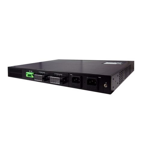
Table 3.18 Monitoring Descriptions of Network Access Server Switch Status ......................................................177
Table 3.19 Monitoring Descriptions of NAS Statistics Port 1 .................................................................................178
Table 3.20 Monitoring Descriptions of ACL Status.................................................................................................179
Table 3.21 Monitoring Descriptions of Dynamic ARP Inspection Table.................................................................180
Table 3.22 Monitoring Descriptions of Dynamic IP Source Guard Table...............................................................181
Table 3.23 Monitoring Descriptions of RADIUS Server Status Overview ..............................................................181
Table 3.24 Monitoring Descriptions of Each Port’s RADIUS Server Status ...........................................................182
Table 3.25 Monitoring Descriptions of RADIUS Authentication and Accounting Statistics....................................184
Table 3.26 Monitoring Descriptions of RMON Statistics Status Overview.............................................................186
Table 3.27 Monitoring Descriptions of RMON History Overview ...........................................................................187
Table 3.28 Monitoring Descriptions of RMON Alarm Overview .............................................................................188
Table 3.29 Monitoring Descriptions of RMON Event..............................................................................................189
Table 3.30 Monitoring Descriptions of Aggregation Status....................................................................................189
Table 3.31 Monitoring Descriptions of LACP System Status.................................................................................190
Table 3.32 Monitoring Descriptions of LACP Internal Port Status .........................................................................190
Table 3.33 Monitoring Descriptions of LACP Neighbour Port Status.....................................................................191
Table 3.34 Monitoring Descriptions of LACP Statistics..........................................................................................192
Table 3.35 Monitoring Descriptions of STP Bridges...............................................................................................193
Table 3.36 Monitoring Descriptions of STP Port Status.........................................................................................193
Table 3.37 Monitoring Descriptions of STP Statistics ............................................................................................194
Table 3.38 Descriptions of DHCP Server Statistics Monitoring..............................................................................195
Table 3.39 Monitoring Descriptions of IGMP Snooping Group Information...........................................................196
Table 3.40 Monitoring Descriptions IGMP SFM Information..................................................................................197
Table 3.41 Monitoring Descriptions of MLD Snooping Status................................................................................197
Table 3.42 Monitoring Descriptions of MLD Snooping Group Information.............................................................198
Table 3.43 Monitoring Descriptions of MLD SFM Information ...............................................................................199
Table 3.44 Monitoring Descriptions of LLDP Neighbour Information.....................................................................199
Table 3.46 Monitoring Descriptions of LLDP Global and Statistics Local Counters ..............................................200
Table 3.47 Monitoring Descriptions of PTP External Clock Mode and Clock Configuration..................................202
Table 3.48 Monitoring Descriptions of 802.1AS Statistics......................................................................................202
Table 3.49 Monitoring Descriptions of MAC Address Table...................................................................................203
Table 3.50 Monitoring Descriptions of VLAN Membership Status for Combined Users........................................204
Table 3.51 Monitoring Descriptions of VLAN Port Status for Combined Users .....................................................205
Table 3.52 Monitoring Descriptions of DDMI Overview..........................................................................................206
Table 3.53 Monitoring Descriptions of DDMI Detailed ...........................................................................................207
Table 3.54 Monitoring Descriptions of Detailed UDLD Status for Port 1 and Neighbour Status............................208
Table 4.1 Descriptions of Options for Ping (IPv4) Diagnostic Tool........................................................................209
Table 4.2 Descriptions of Options for Ping (IPv6) Diagnostic Tool........................................................................212
Table 4.3 Description of each parameter for Traceroute (IPv4) ............................................................................213
Table 4.4 Description of each parameter for Traceroute (IPv6) ............................................................................214
Table 5.1 Descriptions of Software Image Selection .............................................................................................219

Industrial Managed
Ethernet Switch –EH9711
User Manual
Page 13 of 223
1Introduction
1.1 Introduction to Industrial Managed Switch
Atop’s EH (Ethernet Hub) 9711 series are product lines of powerful industrial managed switch which are referred to as Open
Systems Interconnection (OSI) Layer 2 bridging devices. Unlike an “unmanaged” switch, which is normally found in homes
or in Small Office/Home Office (SOHO) environments and runs in “auto-negotiation” mode, each port on a “managed switch”
can be configured for its link bandwidth, priority, security, and duplex settings. The managed switches can be managed by
Simple Network Management Protocol (SNMP) software, web browsers, Telnet, or serial console. Since every single port can
be configured to specific settings, network administrators can better control the network and maximize network functionality.
Atop’s managed switch is also an industrial switch and not a commercial switch. A commercial switch simply works in a
comfortable office environment. However, an industrial switch is designed to perform in harsh industrial environments, i.e.,
extreme temperature, high humidity, dusty air, potential high impact, or the presence of potentially high static charges. Atop’s
managed switch works fine even in these environments.
Atop’s managed switch is designed to provide faster, secure, and more stable network. Advantages that make it a powerful
switch are that it supports security such as IP Source Guard, DHCP Snooping, ARP Inspection as well as Access Control List
(ACL) and network redundancy protocols/technologies such as Ethernet Ring Protection Switching (ERPS), Rapid Spanning
Tree Protocol (RSTP), and Multiple Spanning Tree Protocol (MSTP). These protocols provide better network reliability and
decrease recovery time.
Atop’s managed switch supports a wide range of IEEE standard protocols. This switch is excellent for keeping systems running
smoothly, reliable for preventing system damage or losses, and friendly to all levels of users. The goal of this innovative
product is to bring users an enhanced network management experience.
Note:
Throughout the manual, the symbol * indicates that more detailed information of the subject will be provided at the end of this
book or as a footnote.

Industrial Managed
Ethernet Switch –EH9711
User Manual
Page 14 of 223
1.2 Software Features
Atop’s industrial Layer-2 Managed switches come with a wide range of network protocols and software features. These
protocols and software features allow the network administrator to implement security and reliability into their network.
These features enable Atop’s switches to be used in safety applications, and factory and process automation. The followings
are the list of protocols and software features.
User Interfaces
oWeb browser
oTelnet Console
oSerial Console
Dynamic Host Configuration Protocol (DHCP) Snooping/Relay/Client
Time Synchronization
oNetwork Time Protocol (NTP) Client
oSimplified Network Time Protocol (SNTP)
oIEEE 1588 Precision Clock Synchronization Protocol (PTP) v2 hw-E2E TC and hw-sw-Boundary -> hw-
Boundary Clock
oSyncE
Port Mirroring
Quality of Service (QoS) Traffic Regulation
Link Aggregation Control Protocol (LACP)
Medium Access Control (MAC) Filter
GARP VLAN Registration Protocol (GVRP)
Internet Group Management Protocol (IGMP)/ Multicast Listener Discovery (MLD)
Simple Network Management Protocol (SNMP) v1/v2/v3
SNMP Inform
Spanning Tree Protocol (STP)/ Rapid Spanning Tree Protocol (RSTP)/ Multiple Spanning Tree Protocol (MSTP)
Virtual Local Area Network (VLAN)
IEEE 802.1x/ Extensible Authentication Protocol (EAP) / Remote Authentication Dial-In User Service (RADIUS) /
Terminal Access Controller Access-Control System (TACACS+)
Security feature including Port Security/ IP Source Guard/ ARP Inspection/ Access Control List (ACL)
Ring
oEthernet Ring Protection Switching (ERPS)
Link Layer Discovery Protocol (LLDP)
Alarm System (with E-mail Notification or Relay Output)
Industrial Protocols
oModbus/TCP
SD Backup
1.3 Introduction to the Document
There are total of six sections in this document: Introduction, Configuring with a web browser, Monitor, Diagnostics,
Maintenance. The first section introduces the device, the software features, and the document. The second section, configuring
with a web browser shows users the setting webpage and the meaning of each parameter. The third section, Monitor, allows
user to see the current status of the device. The forth section, Diagnostics, allows user to identify problems and troubleshooting
through ping and traceroute webpage. Lastly, the fifth section, Maintenance, will let user to restart the device, reset all settings
to the default values, as well as, upload software version and save/download/upload/activate/delete the current configuration.

Industrial Managed
Ethernet Switch –EH9711
User Manual
Page 15 of 223
2Configuring with a Web Browser
There are three ways to configure Atop’s Industrial Managed Ethernet Switch: Web browser, Telnet console, and Serial
console. How to access the industrial managed switch through web browser is explained in Chapter 2 through Chapter 5. There
are only a few differences among these three methods.The web browser and the telnet console methods allow users to access
the switch over the Internet or the Ethernet LAN, while the serial console method requires a serial cable connection between
the console and the switch.Users are recommended to configure the switch via a web browser because of its user-friendly
interface.
Next, we will proceed to use a web browser to introduce the managed switch’s functions. It is recommended to use Microsoft
Edge 103, Firefox 44, Chrome 48 or later versions. Below is a list of default factory settings. This information will be used
during the login process. Make sure that the computer accessing the switch are in the same subnet. That is the computer has an
IP address and the subnet mask same as the switch. Please pay attention when inputting the username and password, as they
are case sensitive.
IP Address: 10.0.50.1
Subnet Mask: 255.255.0.0
Default Gateway: 0.0.0.0
User Name: admin
Password: default
Before users can access the configuration, they have to log in. This can simply be done in the following steps.
1. Launch a web browser.
2. Type in the switch IP address (e.g. http://10.0.50.1), as shown in Figure 2.1).
Note: When the user name and the password are left empty, the login prompt will not show.
Figure 2.1 IP Address for Web-based Setting
3. The user can enter a Username and a Password to access the managed switch. Then, clicking on the Sign in
button.

Industrial Managed
Ethernet Switch –EH9711
User Manual
Page 16 of 223
Figure 2.2 Login page
4. If the user entered wrong passwords, users can try to re-enter the new username and password again until it is
correct. Or users can simply click the Cancel button to forfeit the process.
5. If the login process was success, the user will be presented with the Port State Overview webpage which shows
the front panel of the managed switch as shown in Figure 2.3.
Figure 2.3 Webpage after a successful login

Industrial Managed
Ethernet Switch –EH9711
User Manual
Page 17 of 223
2.1 System
This section describes how users can configure system information in details. Figure 2.4 shows submenus under the
ConfigurationSystem main menu.
Figure 2.4 Submenus under ConfigurationSystem Menu
2.1.1 Information
This subsection describes how users can assign system’s details to the Atop’s switch. There are three fields in this System
Information Configuration webpage: System Contact, System Name, and System Location. By entering this unique and
relevant system information, it will help identifying one specific switch among all the others in the network. However, the
switch must support a SNMP protocol. Figure 2.5 shows the System Information Configuration Webpage to an EH9711
managed switch model. Please click the “Save” button to update the information on the switch. Clicking on the Reset button
will undo any changes made locally and revert to previously save values. Table 2.1 summarizes the device information setting
descriptions and corresponding default factory settings.
Figure 2.5 System Information Configuration Webpage
Table 2.1 Description of the System Information Configuration
Label
Description
Factory Default
System Contact
Provides contact information for maintenance. Enter the
name of whom to contact in case a problem occurs. The
allowed string length is 0 to 255, and the allowed content
is the ASCII characters from 32 to 126.
Null
System Name
Specifies a particular role or application of different
switches. The name entered here will also be shown in
Atop’s Device Management Utility. By convention, this is
the node's fully-qualified domain name. A domain name is
a text string drawn from the alphabet (A-Za-z), digits (0-
Null

Industrial Managed
Ethernet Switch –EH9711
User Manual
Page 18 of 223
Label
Description
Factory Default
9), minus sign (-). No space characters are permitted as
part of a name. The first character must be an alpha
character. And the first or last character must not be a
minus sign. The allowed string length is 0 to 255.
System Location
The physical location of this node (e.g., telephone closet,
3rd floor). The allowed string length is 0 to 255, and the
allowed content is the ASCII characters from 32 to 126.
Null
2.1.2 IP
In this subsection, the user may modify network settings on Internet Protocol (IP) for the managed switch. This subsection is
divided into three parts: IP Configuration, IP Interfaces, and IP Routes, as shown in
Table 2.7. First, the IP Configuration part is related to how the managed switch will be operated as Host. The IP Interfaces
part is related to IP Address configuration and DHCP configuration for both IPv4 and IPv6. Finally, the IP Routes part
contains the routing table that provides information about the network destination, gateway, next hop, and distance.
Figure 2.6 Webpage to Configure System’s IP Information.
The first part as shown in Figure 2.6 allows the user to set the operating mode of the managed switch. The user can enter up
to four DNS Servers. A DNS (domain name system) proxy allows clients to set up device as a DNS proxy server. A DNS
proxy improves domain lookup performance by caching previous lookups. A typical DNS proxy processes DNS queries by
issuing a new DNS resolution query to each name server that it has detected until the hostname is resolved. Table 2.2
provides detailed description of each option in this part which is also called basic setting.

Industrial Managed
Ethernet Switch –EH9711
User Manual
Page 19 of 223
Figure 2.7 Webpage to Configure System’s IP Configuration
Table 2.2 Description of Basic Settings
Label
Description
Mode
Configure the IP stack to act as a Host, where IP traffic between interfaces will not be routed.
DNS Server
This setting controls the DNS name resolution done by the switch.
There are four servers available for configuration, and the index of the server presents the preference
(less index has higher priority) in doing DNS name resolution.
The following modes are supported:
- No DNS server: No DNS server will be used.
- Configured IPv4: Explicitly provide the valid IPv4 unicast address of the DNS Server in dotted
decimal notation. Make sure the configured DNS server could be reachable (e.g. via PING) for
activating DNS service.
- Configured IPv6: Explicitly provide the valid IPv6 unicast (except local link) address of the DNS
Server. Make sure the configured DNS server could be reachable (e.g. via PING6) for activating DNS
service.
- From any DHCPv4 interfaces: The first DNS server offered from a DHCPv4 lease to a DHCPv4-
enabled interface will be used.
- From this DHCPv4 interface: Specify from which DHCPv4-enabled interface a provided DNS
server should be preferred.
- From any DHCPv6 interfaces: The first DNS server offered from a DHCPv6 lease to a DHCPv6-
enabled interface will be used.
- From this DHCPv6 interface: Specify from which DHCPv6-enabled interface a provided DNS
server should be preferred.
DNS Proxy
When DNS proxy is enabled, system will relay DNS requests to the currently configured DNS server,
and reply as a DNS resolver to the client devices on the network.
Only IPv4 DNS proxy is now supported
The second part of IP Setting section is the IP Interface part as shown in Figure 2.8. The user can choose to enable DHCP
(Dynamic Host Configuration Protocol) for DHCPv4 and/or DHCPv6 by checking the box behind it. That is the IP address
and related information can be automatically obtained from a DHCP server in the local network thus reducing the work for an
administrator. By disabling this function (DHCP’s box is unchecked), the user has an option to setup the static IP address and
related fields manually. If DHCP is disabled, the user should enter the IP addresses and Max Length (subnet mask) under IPv4
and/or IPv6 columns. Table 2.3 provides detailed description of each option in this part of IP Interfaces.
Figure 2.8 Webpage to Configure System’s IP Interfaces
Table 2.3 Description of IP Interfaces’ Options
Label
Description
Delete
Select this option to delete an existing IP interface.

Industrial Managed
Ethernet Switch –EH9711
User Manual
Page 20 of 223
Label
Description
IF
The VLAN associated with the IP interface. Only ports in this VLAN will be able to
access the IP interface. This field is only available for input when creating a new
interface
DHCPv4 Enabled
Enable the DHCPv4 client by checking this box. If this option is enabled, the system
will configure the IPv4 address and mask of the interface using the DHCPv4 protocol.
DHCPv4 Client ID Type
This specified which of the three types below, i.e. IfMac, ASCII or HEX, shall be used
for the Client Identifier. See RFC-2132 section 9.14.
DHCPv4 Client ID ifMac
The interface name of DHCP client identifier. When DHCPv4 client is enabled and the
client identifier type is 'ifmac', the configured interface's hardware MAC address will
be used in the DHCP option 61 field.
DHCPv4 Client ID ASCII
The ASCII string of DHCP client identifier. When DHCPv4 client is enabled and the
client identifier type is 'ascii', the ASCII string will be used in the DHCP option 61
field.
DHCPv4 Client ID HEX
The hexadecimal string of DHCP client identifier. When DHCPv4 client is enabled and
the client identifier type 'hex', the hexadecimal value will be used in the DHCP option
61 field.
DHCPv4 Hostname
The hostname of DHCP client. If DHCPv4 client is enabled, the configured hostname
will be used in the DHCP option 12 field. When this value is empty string, the field use
the configured system name plus the latest three bytes of system MAC addresses as the
hostname.
DHCPv4 Fallback
The number of seconds for trying to obtain a DHCP lease. After this period expires, a
configured IPv4 address will be used as IPv4 interface address. A value of zero
disables the fall-back mechanism, such that DHCP will keep retrying until a valid lease
is obtained. Legal values are 0 to 4294967295 seconds.
DHCPv4 Current Lease
For DHCP interfaces with an active lease, this column shows the current interface
address, as provided by the DHCP server.
IPv4 Address
The IPv4 address of the interface in dotted decimal notation.
If DHCP is enabled, this field configures the fall-back address. The field may be left
blank if IPv4 operation on the interface is not desired - or no DHCP fall-back address
is desired.
IPv4 Mask Length
The IPv4 network mask, in number of bits (prefix length). Valid values are between 0
and 30 bits for an IPv4 address.
If DHCP is enabled, this field configures the fall-back address network mask. The field
may be left blank if IPv4 operation on the interface is not desired - or no DHCP fall-
back address is desired.
DHCPv6 Enable
Enable the DHCPv6 client by checking this box. If this option is enabled, the system
will configure the IPv6 address of the interface using the DHCPv6 protocol.
DHCPv6 Rapid Commit
Enable the DHCPv6 Rapid-Commit option by checking this box. If this option is
enabled, the DHCPv6 client terminates the waiting process as soon as a Reply message
with a Rapid Commit option is received.
This option is only manageable when DHCPv6 client is enabled.
DHCPv6 Current Lease
For DHCPv6 interface with an active lease, this column shows the interface address
provided by the DHCPv6 server.
IPv6 Address
The IPv6 address of the interface. An IPv6 address is in 128-bit records represented as
eight fields of up to four hexadecimal digits with a colon separating each field (:). For
example, fe80::215:c5ff:fe03:4dc7. The symbol :: is a special syntax that can be used
as a shorthand way of representing multiple 16-bit groups of contiguous zeros; but it
can appear only once.
System accepts the valid IPv6 unicast address only, except IPv4-Compatible address
and IPv4-Mapped address.
The field may be left blank if IPv6 operation on the interface is not desired.
IPv6 Mask Length
The IPv6 network mask, in number of bits (prefix length). Valid values are between 1
and 128 bits for an IPv6 address.
The field may be left blank if IPv6 operation on the interface is not desired.
The third part of IP Setting section is the IP Routes part as shown in Figure 2.9. Description of each field or option is
summarized in Table 2.4. Please click on the Save button to update the IP configuration on the switch. A system reboot is
Table of contents
Other Atop Switch manuals

Atop
Atop EMG8305 Series Manual

Atop
Atop ABLELink EH2006 User manual

Atop
Atop EHG7504 Manual

Atop
Atop EH3305 Series User manual

Atop
Atop EMG8508 Series Manual

Atop
Atop EHG2408 Series Manual

Atop
Atop EH7506-4PoE-2SFP User manual

Atop
Atop EHG75 series User manual

Atop
Atop CloudProof M1000 serious User manual

Atop
Atop RHG7528 Series Manual
Popular Switch manuals by other brands

S+S Regeltechnik
S+S Regeltechnik Premasreg 716 Series Operating Instructions, Mounting & Installation

Dell
Dell PowerConnect W-IAP175P reference guide

HP
HP 316095-B21 - StorageWorks Edge Switch 2/24 Upgrade instructions

Niles
Niles MVCHUB4 Specifications

Otto
Otto ESP Hub PTT Instructions for use

MaxiiNet
MaxiiNet Vi30005 installation manual