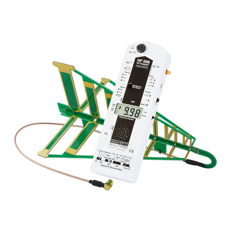
Digital High Frequency Analyser HF58B / HF58B-r / HF59B
© Gigahertz Solutions GmbH, 90579 Langenzenn, Germany
Page 5
fied accuracy of the used HF analyser due to
the narrowness of indoor spaces. According
to the “theory”, quantitatively accurate HF
measurements are basically only reproduci-
ble under so-called “free field conditions”,
yet we have to measure HF inside buildings
because this is the place where we wish to
know exposure levels. In order to keep sys-
tem-immanent measurement uncertainties as
low as possible, it is imperative to carefully
follow the measurement instructions.
As mentioned earlier in the introduction, even
slight changes in the positioning of the HF
analyser can already lead to rather substan-
tial fluctuations in measurement values. (This
effect is even more prevalent here than in the
ELF range.) It is suggested that exposure
assessments are based on the maximum
value within a locally defined area even
though this particular value might not exactly
coincide with a particular point of interest in,
for example, the head area of the bed.
The above suggestion is based on the fact
that slightest changes within the environment
can cause rather major changes in the power
density of a locally defined area. The person
who performs the HF testing, for example,
affects the exact point of the maximum val-
ue. It is quite possible to have two different
readings within 24 hours at exactly the same
spot. The maximum value across a locally
defined area, however, usually only changes
if the HF sources are subject to change. This
is why the latter value is much more repre-
sentative for the assessment of HF exposure.
The descriptions in the following mainly refer
to immission measurements, i.e. to the defi-
nition of the total power flux density relevant
for limit value comparisons.
In addition, this device can also be used to
identify the source of radiation, and – most
important – to determine appropriate shield-
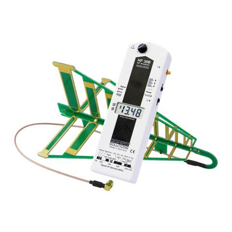
ing measures. The logper antenna which
comes with the meter is predestined for this
aim.
Preliminary Notes Concerning the An-
tenna
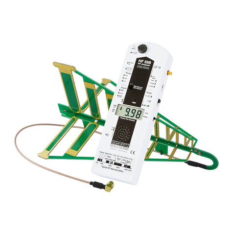
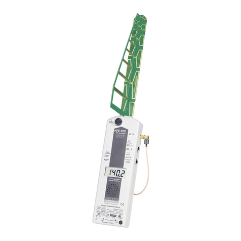
The supplied logarithmic-periodic antenna (or
aerial), has exceptional directionality. Thus
it becomes possible to reliably locate or “tar-
get” specific emission sources in order to
determine their contribution to the total HF
radiation level. To know exactly the direction
from where a given HF radiation source origi-
nates is a fundamental prerequisite for effec-
tive shielding. Our logarithmic periodic an-
tenna, the “LogPer antenna”, provides a dis-
tinct division of the horizontal and vertical
polarization plane. Also the frequency re-
sponse is exceptional. There is a patent
pending for its design.
The missing directionality of standard tele-
scope antennae is one of the reasons why
they are not suited for reliable HF measure-
ments in building biology EMR.
Important:
As the LogPer Antenna provided with this
instrument is shielded against ground influ-
ences one should “aim” about 10 degrees
below the emitting source one wants to
measure. This is to avoid distortions of the
reading.
The upper edge of the foremost resonator is
a good “aiming aid” for the required angle. It
does not matter if the angle gets a little too
wide.
The readings from the instrument’s display
always reflect the integral power density at
the measurement location coming from the
direction the antenna is pointing at (i.e.
based on the spatial integral of the “antenna
lobe”).
The LogPer aerial supplied with the meter
covers a frequency range of approx. 800
MHz to 2700 MHz (= 2.7 GHz), i.e. cellular
phone frequencies (e.g. GSM900, GSM1800,
TDMA, CDMA, AMPS, iDEN), 2.4-GHz
(DECT) cordless phones, frequencies of third
and fourth generation (3G/4G) technologies,
such as UMTS, LTE, WLAN and Bluetooth,
as well as other commercial frequency bands
and microwave ovens. All the frequencies in
between are also included. This is the fre-
quency range in which you would find most
of the pulse-modulated signals concerned
scientists are worried about.
In order to avoid measurement values to be
falsified by radiation sources from frequen-
cies below 800 MHz when measuring with
the LogPer antenna, the HF58B and the
HF58B-r are equipped with an additional
internal high pass filter at 800 MHz, causing
these lower frequencies to be suppressed.
As the HF59B picks up frequencies below
800 MHz, it has no integrated high pass filter.
However the filter is available for external
connection if needed, and is to be placed
between the antenna entry and the antenna
cable.
