Preparations Prior to Testing
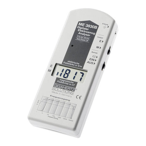
1. Check the field meter according to the instructions laid out under "Getting Started".
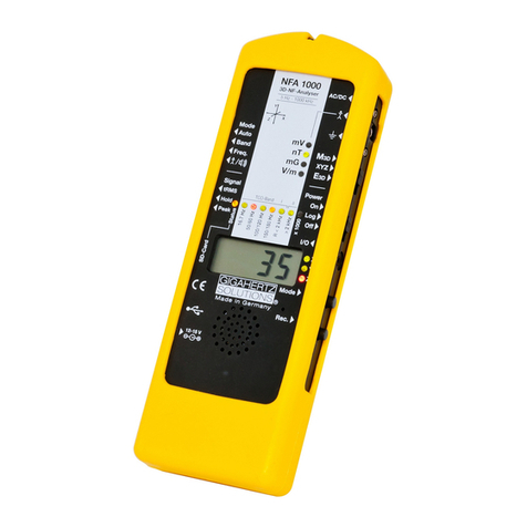
2. First of all take measurements of AC electric and magnetic fields outdoors to get a feel for the
background radiation. If the field meter registers more than 5 V/m or 5 nT (0.05 mG), this will
give you an idea of the background exposure. By means of turning off the circuit breakers in
the main panel, it is possible to determine which of the fields are caused from inside the house
and which ones from outside such as high-tension power lines, railway trails, pole-mounted or
surface transformers as well as neighboring houses/apartments. If external fields are suspec-
ted, their sources can be traced by moving the field meter into the direction of the highest rea-
dings.
3. When performing an EMR survey in homes or at workplaces, all typical electric appliances and
electronic devices should be turned on, also including those that come on only temporarily such
as refrigerators or storage space heaters (e.g. in adjoining rooms). By turning the various appli-
ances off and on, it is possible to locate the most important field sources.
4. A sketch of the area to be measured that shows the corresponding test results and allows for
a later analysis of the situation. Thus appropriate remediation strategies can be assigned.
5. Start with the measurement range "200 nT/Vm." Only if the display goes in overload because
of rather high ambient field strengths, switch to the higher range "2000 nT/Vm".
6. Ideally, all measurements are to be repeated during various times of the day and on different
days of the week in order to identify fluctuations.
7. The additional sound signal that is proportional to the field strength makes the detection of field
sources easy.
Measurement Instructions - AC Electric Fields
1. Grounding the Field Meter and the Person Performing the Testing
According to relevant guidelines (TCO, MPR II, TÜV), prior to any electric field testing the field
meter needs to be connected to ground potential through the supplied grounding lead in order to
obtain reliable, reproducible testing results. Without a proper connection to ground potential no
reliable statements on AC electric fields can be made.
Unvarnished, metal piping for water, gas or heating can be used
to connect the grounding lead with its grounding clip. As an alter-
native, a licensed electrician could also use an alligator clip to
establish a grounding connection through the grounding conduc-
tor in a grounded outlet. Warning: In case the phase conductor is
touched, an electric shock hazard may result.
Picture 06
9
© by GIGAHERTZ SOLUTIONS®GmbH, 90579 Langenzenn, www.gigahertz-solutions.com
Measurement Instructions

