Gira 0318 04 User manual

GIRA
Info
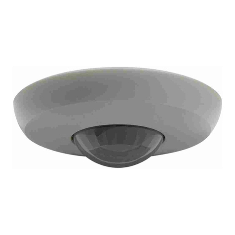
Radio-Control Presence Detector
Installation Instructions
Radio-Control Presence Detector 7/07 Page 1 of 15
1. Function
The radio-control presence detector (fig. 1.a) permits
to achieve optimal energy savings by controlling the
illumination of a room depending on the presence of
persons.
1.a)
The detector is equipped with a passive infrared sen-
sor (PIR) and responds to thermal movements trig-
gered by persons, animals or objects. The detector
transmits a radio data telegram which can be pro-
cessed by all radio-controlled dimming and switching
actuators from release R2 onwards (see. identifica-
tion on actuator).
The presence detector activates a programmed ra-
dio-control actuator whenever the ambient brightness
drops below an adjustable reference brightness and
whenever movements are detected. The actuator
then controls the light intensity depending on the re-
ference brightness.
The light control remains activated as long as the pre-
sence detector detects movements.
If no movements are detected anymore, the detector
switches off after the preset shut-off delay. The detec-
tor is equally switched off when the upper brightness
limit is exceeded. .
For monitoring of large areas, several presence de-
tectors can be used in common in the same system.
In this case, one presence detector works as the mas-
ter unit (main unit) whereas all other presence detec-
tors work as slave units (extension units).
Description
The radio presence detector consists of:
csensor window with LED
dornamental ring
ebaseplate
fpushbutton
Under ornamental ring d, the detector has 3 controls
for the setting of:
gsensitivity
hshut-off delay
ibrightness reference
1.b)
Radio-Control Presence Detector Order no.: 0318 02 / 0318 04
iImportant:
If the user wants the light control to be active imme-
diately after a person enters the monitored surface,
it is recommended to switch on the light control by
hand (cf. chapter 6.2 and 7.2) as it will otherwise take
a few seconds until the light control is activated by
the presence detector.
The reason for this is that - to avoid false triggering -
the detector’s sensitivity is initially reduced as com-
pared to that of a movement detector.

GIRA
Info
Radio-Control Presence Detector
Installation Instructions
Radio-Control Presence Detector 7/07 Page 2 of 15
2. Fitting and start-up
Place of fitting
The presence detector is fitted under the room ceiling
and monitors the working surface below (fig. 2.a).
Fig. 2.b: the actual brightness measured at the detec-
tor dis composed of reflected artificial light cand
daylight eand depends on the reflection properties of
the working surface f.
2.a)
2.b)
Avoid direct sunlight into the sensor window. The sen-
sors might otherwise be irreparably damaged.
If needed, the detection field can be confined by
means of the mask supplied with the device (cf. sec-
tion 3).
Install the presence detector free from vibrations and
not in the immediate vicinity of heat sources (e.g.
lamps, radiators), fans or ventilation ducts. Lamps
cooling down after operation or draughts (e.g. caused
by open windows) might be detected and lead to un-
desired switching.
Fitting
Attach the presence detector to the baseplate only af-
ter having installed the batteries and programmed the
presence detector into a radio-control receiver.
To install the presence detector proceed as follows:
1. Fasten the baseplate to the room ceiling using the
screws supplied (fig. 2.c c).
2. Turn the presence detector on the baseplate ap-
prox. 45° counterclockwise until it is heard to en-
gage.
2.c)
iImportant note:
Please note that the number of radio presence detectors to be used inside a radio-control zone (zone in which
radio telegrams can be exchanged between subscribers) is limited. As all these devices react in the same way
to the same ambient conditions as, for instance, a sudden rise of the outside brightness level, and as they will
then begin transmitting telegrams, the probability of the telegrams interfering with one another and thus caus-
ing malfunctions is considerably increased.
Depending on ambient conditions, a number of more than 8 radio-control presence detectors may already be
sufficient to cause malfunctions.
Safety instructions
Attention: Electrical equipment must be installed and fitted by qualified electricians only.

GIRA
Info
Radio-Control Presence Detector
Installation Instructions
Radio-Control Presence Detector 7/07 Page 3 of 15
Batteries
The radio-control presence detector operates on 4 al-
kaline micro batteries (LR 03) (not included in the
scope of supply). Batteries of the carbon-zinc type
(R 03) must not be used.
Inserting / replacing the batteries
1. Detach the presence detector from the baseplate
by turning the device approx. 45° clockwise on the
baseplate (fig. 2.d).
2. Replace the old batteries located at the back of the
housing. Wait ca. 2 minutes (capacitor discharge
time) before inserting the new ones paying atten-
tion to correct polarity (fig. 2.e).
3. Refit the presence detector on the baseplate by
turning the device approx. 45° counter-clockwise
until it is heard to engage
4. After insertion of the batteries, the device starts
transmitting programming telegrams for ca. 30
seconds.
To avoid undesired programming make sure that
none of the actuators is in the programming mode
during this time.
2.d)
2.e)
Programming a detector into a radio-control
receiver
For light control applications, the presence detector
must be programmed into only one radio-control re-
ceiver. The programming information is stored in the
radio-control receiver only.
During programming of a radio-control presence de-
tector, the sensitivity of the radio-control receivers is
reduced to approx. 5 m. The distance between the re-
ceiver and the radiocontrol presence detector should
therefore be not less than 0.5 m and not more than 5
m.
Programming procedure
1. When programming the first presence detector into
the radiocontrol receiver make sure the brightness
control (fig. 2.f i) does not point to the „Moon“
symbol. A presence detector with this setting will
be identified as a slave unit and can therefore not
be programmed as first unit into a radio-control re-
ceiver.
For programming of a presence detector system
(master/slave) please read also section 9.
2. Remove the battery for approx. 2 minutes from the
presence detector (capacitor discharge time).
3. Switch the radio-control receiver into the program-
ming mode (see „Radio-control receiver“ operating
instructions).
4. Put the battery back in place. The presence detec-
tor now starts transmitting special programming in-
formation telegrams for approx. 30 seconds. The
receiver confirms the programming cycle (see „Ra-
dio-control receiver“ operating instructions).
5. Switch the radio-control receiver back to the opera-
ting mode (see „Radio-control receiver“ operating
instructions).
2.f)
Safety and disposal instructions
Attention: Keep batteries away from children.
Remove used batteries immediately and discard
without polluting the environment.
Replace battery by identical or equivalent types
only.

GIRA
Info
Radio-Control Presence Detector
Installation Instructions
Radio-Control Presence Detector 7/07 Page 4 of 15
Deleting a detector in the radiocontrol receiver
An already programmed presence detector can be
deleted by starting a new programming cycle in the
radio-control receiver.
3. Field of detection and snap-on mask
The presence detector has a detection field of 360°.
The PIR sensors are arranged in 6 detection levels
with 80 lenses.
The detection range is ca. 5 m in diameter at desk
height (ca. 80 cm).
The diameter of the detection field at floor level is ca.
8 m.
These values are valid for installation under the ceil-
ing and a fitting height of 2.5 m.
For fitting heights above 2.5 m, the detection field in-
creases whereas the detection density and the sensi-
tivity are reduced.
3.b)
Snap-on mask
The snap-on mask supplied with the detector can be
used to blank out undesired zones of detection.
The mask is snapped onto the sensor window. Cut
out the mask only along the marked lines (fig. 3.c).
The following data are referred to a fitting height of ca.
2.50 m. In this case, the detection field on the floor
has a diameter of ca. 8.00 m.
3.c)
Cutting out the mask changes the diameter of the de-
tection field on the floor as follows:
Full mask without cutouts, sector I: Ø ca. 2.20 m
Sector II cut out: Ø ca. 4.00 m
Sectors II and III cut out: Ø ca. 6.00 m
Without mask: Ø ca. 8.00 m
The size of the detection field can be checked when
the detector works in the movement test mode.
iImportant
The radio-control presence detector cannot be ope-
rated together with a radio-control detector. For this
reason, it is essential that this transmitter has not
been programmed into the corresponding receiver
before the presence detector is programmed. If this
is the case, it must be deleted beforehand.
Programming of the presence detector is otherwise
not possible and the radio-control receiver remains
in the programming mode.

GIRA
Info
Radio-Control Presence Detector
Installation Instructions
Radio-Control Presence Detector 7/07 Page 5 of 15
4. Settings
To vary the brightness, the shut-off delay and the sen-
sitivity start by removing the ornamental ring (fig. 4.a
d) from the presence detector to gain access to the
controls.
4.a)
gSensitivity „sens“
The potentiometer permits adjusting the sensitivity of
the sensor between maximum and minimum.
When the sensitivity control is at minimum, the pre-
sence detector does not respond to movements.
hShut-off delay „time“
The potentiometer permits adjustment of the shut-off
delay for automatic operation in fine steps between
approx. 2 minutes and 1 hour. The center position
corresponds to 15 minutes.
Recommendation:
For smaller rooms, a shut-off delay of approx. 5 mi-
nutes is recommended.
For larger rooms, a longer delay should be chosen.
iReference brightness „lux“
The potentiometer permits the adjustment of refer-
ence brightness values in fine steps between approx.
3 lux (moon symbol) to approx. 2000 lux (sun sym-
bol). The center position corresponds to approx. 100
lux. The setting is taken over by the radio actuator
only after activation of the „light control test mode“.
After performing the setting put the ornamental ring
back in place. The protruding light sensor must fit into
the corresponding recession in the ornamental ring.
5. Setmodes
5.1 Light-control test mode
The light control test mode is used to preset the refer-
ence brightness of the presence detector. Fine tuning
can be done later by remote control when suitable ra-
dio-control transmitters have been programmed. For
dimming actuators refer to section 6.5 and for switch-
ing actuators to section 7.5.
In this mode, the detector does not detect move-
ments, but permits fast adjustment of the actual/refer-
ence brightness values (light control).
The reference brightness preset on the detector is
transmitted to and stored in the radio-control receiver.
The radio-control receiver compares the actual bright-
ness value transmitted to the reference brightness
stored and performs a light control.
Setting the reference brightness:
Important
The presence detector must have been programmed
beforehand into the radio-control receiver.
1. Depress button (5.a f) for at least 1 second. LED
(5.a c) first flashes up 10 times in a fast sequence
and then periodically every 5 seconds. The pre-
sence detector is now for approx. 5 minutes in the
light-control test mode.
5.a)

GIRA
Info
Radio-Control Presence Detector
Installation Instructions
Radio-Control Presence Detector 7/07 Page 6 of 15
2. Adjust the reference brightness value on the pre-
sence detector (fig. 5.b i) in such a way that the
resulting level of illumination in the room corres-
ponds to the desired lighting conditions (dimming
actuator) or that the light is switched on (switching
actuator).
For this setting it may be necessary to darken the
room.
Important:
With dimming acuators, the time required for
changing the reference brightness may be approx.
1 minute (brightness reference corresponds to ac-
tual brightness).
The light-control test mode ends automatically after
approx. 5 minutes or after a short (< 1 s) depression
of button (5.c f).
5.b)
5.c)
5.2 Movement test mode
In the movement test mode, the detection field of the
presence detector can be tested independently of the
brightness.
When the detector senses a movement in the move-
ment test mode, the programmed radio-control re-
ceiver will be activated for a fixed shut-off delay of 10
seconds.
Activating the movement test mode
To activate the movement test mode for about 10 mi-
nutes depress the button (fig. 5.c f) shortly (< 1 s).
In the movement test mode, the LED (fig. 5.c c) flash-
es 6 times during each transmission.
Deactivating the movement test mode
The movement test ends automatically after about 10
minutes or can be terminated by a brief depression (<
1 s) of the button.
6. Light control with a dimming actuator
A dimming actuator from Release 2 (R2) onwards can
be used to implement a light control function. For this
purpose, the dimming value in the actuator is adjust-
ed in such a way that the brightness measured at the
presence detector corresponds to the stored refer-
ence value.
In so far as the functions listed in sections 6.2 to 6.6
require a control operation, the respective commands
can be given by radio from the below-mentioned
transmitters (Fig. 6.a):
cHandheld transmitter ‘Komfort‘:
Channel key
dHandheld transmitter ‘Mini’
Channel key
eWall-mounted transmitter
Channel key
fMultifunction transmitter
Operating modes with doublesided actua-
tion of standard rocker pushbuttons
If used in conjunction with a radiocontrol push-button
for switching and dimming (fig. 6.a g), these func-
tions can also be operated locally.

GIRA
Info
Radio-Control Presence Detector
Installation Instructions
Radio-Control Presence Detector 7/07 Page 7 of 15
6.a)
6.1 Automatic mode
After a presence detector has been programmed into
a radio-controlled dimming actuator, the actuator ope-
rates permanently in the automatic mode.
If the actual brightness value measured at the pre-
sence detector is below the reference brightness, the
dimming actuator is started with full brightness
(100 %) when presence is detected.
Thereafter, the degree of dimming is adjusted in such
a way that the actual brightness corresponds to the
reference value (constant lightintensity control).
If the actuator is switched off and if the shut-off delay
is permanently retriggered by presence during the
switch-off phase, the actuator restarts with the lowest
dimming level when it is switched on again.
If - in the light control mode - no presence is detected
any more during the preset shut-off delay, the dim-
ming actuator shuts off, but remains in the automatic
mode.
The dimming actuator is also switched off at minimal
brightness and when the reference brightness is ex-
ceeded for at least 15 minutes by 40 %.
6.2 Manual activation of the light control
To activate the light control manually when the load is
switched off (without presence detection), depress
briefly a key on any of the radio-control transmitters
programmed into the radio-control.
If used with a radio-control pushbutton for switching
and dimming the light control can also be activated lo-
cally: when the presence detector is programmed into
the device, the light control can be terminated by de-
pressing briefly either the upper or the lower rocker of
the pushbutton.
6.3 Manual deactivation of the light control
An active light control (load on) can be deactivated by
a brief actuation of a programmed radio-control trans-
mitter.
Using a radio-control push-button for switching and
dimming also permits to deactivate the light control lo-
cally by hand: when the presence detector has been
programmed, the light control can also be terminated
by a brief depression of the upper or the lower rocker.
The actuator remains off as long as presence is being
detected (e.g. slide presentation). If no presence is
detected and a reset time of about 2 min. has elaps-
ed, the actuator will return to the automatic mode.
iImportant
When the actual brightness drops below the refer-
ence brightness during the shut-off delay, the load is
switched on even if no presence is detected.
iImportant
If no presence is detected for a period of at least 2
minutes after manual activation, the dimming actua-
tor is switched off.

GIRA
Info
Radio-Control Presence Detector
Installation Instructions
Radio-Control Presence Detector 7/07 Page 8 of 15
6.4 Temporary change of the reference
brightness setting
The reference brightness is adjusted at the presence
detector when the device is in the light-control test
mode (cf. section 5.1). This reference brightness can
be temporarily (or permanently, section 6.5) changed.
With a prolonged depression of a key (> 1 s) on a ra-
dio transmitter programmed into the dimming actuator
or by prolonged local actuation of a radio-control
push-button for switching and dimming, the bright-
ness of the connected lamps can be changed.
This new illumination level is temporarily stored in the
actuator as reference brightness until the next shut-
off. Since the storing procedure lasts about 1 minutes,
the new brightness level should be maintained con-
stant during ca. 1 minute.
6.5 Permanent change of the reference bright-
ness setting
When the temporary reference brightness has been
active for more than 2 minutes, it can be stored as
permanent reference brightness with a ‘Komfort’
model of the handheld transmitter programmed into
the dimming actuator.
Depress channel key 8 (/\ or \/) of channel group C
longer (> 1 s) (fig. 6.b).
With a radio-control push-button for switching and
dimming, the temporary reference brightness value
can be stored as permanent reference brightness
value by depressing both rockers together (double-
sided actuation) for at least 3 seconds when the lamp
is on (fig. 6.c)
This storage is confirmed by the LED at the dimming
actuator lighting up for approx 1 second or by a short
buzzing tone (lasting 0.5 seconds).
To go back to the reference brightness adjusted on
the presence detector, activate the light-control test
mode in the presence detector (cf. section 5.1).
6.b)
6.c)
6.6 Switching on / switching off for 2 hours
After a presence detector and a handheld transmitter
of the ‘Komfort’ type have been programmed into a
dimming actuator for light control, the additional func-
tions „Switching on for 2 hours“ and „Switching off for
2 hours“ can be selected.
Switching on for 2 hours (fig 6.d)
Depress channel key 7/\ of channel group C longer (>
1 sec.).
The pertaining dimming actuator is activated for 2
hours with 100 % brightness. In this state, it does no
longer respond to telegrams from the presence detec-
tor. When the 2 hours have passed, the presence de-
tector goes back to automatic operation.
6.d)

GIRA
Info
Radio-Control Presence Detector
Installation Instructions
Radio-Control Presence Detector 7/07 Page 9 of 15
Switching off for 2 hours (fig. 6.e)
Depress channel key 7\/ of channel group C longer (>
1 s).
The pertaining dimming actuator is switched off for 2
hours. In this state, it does no longer respond to tele-
grams from the presence detector.
When the 2 hours have passed, the presence detec-
tor goes back to automatic operation.
6.e)
To cancel these additional functions, depress a key
on a programmed radiocontrol transmitter briefly
(< 1 s)
With a radio-control push-button for switching and
dimming these additional functions can also be can-
celled by a brief depression of the upper or lower part
of the rocker.
If these additional functions are terminated by ‘switch-
ing on’, the dimming actuator switches on for at least
2 minutes. When no presence is detected and after a
retention time of appr. 2 minutes has elapsed, the
dimming actuator switches off and returns to automa-
tic operation.
If the additional functions are terminated by ‘switching
off’, the dimming actuator switches off for at least 2
minutes. It returns to automatic operation when no
presence is detected anymore and after a fixed reten-
tion time of 2 minutes has elapsed.
7. Light control with a switching actuator
A radio-control switching actuator from Release 2
(R2) onwards offers the possibility of implementing a
two-point light control with ON and OFF as the only
two switching states available.
In so far as the functions listed in sections 7.2 to 7.3
require a control operation, the respective commands
can be given by radio from one of the below men-
tioned transmitters (fig. 7.a):
cHandheld transmitter ‘Komfort’ :
Channel key
dHandheld transmitter ‘Mini’
Channel key
eWall-mounted transmitter
Channel key
fMultifunction transmitter
Operating modes with doublesided actuation of
standard rocker pushbuttons
7.a)
If used with a radio-control pushbutton for switching
and dimming (fig. 7.b g), these functions can also be
operated locally.
7.b)

GIRA
Info
Radio-Control Presence Detector
Installation Instructions
Radio-Control Presence Detector 7/07 Page 10 of 15
7.1 Automatic operation
When a presence detector has been programmed
into a radio-controlled switching actuator, the actuator
in question is permanently in the automatic operation
mode.
When the actual brightness measured at the radio-
control presence detector is below the reference val-
ue, the actuator is switched on when a movement is
detected. If no movement is detected anymore, the
presence detector switches the actuator off after the
adjusted shut-off delay.
When the measured actual brightness exceeds the
current reference brightness for approx. 15 minutes
by more than 100 %, the switching actuator is also
switched off. It is restarted on detection of movements
if the actual brightness measured at that time is below
the reference brightness.
7.2 Manual light control activation
Manual activation of the light control is the same as
described for the dimming actuator (see section 6.2).
7.3 Manual light control deactivation
Manual deactivation of the light control is the same as
described for the dimming actuator (see section 6.3).
7.4 Switching on and off for 2 hours
Switching on and off for 2 hours with a switching ac-
tuator is the same as described for the dimming actu-
ator (cf. section 6.6).
7.5 Permanent change of the brightness
reference value
The current actual brightness can be stored in the
dimming actuator as permanent reference brightness.
This value overwrites the reference brightness adjust-
ed manually on the presence detector
- with a handheld transmitter ‘Komfort’:
Depress channel key 8 (/\ or \/) of channel group C
longer (> 1 s) (fig. 7.c).
7.c)
-with a radio-control push-button for switching
and dimming
Depress both buttons at the same time for at least 3
seconds while the lamp is on (double-sided actua-
tion) (Fig. 7.d).
7.d)
This storage is confirmed by the LED at the dimming
actuator lighting up for approx 1 second or by a short
buzzing tone (lasting 0.5 seconds).
To go back to the reference brightness adjusted on
the presence detector, activate the light-control test
mode in the presence detector (see section 5.1)
iImportant
If the light begins to ‘toggle’ when a switching actua-
tor is used (lamp goes permanently on and off), the
brightness reference value must be increased.
When the actual brightness drops below the refer-
ence brightness during the shut-off delay, the load is
switched on even if no presence is detected.
iImportant
A temporary change of the reference brightness is
not possible when a switching actuator is used.

GIRA
Info
Radio-Control Presence Detector
Installation Instructions
Radio-Control Presence Detector 7/07 Page 11 of 15
8. Lightscape operation All-ON / All-OFF
During the retention time, the radio-controlled actua-
tor involved in light control can be integrated together
with other radio-controlled actuators into lightscapes
and into the ALL-ON or ALL-OFF function. The re-
called lightscape is statical, i.e. there is no light control
function.
The lightscapes can be recalled, stored and changed
with a handheld transmitter ‘Komfort’, a wall-mounted
transmitter or a multifunction transmitter. Read the
corresponding transmitter operating instructions.
Lightscape
A recalled lightscape will be switched on for at least 2
minutes with the actuator integrated into light control.
If no presence is detectec anymore and after elapsing
of the preset retention time, the actuator switches off
and returns to automatic operation.
All-ON
When a programmed All-ON key is pressed, the actu-
ator integrated into light control switches on. If no pre-
sence is detected anymore and after elapsing of the
preset retention time, the actuator switches off and re-
turns to automatic operation.
All-OFF
When a programmed All-OFF key is pressed, the ac-
tuator integrated into light control switches off for at
least 2 minutes. If no presence is detected anymore
and after elapsing of a fixed retention time of 2 min-
utes, the actuator switches off and returns to automa-
tic operation.
.
Master key special functions during lightscape
operation
The special functions during lightscape operation list-
ed below can only be operated with the Master key of
a handheld transmitter ‘Komfort’ or a wallmounted
transmitter with 4 channels.
Master key
- Handheld radio-control transmitter ‘Komfort’
When a lightscape key (fig. 8.a c) is programmed,
the Master key (fig. 8.a d) is automatically stored
in the radio-control receiver.
8.a)
- 4-channel wall-mounted radio control trans-
mitter
When at least one of channel keys 1 through 3 of
the 4-channel wallmounted transmitter is set for
lightscape operation and accordingly programmed
in the actuator, channel key 4 (fig. 8.b e) is auto-
matically assigned in the radiocontrolled actuator to
lightscape operation with Master key functions.
8.b)
iImportant
When a multifunction transmitter is used it is neces-
sary after recalling of a lightscape to wait until the
shut-off delay has passed before it is possible to re-
turn to the light control mode. Switching off the light-
scape earlier with a multifunction transmitter is not
possible.

GIRA
Info
Radio-Control Presence Detector
Installation Instructions
Radio-Control Presence Detector 7/07 Page 12 of 15
Functional description
The functions of the Master key are linked with the
lightscape key last operated. The following special
functions can therefore only be executed when the
lightscape key last operated is programmed in the ac-
tuator. If this is not the case, a brief depression of the
Master key starts the light control.
Handheld:
brief depression (< 1 s) of the left /\ key (8.c)
Wall-mounted:
brief depression of key 4+ (8.d)
At first, all actuators are switched to 100 % bright-
ness, i.e. ON, thereafter the light control starts up only
with the actuator assigned to light control.
Handheld:
brief depression (< 1 s) of the right \/ key (8.e)
Wall-mounted:
brief depression of key 4- (8.f)
The lightscape is switched off and remains in this
state as long as presence is detected (e.g. slide
show). This is only possible when the lightscape key
last pressed is programmed in the actuator.
If no presence is detected and after the shut-off delay
of 2 minutes has passed, the actuator involved in light
control returns to automatic operation.
Returning to automatic is also possible by depressing
briefly a key of a programmed radio-control transmit-
ter.
8.c)
8.d)
8.e)
8.f)
Handheld:
long depression (> 1 s) of the left /\ key (8.c)
Wall-mounted:
long depression of key 4+ (8.d)
The brightness of the whole active lightscape is in-
creased (no light control).
Handheld:
long depression (> 1 s) of the right \/ key (8.e)
Wall-mounted:
long depression of key 4- (8.f)
The brightness of the whole active lightscape is re-
duced (no light control).
Important:
A brief or prolonged depression of the Master key pro-
duces no reaction when the lightscape is off.

GIRA
Info
Radio-Control Presence Detector
Installation Instructions
Radio-Control Presence Detector 7/07 Page 13 of 15
9. Presence detector system (Master/Slave)
If larger areas are to be monitored, it is also possible
to use several presence detectors together in the
same system. In the presence detector system one
presence detector must be specified as the master
unit whereas all other detectors are used as slave
units.
Reference brightness value
The desired reference brightness is adjusted on the
master unit and is then valid for the whole system.
In all other presence detectors (slaves), the reference
brightness must be set to minimum (moon symbol
(fig. 9.).
Shut-off delays
The shut-off delay can be adjusted separately on all
presence detectors used. If an actuator is switched by
a presence detector, the shut-off delay of this device
starts running.
9.)
Programming the presence detectors
When programming the presence detectors into the
radio-control receiver (cf. section 2 „Programming a
detector into a radio-control receiver“) make sure the
presence detector specified as master unit is pro-
grammed first. The brightness reference control must
therefore not be set to minimum (moon symbol) since
the detector would otherwise be identified as slave,
which means that it cannot be programmed as the
first unit into an actuator.
The slave detectors can only be programmed thereaf-
ter. In the slaves, the brightness reference must be
set to minimum (moon symbol).
If a master has already been programmed, any fur-
ther programming of a master overwrites the previous
one, i.e. only one unit can be stored as master detec-
tor.
10. LED and LowBatt indicator
The LED behind the sensor window (fig. 10. c) flash-
es up briefly 3 times during each transmission.
In the movement test mode, the LED flashes 6 times
during each transmission.
If the LED flashes ca. 10 times during a transmission,
the batteries are almost empty (LowBatt) and should
be replaced (cf. section 2 „Inserting/replacing the bat-
teries“).
10.)

GIRA
Info
Radio-Control Presence Detector
Installation Instructions
Radio-Control Presence Detector 7/07 Page 14 of 15
11. Radio Transmission
Radio transmission takes place on a non-exclu-
sive path.
Therefore, interference cannot be excluded. This
type of radio transmission is not suitable for safe-
ty applications such as emergency stops or emer-
gency calls.
The range of a radio-control system depends on
transmitter power, receiver characteristics, air humi-
dity, fitting height and building conditions.
The figure illustrates the penetration of building ma-
terials by radio waves:
Dry material Permeability
Timber, gypsum, gypsum-
plasterboards approx. 90 %
Brickwork, particle boards approx. 70 %
Reinforced concrete approx. 30 %
Metal, metal grating,
aluminium lamination approx. 10 %
Rain, snow approx. 0 - 40%
11.)
12. Technical specifications
Nominal voltage: 6 V DC
Batteries: 4x1,5 V Micro LR03 (AAA)
Alkaline
Note: Never use carbon-zinc batteries (R 03) or
rechargeable batteries.
Transmit frequency: 433.42 MHz
Modulation: ASK
Transmitting range: max. 100 m free field
Coding: > 1 billion
Angle of detection: 360°
Nominal range
- at desk level: approx. Ø5 m
- at floor level: approx. Ø8 m
Fitting height for nominal range: 2.5 m
Shut-off delay: approx. 2 min-1 h
Brightness: approx. 3-2000 lx
Temperature range: 0 °C ... 45 °C
Degree of protection: IP 20
Dimensions
- diameter: 103 mm
- height: 42 mm
iRadio operation
• The inter-connection of this radio system with other communication networks must comply with national le-
gislation.
• This radio system must not be used for communication beyond property boundaries.
• Operation in Germany is subject to the relevant regulations (Amtsblatt Vfg 73/2000).
• If utilized in conformity with its designated use, this unit fulfills the requirements of the R&TTE Directive
(1999/5/EG). The complete declaration of conformity can be found in the internet under:
www.gira.de/konformitaet
The presence detector may be operated in all EU and EFTA countries.

GIRA
Info
Radio-Control Presence Detector
Installation Instructions
Radio-Control Presence Detector 7/07 Page 15 of 15
N.B.
An adhesive label with the preset special light control
functions for radio-control transmitters (Fig. 12.)
‘Komfort’ is supplied with the detector.
12.)
Acceptance of guarantee
We accept the guarantee in accordance with the corresponding legal provisions.
Please return the unit postage paid to our central service department giving a brief description of the
fault:
Gira
Giersiepen GmbH & Co. KG
Service Center
Dahlienstrasse 12
D-42477 Radevormwald
Gira
Giersiepen GmbH & Co. KG
Postfach 1220
D-42461 Radevormwald
Telefon: +49 / 21 95 / 602 - 0
Telefax: +49 / 21 95 / 602 - 339
Internet: www.gira.de
This manual suits for next models
1
Table of contents
Other Gira Security Sensor manuals

Gira
Gira 2399 02 User manual

Gira
Gira System 3000 User manual

Gira
Gira 2050 Series User manual

Gira
Gira System 3000 User manual

Gira
Gira 5373 Series User manual

Gira
Gira 2105 02 User manual

Gira
Gira Cube 120 User manual

Gira
Gira Cube 240 2194 Series User manual

Gira
Gira Tectiv 220 User manual

Gira
Gira System 3000 5373 Series User manual