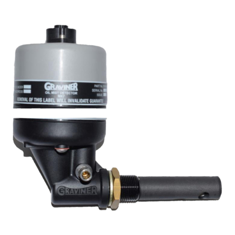
OIL MIST DETECTOR WARRANTIES
1. Carrier Fire & Security UK Ltd (Carrier) warrants, for a period of 3 years from the handover of the new
vessel which is installed with Graviner Mk6 Oil Mist Detector (OMD) system to the system owner, and
for a period of 2 years from the commissioning(*) date of a retro fitted Mk6 Oil Mist Detector (OMD)
system, that any component forming part of the original OMD system manufactured by or supplied by
Carrier shall be free from defects in workmanship or materials during normal usage
ent does not conform to this warranty Carrier will, at its sole
discretion and its cost, either repair or replace such component. Installation of the repaired /
replacement parts is not covered under the OMD System Warranty. Components replaced or repaired
under the terms of the OMD System Warranty shall continue to have the benefit of the unexpired
portion of the OMD System Warranty, unless that unexpired portion is less than 12 months, in which
case the repaired / replacement parts shall have the benefit of a 12 month warranty against defects
in workmanship or materials during normal usage starting on the date of delivery. OMD s supplied as
spares shall be warranted in accordance with paragraph 2 below only.
2. Carrier warrants for a period of 12 months from delivery that individual OMD s supplied as spares
shall be free from defects in workmanship or materials during normal usage.
3. Performance of Carrier
Carrier's liability under
4. The Warranties shall not apply to the following:
a. defects reasonably judged by Carrier as being caused by the improper installation of the OMD s
and/or OMD system;
b. defectsreasonablyjudgedbyCarrier asbeingcausedbythefailureto followtherecommendations
contained in Carrier frequency of
routine maintenance and testing of the OMD s and/or OMD system and/or the failure to have such
routine maintenance performed;
c. defects which are attributable to careless handling or storage, accident, improper use of the
OMD s and/or OMD system, or incorrectly completed repairs or routine maintenance services;
d. damages or losses occurring as a result of any act or omission which is wilfully unlawful or
negligent;
e. defects arising from the use of non-genuine Carrier parts or accessories, or the use of materials
not approved for use by Carrier;
f. any modifications to or installations performed on the OMD s and/or OMD system outside the
scopeofnormalroutinemaintenanceorrunningrepairswithouttheexpresspriorwrittenapproval
of Carrier;
g. deterioration, staining or corrosion of parts which will occur due to normal exposure and usage;
h. alleged defects not materially affecting the quality or proper functioning of the OMD system.
5. In addition, the Warranties shall be limited as follows:
a. Carrier shall be under no liability in respect of any defect in the OMD s and/or OMD System arising
from any drawing, design or specification supplied by or at the request of the buyer or system
owner (not being a drawing, design or specification of Carrier);
b. Carrier shall be under no liability in respect of any defect or failure of the OMD s and/or OMD
System to operate in accordance with specifications, illustrations, descriptions or other
particulars due to their combination or use with any incompatible equipment or product.
