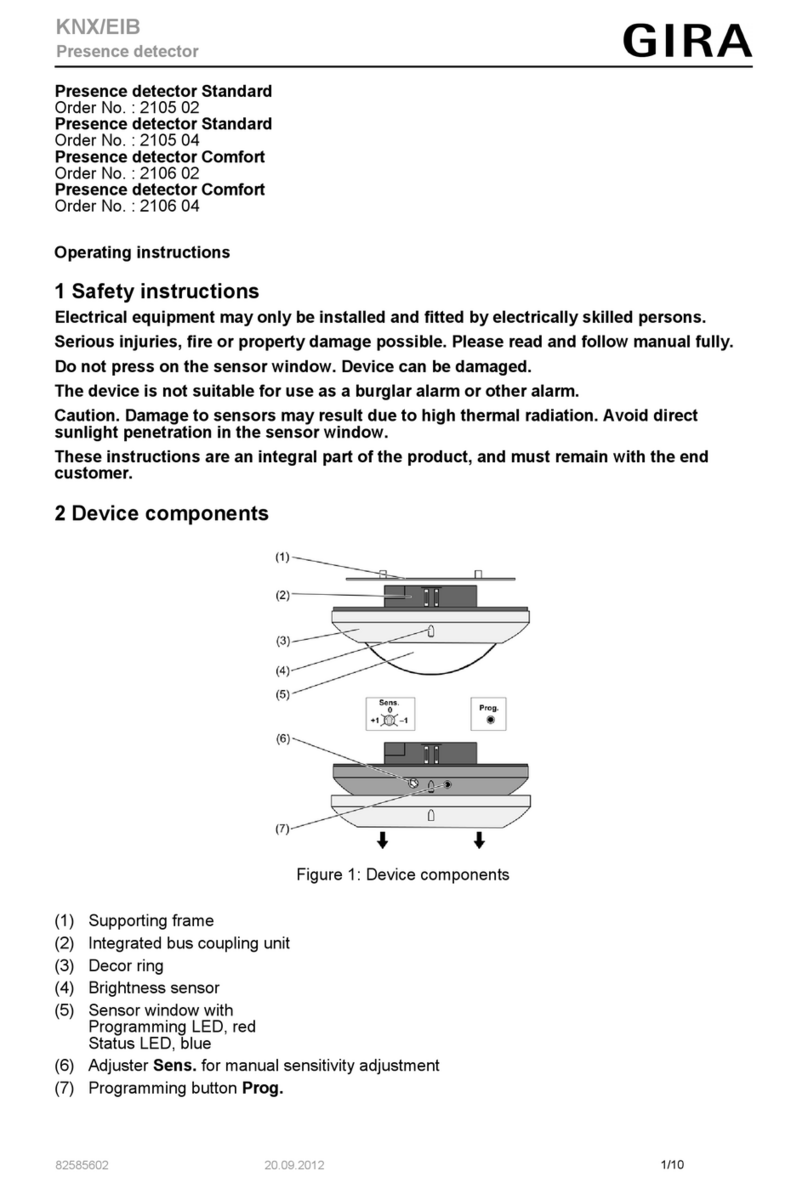
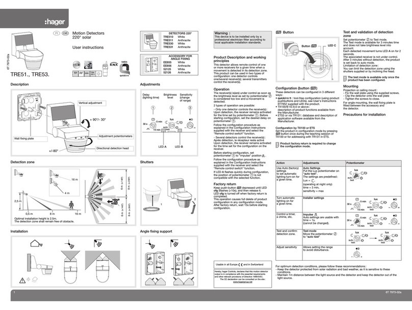
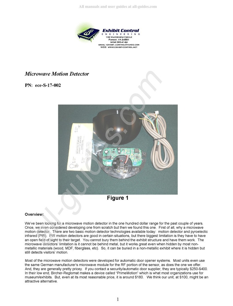
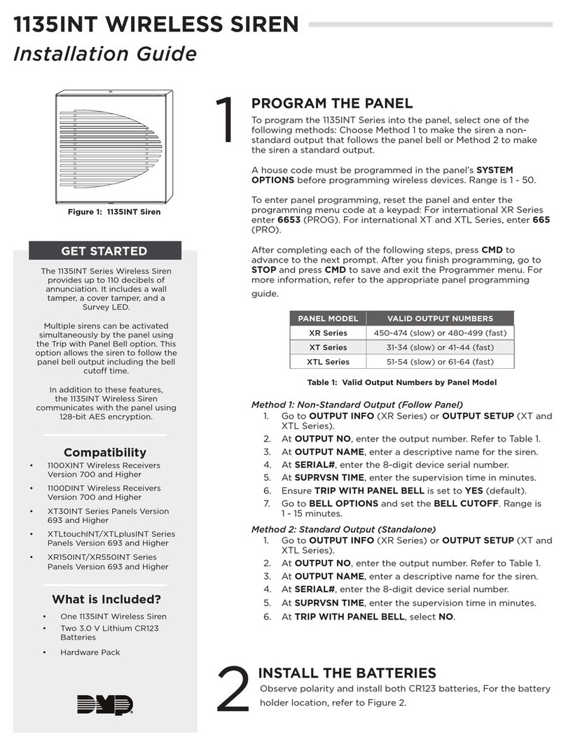
Gira 180 plus User manual

GIRA
Info Observer 180 plus
Installation Instructions
Observer 180 plus 28/99 Page: 1 of 13
Observer 180 plus Order No.: 0830 02
Theory of Operation
This observer responds to thermal movement initiated by persons, animals or objects and, when
detecting, turns on consumers such as lights.
The unit remains activated as long as movements are detected. Otherwise, the observer switches off
after a preset delay time has elapsed.
A visual signal indicates the responding of the unit.
With the aid of an adjustable twilight switch, the switching function is activated from a desired
brightness value only or can be set to day-time/night-time operation.
The working range of the unit can be individually adapted by adjusting the sensitivity.
Via a mechanical flush-mounted push-button (normally closed contact), the mode can be changed:
zObserver mode.
zLight ON for 2 hours.
zLight OFF for 2 hours.
zTest mode.
2
1
The working range of the unit can be reduced by a sensitivity
control.
A protective film cin front of lens system dmakes the units
weather-proof and dependable as well as guarantees a high quality
standard.
Detection Field
The observer has a dense, semicircular detection field consisting
of three levels with 144 switching segments.

GIRA
Info Observer 180 plus
Installation Instructions
Observer 180 plus 28/99 Page: 2 of 13
32m
16m
Detection field size: 16 m x 32 m,
please refer to the illustration.
The different grey zones in the illustration identify the three
observation levels.
2,4m
9m 3m16m
The three observation levels are defined as follows:
Near range from 0 m to approx. 3 m.
Medium range from approx. 3 m to approx. 9 m.
Far range from approx. 9 m to approx. 16 m.
The working range specified is referred to an installation height of
2.4 m, with the sensor head not tilted, the movement direction
lateral to the observer, and with a sufficient temperature difference
between the moving body and the environment.
Choosing the Location
To obtain an optimum working range, install the observer at a
height of 2.4 m, laterally to the moving direction, as, otherwise,
losses in the working range will have to be encountered.
Mind sources of interference such as animals, shrubs moved by
the wind, automotive vehicles or lamps within the range of
detection.
If necessary, restrict the sensor range of detection with the
attached slip-fit aperture.
Warning
Caution: The installation and assembly of electrical equipment
may only be performed by a skilled electrician.
Installation
All required screws and dowels are supplied with the unit.
Do not install directly above a lamp. A lamp cooling down may be
detected as a different heat rate and can lead to reclosing.
Choose a suitable place of installation. The detection field should
not be restricted by walls, fences, shrubs etc.

GIRA
Info Observer 180 plus
Installation Instructions
Observer 180 plus 28/99 Page: 3 of 13
Do not touch the sensor window.
Do not align the sensor window towards the sun. Sensors will be
damaged by the high thermal energy.
Install the observer in a vibration-free manner as sensor
movements may also initiate switching.
2
1
LN
Tilt the sensor head. Remove the central screw and open the unit.
Open condensed water hole cprior to installation (not when
installing the unit in dusty rooms).
The unit is provided with two cable entries.
The supply and lamp lines can be led into the enclosure
separately.
To lead in the lines, pierce respective rubber bushing d. Do not cut
open the rubber bushing too much. The cable sheath must be
firmly surrounded by the rubber bushing so that no water can
penetrate into the unit.
cd
Install the observer in such a way that condensed water hole c
and controls dare located below.
Fasten the unit to its place of installation with two screws.
1
For installation under ceilings, use the separate 'angle bracket' c
accessory item.
Attach the angle bracket to the ceiling with two screws and fit the
observer from behind with the central screw.

GIRA
Info Observer 180 plus
Installation Instructions
Observer 180 plus 28/99 Page: 4 of 13
2
1
3
For installation at building corners use the 'corner piece' d
(optional) accessory item.
Attach observer connection enclosure cto corner piece dby
central screw e, then mount the corner piece to the building corner
with two screws.
BK
BN
BU
Plug-in terminals have been provided by the manufacturer.
Terminal assignment:
BK (black): L
BU (blue): N
BN (brown): ↓
BK BU
BN
BK=L
BN=
BU=N
c
Connect the lines as shown in the wiring diagrams.
Lock the connection terminals into their holders cin the enclosure
bottom.
Plug on the enclosure top (sensor head) and secure with the
central screw.
cde
3 sec
1 min 5 min
15 min
ZEIT LUX SENS.
Test
Adjustments
Time setting (follow-up time) c
within the range of approx. 3 seconds to approx. 15 minutes.
Brightness setting d
within the range of approx. 3 - 80 lux and for day-time operation.
Recommended: Setting to 10 LUX - as shown in the illustration -
activates the unit at the beginning of dusk.
Sensitivity setting e
Sensitivity: Approx. 100% - 20%
reduction of the working range of the unit.
Adjust the sensitivity depending upon the tilt of the sensor head.
For a decreased detection range, the sensitivity should be re-
duced. First of all, select the highest sensitivity level as well as
determine and adjust the desired value by walking the detection
range during a function test.
Time

GIRA
Info Observer 180 plus
Installation Instructions
Observer 180 plus 28/99 Page: 5 of 13
cd
3 sec
1 min 5 min
15 min
ZEIT LUX SENS.
Test
e
Additional Functions
The mode can be changed via a mechanical flush-mounted push-
button (normally closed contact) (for connecting the push-button,
please refer to the wiring diagrams).
Coloured light-emitting diodes (LEDs) are located behind the time,
lux and sensitivity controls. These LEDs indicate what additional
function has been selected.
LED c:Green.
LED d:Red.
LED e:Red.
1st Additional Function
Pressing the push-button once: Observermode.
After activation, the observer switches on for the preset time irrespective of the brightness. Movements
will be detected and evaluated.
When the unit has switches off, movements are evaluated, depending upon the brightness.
Relay open: All LEDs are off.
Relay closed: LED cis lit.
2nd Additional Function
Pressing the push-button twice: Light ON.
The light is switched on for approx. 2 hours. After this, the unit changes to observer mode.
LED cand LED eare lit.
3rd Additional Function
Pressing the push-button three times: Light OFF.
The light is switched off for approx. 2 hours. After this, the unit changes to observer mode.
LED dis lit.
4th Additional Function
Pressing the push-button four times: Test mode.
Brightness evaluation is deactivated (day-time operation). The observer switches on for about 3
seconds when detecting a movement.
Relay open: LED
dand LED eare lit.
Relay closed: LED
cand LED dand LED eare lit.
For each operation, the push-button must be held pressed for at least 200 ms, while the next
operation must be done within 2 seconds. After this, the additional function selected will be
activated.
After mains voltage failure, the unit is in the observer mode (function 1).
Time

GIRA
Info Observer 180 plus
Installation Instructions
Observer 180 plus 28/99 Page: 6 of 13
Intelligent Limit Function
Once the observer has switched on, the brightness is no longer evaluated. The lamps shine on the
brightness sensor, the preset brightness value might be exceeded, and the observer would switch off.
So as not to keep the lighting continuously switched on when movements permanently take place
within the detection field (e. g. beyond dawn), the unit is provided with an intelligent limit function.
The follow-up time (the time when the light still remains on after no more movement has been
detected) is selected as a function of the real on period:
On period Follow-up time (approx.)
Up to 60 min. according to the setting
Up to 70 min. 4 min.
Up to 75 min. 2 min.
Up to 80 min. 1 min.
Up to 85 min. 30 sec.
Up to 90 min. 15 sec.
90 min. Switching-off
Thus, even in the event of permanent movements within the detection field, the observer switches off
after 90 min., at the latest.
Reclosing will only be triggered when the preset brightness value is undercut and a movement is
perceived within the detection field.
2
0
15
30
45
15
30
45
1
0
15
30
45
15
30
45
Detection Range - Adjustment
To adapt the detection field to the local conditions, the sensor head
can be tilted and turned.
To open and close the connection chamber, it might be necessary
to bring the turned sensor head to neutral position. For this
purpose, turning angle cand tilting angle dcan be read off scales
on the observer enclosure, the desired position being reproducible
any time.
Using the Slip-Fit Aperture
With the aid of the attached aperture, interference sources can be
eliminated by restricting the detection angle. For this purpose, cut
out the aperture and slip it onto the sensor head.

GIRA
Info Observer 180 plus
Installation Instructions
Observer 180 plus 28/99 Page: 7 of 13
1
2
Example
c: Masked area.
d: Observed area.
1
2
To mask the remote area, cut out the lower aperture blades only.
Example
c: Masked area.
d: Observed area.
If the detection angle of 180° is not required because of the local
conditions, the detection field should be restricted by the use of the
slip-fit aperture. Otherwise, undesired detection (e. g. thermal
movement through open windows) may entail erroneous switching.
cd
3 sec
1 min 5 min
15 min
ZEIT LUX SENS.
Test
e
Function Test
For the function test, the slip-fit aperture must be removed or cut
out to the desired angle of detection.
Select 'test mode' by pressing the push-button four times (please
refer to 'Additional Functions').
LED dand LED eare permanently lit. LED cindicates the
switching of the observer.
Check the alignment of the sensor head by walking the detection
field.
After the function test, activate 'observer mode' by pressing the
push-button once.
Time

GIRA
Info Observer 180 plus
Installation Instructions
Observer 180 plus 28/99 Page: 8 of 13
cd
3 sec
1 min 5 min
15 min
ZEIT LUX SENS.
Test
e
If no push-button for the additional functions has been installed for
the 180° observer, the test mode can also be set on the unit.
Select the following for the function test:
cTime setting: Approx. 3 sec.
dBrightness setting: Day-time operation.
eSensitivity: Individual, please refer to the illustration.
After the function test, you can set the time and brightness value
as desired.
Notes:
After the observer has switched off, a delay time of 3 seconds must be waited before switching on
takes place again.
Turning on the mains supply triggers a switching process of the observer. If this is not desired, please
install an additional switch, as shown in the connection diagram.
When the lighting is off, unfavourable installation conditions may cause reclosing by detection of the
lamps (cooling down and hence different heat rate), due to reflection of heat radiation from the lighting,
or due to too close a spacing between the observer and the lighting fixture. In this case, reduce the
sensitivity.
L
N
S
Wiring Diagrams
Existing Installation
BK BUBN
T
N
L
Connecting the Observer
Replace existing switch 'S' by additional functions push-button 'T'
(normally closed contact).
For each operation, the push-button must be held pressed for
at least 200 ms, while the next operation must be done within
2 seconds. After this, the additional function selected will be
activated.
BK (black): L
BU (blue): N
BN (brown): ↓
Time

GIRA
Info Observer 180 plus
Installation Instructions
Observer 180 plus 28/99 Page: 9 of 13
BK BUBN
N
L
T
S1 S2
Deactivating the Observer
Remove the observer from operation with switch S1 or S2.
When the observer is re-activated, switch S1 triggers a switching
process, whereas S2 does not.
BK (black): L
BU (blue): N
BN (brown): ↓
BK BU
BN
T
N
L
T
Two-Way Circuit:
Existing two-way switches may be replaced by 'T' push-buttons
(normally closed contact).
BK (black): L
BU (blue): N
BN (brown): ↓
BK BUBN
T
N
L
BK BU
BN
Connecting Several Observers
Parallel connection ('T' push-button, normally closed contact).
Note: Parallel connection will increase the maximum installed load.
BK (black): L
BU (blue): N
BN (brown): ↓
When observers are connected in parallel, only the presently active unit may possibly detect a
movement. If the room illumination switched on shines on further parallel units, these will not be
activated because of the high ambient brightness.
After the observer has switched off, the factory-set locking time of approx. 3 seconds must be waited.
Reclosing due to detecting a lamp cooling down is thus avoided.
Observers (individual or parallel units) which have not detected any movement are not locked, or their
locking time of 3 seconds has elapsed already.
When the lighting is switched off, reclosing may be caused by the detection of lamps (cooling and
hence different heat rate), due to reflection of heat radiation from the lighting, or due to too close a
spacing between the observer and the lighting fixture.

GIRA
Info Observer 180 plus
Installation Instructions
Observer 180 plus 28/99 Page: 10 of 13
Specifications
Rated working range: 16 m
Installation height: Approx. 2.40 m
Rated voltage: 230 VAC, 50 Hz
Switching contact: Relay
Starting current: Max. 20 A
Automatic cut-out: 10 A
Switching capacity:
Incandescent lamps 2500 W
Halogen HV lamps 2500 W
Fluorescent lamps
Unbalanced: 1200 W
Shunt-compensated: 920 W
Twin-lamp circuit: 2400 W
Important:
Mind high starting current peaks for 'energy-saving lamps'. Test the suitability of the lamps prior to
use.
Power consumption: Approx. 1.1 W
Temperature range: -25 °C to 55 °C
On period: Approx. 3 sec. to approx. 15 min., continuously adjustable
Brightness sensor:
Day-time and night-time operation Continuously adjustable
Sensitivity: Adjustable on approx. 20-100%
Additional functions: ON for 2 hours
OFFfor2hours
Testmode
Protective system: IP 55, hose-proof.
Connections: L,N,
↓
1.5mm²line
Please hand over these Operating Instructions to your Customer after installation.
These observers are not sabotage-proof and, therefore, not suitable for use as alarm system.

GIRA
Info Observer 180 plus
Installation Instructions
Observer 180 plus 28/99 Page: 11 of 13
2,4m
16m
A Few Remarks on the Working Range
The Optical System and its Alignment
With its many optical lenses, the observer "looks" slantwise down
from its place of installation.
zAt the specified installation height of 2.4 m,
zwith the sensor head not tilted,
zand in plain terrain, the most remote beams hit the ground at a
distance of
16 m.
This value is specified as the rated working range of the unit.
The working range reduces:
zin rising terrain,
zwith the sensor head tilted down,
zand at an installation height of less than 2.4 m.
The working range increases:
zin falling terrain,
zwith the sensor head tilted up,
zand at an installation height of more than 2.4 m.
34 °C
33 °C
24 °C
26 °C
ca.
Moving Heat Sources
The observer (PIR) responds to thermal changes within the
detection field. The higher the relative temperature difference
between the moving heat source and the environment is, the more
sensitively the observer acts.
Temperature profile of the human body (example). The thermal
energy radiated by the body depends upon the clothing.
When a person enters the detection field, he/she is, first of all,
detected by his/her feet.
Good detection or no response yet is obtained, depending upon
the temperature of his/her shoes and the ground. If the tempe-
rature difference is not sufficient for detection when a person
enters the detection field, the person must go closer to the
observer to be detected, i. e. the working range decreases:

GIRA
Info Observer 180 plus
Installation Instructions
Observer 180 plus 28/99 Page: 12 of 13
W
ä
rm
estrah
lung
Depending upon the atmospheric humidity, the temperature
change is transmitted to the observer well or with some losses.
Good transmission of the thermal radiation (e. g. dry air) ensures a
stable working range.
Losses in the transmission of the thermal radiation (e. g. mist)
reduce the working range.
123
Moving Direction
If a person moves square to the observer, a negative temperature
jump results for ray o(e. g. from 20 °C to 18 °C) and a positive
temperature jump for ray n(e. g. from 18 °C to 20 °C).
This means good detection and a stable working range.
123
If a person approaches the observer directly, the temperature in
ray oremains almost constant. This may possibly result in no
detection yet. The person will have to go closer to the observer to
get 'recognised'.
Thermal Radiation

GIRA
Info Observer 180 plus
Installation Instructions
Observer 180 plus 28/99 Page: 13 of 13
Acceptance of guarantee
We accept the guarantee in accordance with the corresponding legal provisions.
Please return the unit postage paid to our central service department giving a brief description
of the fault:
Gira
Giersiepen GmbH & Co. KG
Service Center
Dahlienstrasse 12
D-42477 Radevormwald
The CE sign is a free trade sign addressed exclusively to the authorities and does not include
any warranty of any properties.
Gira
Giersiepen GmbH & Co. KG
Postfach 1220
D-42461 Radevormwald
Telefon: +49 / 21 95 / 602 - 0
Telefax: +49 / 21 95 / 602 - 339
Internet: www.gira.de
Table of contents
Other Gira Security Sensor manuals

Gira
Gira 2399 02 User manual
Gira
Gira 2050 Series User manual
Gira
Gira Cube 120 User manual
Gira
Gira 0318 04 User manual
Gira
Gira Cube 240 2194 Series User manual
Gira
Gira 0335 00 User manual
Gira
Gira System 3000 User manual

Gira
Gira 5373 Series User manual
Gira
Gira System 3000 5373 Series User manual

Gira
Gira System 3000 User manual
