Glas Craft Guardian A6-6000 IP User manual

USER MANUAL
GUARDIAN
A6-6000 IP Dispensing System
T
H
I
S
E
Q
U
I
P
M
E
N
T
I
S
P
R
O
T
E
C
T
E
D
B
Y
U.S.A.
PATENT
D546,840
T
H
I
S
E
Q
U
I
P
M
E
N
T
I
S
P
R
O
T
E
C
T
E
D
B
Y
CHINESE
PATENT
ZL 200630130159.1
Important Safety Instructions
Read all warnings and instructions in
this manual. Save these instructions.
For use with non-ammable foam and polyurea.
Not for use in explosive atmospheres.
Maximum uid working pressure:
(2200 psi. (15.2 MPa, 152 bar)

Table Of Contents
Section 1 Installation
Warnings ................................................................................................................................................................... 1
Standard Equipment.................................................................................................................................................. 5
Specications............................................................................................................................................................ 6
Introduction................................................................................................................................................................ 7
Equipment Assembly ................................................................................................................................................ 9
Section 2 Operation
Start-up Instructions ................................................................................................................................................ 15
Shut–down Instructions ........................................................................................................................................... 20
Section 3 General Information
Assembly Drawings ................................................................................................................................................. 24
Sub Assembly Drawings .......................................................................................................................................... 30
Maintenance ............................................................................................................................................................ 36
Troubleshooting ....................................................................................................................................................... 37
Options .................................................................................................................................................................... 40
Section 4 Safety Information
Limited Warranty Policy .................................................................................................................. 41
Technical Assistance ...................................................................................................................... 42
For Your Reference ............................................................................................. INSIDE BACK COVER

1
Warnings
The following warnings are for the setup, use, grounding, maintenance, and repair of this equipment. The exclamation
pointsymbolalertsyoutoageneralwarningandthehazardsymbolreferstoprocedure-specicrisk.Referbacktothese
warnings.Additional,product-specicwarningsmaybefoundthroughoutthebodyofthismanualwhereapplicable.
WARNING
ELECTRIC SHOCK HAZARD
Impropergrounding,setup,orusageofthesystemcancauseelectricshock.
Turn off and disconnect power cord before servicing equipment.•
Use only grounded electrical outlets.•
Use only 3-wire extension cords.•
Ensure ground prongs are intact on sprayer and extension cords.•
Do not expose to rain. Store indoors.•
TOXIC FLUID OR FUMES HAZARD
Toxicuidsorfumescancauseseriousinjuryordeathifsplashedintheeyesoronskin,inhaled,or
swallowed.
ReadMSDS’stoknowthespecichazardsoftheuidsyouareusing.•
Storehazardousuidinapprovedcontainers,anddisposeofitaccordingtoapplicableguide-•
lines.
Always wear impervious gloves when spraying or cleaning equipment.•
PERSONAL PROTECTIVE EQUIPMENT
You must wear appropriate protective equipment when operating, servicing, or when in the operating
areaoftheequipmenttohelpprotectyoufromseriousinjury,includingeyeinjury,inhalationoftoxic
fumes, burns, and hearing loss. This equipment includes but is not limited to:
Protective eyewear•
Clothingandrespiratorasrecommendedbytheuidandsolventmanufacturer•
Gloves•
Hearing protection•
SKIN INJECTION HAZARD
High-pressureuidfromgun,hoseleaks,orrupturedcomponentswillpierceskin.Thismaylooklike
justacut,butitisaseriousinjurythatcanresultinamputation.Get immediate surgical treatment.
Do not point gun at anyone or at any part of the body.•
Do not put your hand over the spray tip.•
Donotstopordeectleakswithyourhand,body,glove,orrag.•
Close material shutoff valves and shutoff or disconnect air supply when not spraying.•
Follow• Pressure Relief Procedure in this manual, when you stop spraying and before cleaning,
checking,orservicingequipment.

2
WARNING
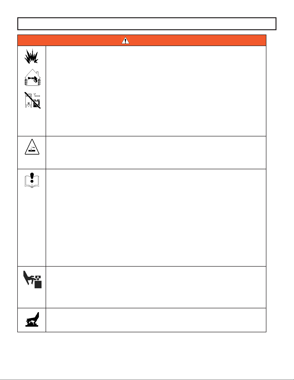
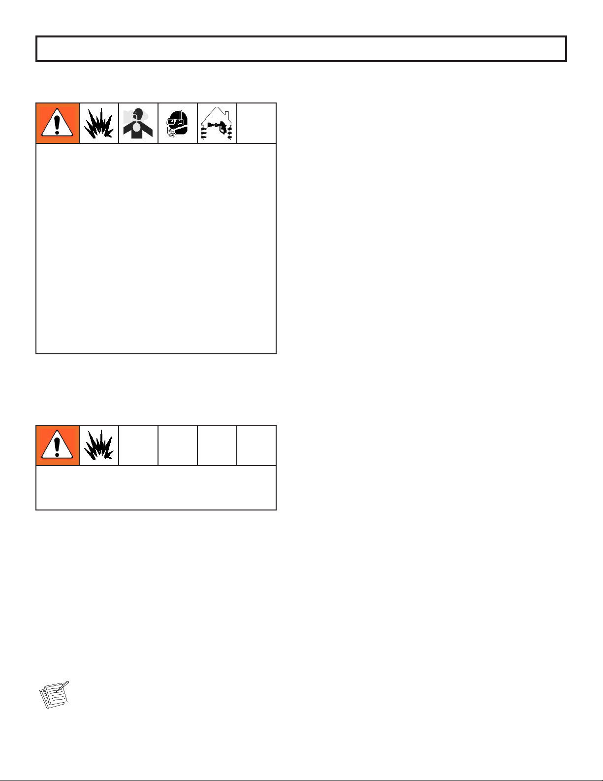
FIRE AND EXPLOSION HAZARD
Flammablefumes,suchassolventandpaintfumes,inworkareacanigniteorexplode.Tohelppre-
ventreandexplosion:
Use equipment only in well ventilated area.•
Eliminate all ignition sources; such as pilot lights, cigarettes, portable electric lamps, and plastic•
drop cloths (potential static arc).
Keepworkareafreeofdebris,includingsolvent,ragsandgasoline.•
Donotplugorunplugpowercords,orturnpowerorlightswitchesonoroffwhenammable•
fumes are present.
Groundallequipmentintheworkarea.•
Use only grounded hoses.•
Holdgunrmlytosideofgroundedpailwhentriggeringintopail.•
Ifthereisstaticsparkingoryoufeelashock,• stop operation immediately. Do not use equip-
ment until you identify and correct the problem.
Keepaworkingreextinguisherintheworkarea.•
PRESSURIZED ALUMINUM PARTS HAZARD
Do not use 1,1,1-trichloroethane, methylene chloride, other halogenated hydrocarbon
solventsoruidscontainingsuchsolventsinpressurizedaluminumequipment.Such
use can cause serious chemical reaction and equipment rupture, and result in death,
seriousinjury,andpropertydamage.
EQUIPMENT MISUSE HAZARD
Misusecancausedeathorseriousinjury.
Donotoperatetheunitwhenfatiguedorundertheinuenceofdrugsoralcohol.•
Donotexceedthemaximumworkingpressureortemperatureratingofthelowestratedsystem•
component. See Technical Data in all equipment manuals.
Useuidsandsolventsthatarecompatiblewithequipmentwettedparts.See• Technical Data in
allequipmentmanuals.Readuidandsolventmanufacturer’swarnings.Forcompleteinforma-
tion about your material, request MSDS forms from distributor or retailer.
Checkequipmentdaily.Repairorreplacewornordamagedpartsimmediatelywithgenuine•
manufacturer’s replacement parts only.
Do not alter or modify equipment.•
Use equipment only for its intended purpose. Call your distributor for information.•
Routehosesandcablesawayfromtrafcareas,sharpedges,movingparts,andhotsurfaces.•
Donotkinkoroverbendhosesorusehosestopullequipment.•
Keepchildrenandanimalsawayfromworkarea.•
Comply with all applicable safety regulations.•
MOVING PARTS HAZARD
Movingpartscanpinchoramputatengersandotherbodyparts.
Keep clear of moving parts.•
Do not operate equipment with protective guards or covers removed.•
Pressurizedequipmentcanstartwithoutwarning.Beforechecking,moving,orservicingequip-•
ment, follow the Pressure Relief Procedure in this manual. Disconnect power or air supply.
BURN HAZARD
Equipmentsurfacesanduidthat’sheatedcanbecomeveryhotduringoperation.Toavoid
severeburns,donottouchhotuidorequipment.Waituntilequipment/uidhascooledcompletely.
Warnings

3
Warnings
Isocyanate Hazard
Spraying materials containing isocyanates creates
potentially harmful mists, vapors, and atomized
particulates.
Read material manufacturer’s warnings and
materialMSDStoknowspecichazardsand
precautions related to isocyanates.
Prevent inhalation of isocyanate mists, vapors, and
atomizedparticulatesbyprovidingsufcientventila-
tionintheworkarea.Ifsufcientventilationisnot
available, a supplied-air respirator is required for
everyoneintheworkarea.
To prevent contact with isocyanates, appropriate
personal protective equipment, including chemically
impermeable gloves, boots, aprons, and goggles, is
alsorequiredforeveryoneintheworkarea.
Material Self-Ignition
Some materials may become self-igniting if applied
toothickly.Readmaterialmanufacturer’swarnings
and material MSDS.
Moisture Sensitivity of
Isocyanates
Isocyanates (ISO) are catalysts used in two component
foam and polyurea coatings. ISO will react with moisture
(such as humidity) to form small, hard, abrasive crystals,
whichbecomesuspendedintheuid.Eventuallyalmwill
form on the surface and the ISO will begin to gel, increas-
ing in viscosity. If used, this partially cured ISO will reduce
performance and the life of all wetted parts.
Theamountoflmformationandrateofcrystal-
lization varies depending on the blend of ISO,
the humidity, and the temperature.
To prevent exposing ISO to moisture:
Always use a sealed container with a desiccant dryer•
in the vent, or a nitrogen atmosphere. Never store ISO
in an open container.
KeeptheISOlubepumpreservoirlledwithGraco•
Throat Seal Liquid (TSL), Part 206995. The lubricant
creates a barrier between the ISO and the atmosphere.
Usemoisture-proofhosesspecicallydesignedfor•
ISO, such as those supplied with your system.
Never use reclaimed solvents, which may contain•
moisture.Alwayskeepsolventcontainersclosedwhen
not in use.
Never use solvent on one side if it has been contami-•
nated from the other side.
Alwaysparkpumpswhenyoushutdown.•
Always lubricate threaded parts with Part 217374 ISO•
pump oil or grease when reassembling.

4
Keep Components A and B
Separate
CAUTION
To prevent cross-contamination of the equipment’s wet-
ted parts, never interchange component A (isocyanate)
and component B (resin) partrs. The gun is shipped with
theAsideontheleft.Theuidmanifold,uidhous-
ing,sidesealassembly,checkvalvecartridge,andmix
chamberaremarkedontheAside.
Foam Resins with 245 fa
Blowing Agents
New foam blowing agents will froth at temperatures above
90°F (33 °C) when not under pressure, especially if agitat-
ed. To reduce frothing, minimize preheating in a circulation
system.
Changing Materials
Whenchangingmaterials,ushtheequipmentmul-•
tiple times to ensure it is thoroughly clean.
Alwayscleantheuidinletstrainersafterushing.•
Checkwithyourmaterialmanufacturerforchemical•
compatibility.
Most materials use ISO on the A side, but some use•
ISO on the B side.
Epoxies often have amines on the B (hardener) side.•
Polyureas often have amines on the B (resin) side.
Warnings

5
Section 1 - Installation: Standard Equipment
Model - A6-6000 IP
Part
Number Description
GC1820 A6-6000 IP UNIT, 220V, 1PH, F
GC1822 A6-6000 IP UNIT, 220V, 3PH, F
GCP2R1* PROBLER P2 GUN
GC0393* 48 FT. HEATED HOSE ASSEMBLY
313274 USER MANUAL
206995 FLUID, TSL, 1 AT. BOTTLE
GC0174 TRANSFER KIT, A5 AND A6
(DOES NOT INCLUDE TRANSFER PUMPS
* Purchased Separately
Part
Number Description
GC1748 HEATER REPAIR KIT
Part
Number Description
312766 T1 2:1 RATIO TRANSFER PUMP MANUAL
313277 MATERIAL PUMPS MANUAL
Recommended Repair Parts
Related Manuals

6
Material Ratio: 1:1 (Fixed)
Material Viscosity: 200- 2000 Centipoise (Cps) @ AMBIENT
Output: Pumps Rated:
.042 Gallons Per Cycle
.159 Liters Per Cycle
Operating Temperatures: 32º F ( 0º C ) - 180º (82 º C )
MaximumAirWorkingPressure: 100psi(0.69MPa,6.9bar)
MaximumFluidWorkingPressure: 22:1RATIO2200psi(15.2MPa,152bar)
ElectricalRequirements: 50A@208/240VAC,50/60hz,SinglePhase
(cable: 6 AWG, 2 wire + GND)
25A@208/240VAC,50/60hz.ThreePhase
(cable: 10 AWG, 3 wire + GND)
Compressed Air Requirements: Base Unit:
1.0 GAL PER MINUTE – 17 CFM @ 100 PSI.
1.5 GAL PER MINUTE – 24 CFM @ 100 PSI.
2.0 GAL PER MINUTE – 33 CFM @ 100 PSI.
NOTE:Asoutputisincreased,(achievedw/chamber
size on gun or spray tip), pressure drop will be greater.
Heating capability will also drop.
Heaters: 6000 WATT HEATER
Maximum Hose Length: 200 ft (61 m)
(EachSection50ft.x1/4in.I.D.)
ShippingWeight: 440lbs.(200kg)
Overall Dimensions:
Section 1 - Installation: Specications

7
Before operating, maintaining or servicing any
GlasCraft system, read and understand all of the
technical and safety literature provided with GlasCraft
products. If you do not have the proper or related
manuals and safety literature for your GlasCraft system,
contact your GlasCraft distributor.
In this GlasCraft technical and safety publication, the
following advisories will be provided where appropriate:
Information about the procedure in progress.
Is imperative information about equipment protection.
Indicates a hazardous situation that can result in minor
or moderate injury.
Indicates a hazardous situation that can result in death
or serious injury.
Indicates a hazardous situation that can result in electr-
ical shock or serious injury.
The information in this document is intended only to
indicatethecomponentsandtheirnormalworking
relationship typical use. Each assembly should be
directed by a GlasCraft distributor or made from the
GlasCraft Assembly instructions provided.
This manual provides information for the assembly, opera-
tion, maintenance and service of this GlasCraft product as
usedinatypicalconguration.Whileitlistsstandardspeci-
cations and procedures, some deviations may be found.
In order to provide our users with the most up-to-date
technologypossible,weareconstantlyseekingtoimprove
products. If a technological change occurs after a prod-
uctisonthemarket,wewillimplementthattechnologyin
futureproductionand,ifpractical,makeitavailabletocur-
rentusersasaretrot,updateorsupplement.Ifyound
a discrepancy between your unit and the available docu-
mentation, contact your GlasCraft distributor to resolve the
difference.
Careful study and continued use of this manual will pro-
vide a better understanding of the equipment and process,
resultinginmoreefcientoperation,longertrouble-free
service and faster, easier troubleshooting.
ELECTRICAL SHOCK HAZARD
WARNING
CAUTION
Section 1 - Installation: Introduction

Section 4 - Safety Information: Notes
8

9
Section 1 - Installation: Equipment Assembly
Guardian Line Installation Guide
GlasCraft Systems are factory assembled. If any
questions arise concerning air or electrical
connections, please refer to illustrations located in
the forward portion of this User Manual or contact
your GlasCraft distributor.
1. Locate Guardian.
a. Locate Guardian on a level surface.
b. Do not expose Guardian to rain.
CAUTION
Bolt Guardian to original shipping palet before lifting.
c. UsethewheelstomoveGuardiantoaxed
location, or bolt to shipping pallet and move
withforklift.
d. Tomountonatruckbedortrailer,boltdirectlyto
truckortrailerbed.
2. Advanced preparation
a. Before beginning any installation, ensure that the
applicator has the desired power supply available,
(i.e.220Vsinglephase/380Vthreephase),
within 10 ft. of were the machine is to be placed.
If the machine needs to be further that 10 ft. from
the power supply, additional lengths of properly
sized electrical cable will be required.
Never use a smaller gauge size than supplied
by the factory!
b. Depending on the electrical setup, it may be
necessary to install an appropriate plug on the end
of the cable. GlasCraft will not supply this plug, as
we are unaware of which style will be needed.
c.Consultthedatasheetforthespecicunitbeing
installedtodeterminetheproperbreakersize
needed.
d. You will need to run an air line to the area where
the machine will be placed. consult the data
sheetthespecicunitbeinginstalledtodetermine
much clean, dry air will be needed to supply the
machine. If the air line is under 25 ft. use a
minimumof1/2in.I.D.pipeorhose.Iftheairline
is longerthan25ft.,useaminimumof3/4in.
pipe or hose. Anything smaller than these
diameters will severly affect the machine’s
performance!
Do not use any quick disconnect ttings on
the main air line going to the machine!
Check your air-compressor to make sure it is
capable of supplying the maximum amount of air
that the machine requires. All GlasCraft equipment
is rated at 25 CFM (cubic foot per minute) 708
liters at 90- 100 psi (.62-0.7 MPa, 6.3-7.7 bar)
do not exceed 125 psi (0.86 MPa, 8.6 bar).
3. Move material drums to the area that the equipment will
be placed, ensuring that they are not sitting directly on
theoor.Simplyplacethedrumsontopofapalateor
similar device, so the drum bottoms will not be in
contact with any cold surfaces.
4. Open all boxes that came with the machine and verify
that all items are accounted for.
5. Install feed pumps (purchased separately) in POLY and
ISO material drums.
6.Installa“y”lter(purchasedseparately)totheoutletof
both pumps.
Be sure to use PTFE tape on the threads.

10
Section 1 - Installation: Equipment Assembly
7. Seal component A drum and use desiccant dryer.
8. See transfer pump manual for setup instructions.
9. Remove the metal caps from the material pumps.
10. Connect one end of each material hose to the inlet
ttingslocatedonthebackofthemachine.It is
highly recommended that you label the (POLY)
hose with BLUE tape and the (ISO) hose with RED
tape to ensure that you don’t put the wrong transfer
pump in the opposite material drum.
POLY
Material
Drum

11
Section 1 - Installation: Equipment Assembly
POLY
Material
Inlet Fitting
ISO
Material
Inlet Fitting
11. Connect the other end of the material hoses to there
correct transfer pumps. Ensure that they are not reversed
and tighten securely.
12. Attach the other end of the airlines to the far right
regulator on the machines air manifold.
ISO
Material
Drum

12
Section 1 - Installation: Equipment Assembly
Main power from power source should be disconnected
orturnedofftoconsolebeforemakinghose
connections.
Trigger Air
13. Connect the hose assembly to the
unit.TheswivelttingsontheHose
assembly are sized differently and will
attach only one way.
14. Connect the “yellow” heat plug to the
outlet on the front of the unit.
15. Connect trigger air line to the air
regulator at the system air manifold.
16. Connect the thermocouple plug
totheoutletonthe“back”oftheunit.

13
Section 1 - Installation: Equipment Assembly
17. Continue adding extra hose lengths if necessary.
The GlasCraft System is factory assembled. If
any questions arise concerning air or electrical
connections, please refer to illustrations located in
the forward portion of this User Manual or contact
your GlasCraft distributor.
Required Tools:
Opened-endwrenches-5/8”,3/4”,13/16”
a. Lay hoses out straight.
b. Couplehosestogetherwithsuppliedunionttings
andtightennger-tight.
c. •Holdcrimpttinghex(3/4”),anduniontting
together, allowing the hose to hold it’s natural line.
•Usingtheappropriatewrench(A-side3/4”/B-side
13/16”)tightenswivelttingtounion,notallowing
crimpttingoruniontoturn.Repeatonopposite
side of union.
This practice is required on all connection
points.
1) Hose @ machine
2) Hose @ gun
3) Adding additional hose sections
d. Attach the yellow power plugs.
e. Attach the thermocouple
extensioncable.p/n21998-00
GC0705 Extension hose
Machine End
Machine End
GC0393 Standard hose
Gun End

14
Section 1 - Installation: Equipment Assembly
18. Connect the hose assembly to the spray gun as
shown.
19. All connections should now be tight!
When Main Power to system console is on, the white
and black wires in the console are always live!
Disconnect or turn off Main Power source before
opening console to make any repairs or before making
any electrical repair of any type to the system.
If you do not understand the electrical hook-up
described above, consult your local GlasCraft distributor
OR a qualied electrician.
Electrical connections must be checked on a
periodic basis.
20. ConnectthewhiteandblackwiresofthePower
cordtoasinglephaseof208/240VAC,50/60HZ.
The green wire should be connected to GROUND
WHITE
GREEN
BLACK
POWER CORD
208 / 240 VAC
50 / 60 HZ.
SINGLE PHASE
25 AMP MIN.
GROUND
50

15
Never leave machine unattended while system power
is on or system is running.
System running is dened as: preheat cycle of the hose
heat, primary heaters, or any pump operation.
Machine operators must be familiar with the
component functions and operation of the machine.
Pre-Operation Check List
A. Checkthatallttingsaresecurelytight.
B. Checkelectricalhook-up(qualiedelectrician
recommended).
C. Main power switch on control box should be
switched to OFF position.
D.Airregulatorturned(counterclock-wise)toOFF
position.
E. Hose control and primary heater control to OFF
position.
Do not place any part of the body in the path of the
material spray.
Do not point the gun at or near other personnel.
Do not look into the mixing chamber orice at any time.
Because of the hazardous materials used in this
equipment, it is recommended that the operator use
an air mask, goggles, protective clothing, and other
safety equipment as prescribed by current regulations,
recommendations of the chemical suppliers, and the
laws in the area where the equipment is being used.
Initial Start-Up Procedure
With all material and air lines connected and power
cable attached, the system is now ready for start-up.
Filling The System
1. Adjustairregulatorto20psitollsystem.Air
motorwillcycleslowlytollpumps,heatersand
hoses and stop.
2. RemoveISO&POLYsideblocksfromgun.
PROBLER P2
MAKE SURE VALVES ARE OFF
Section 2 - Operation: Start-Up Instructions

16
3. Place separate clean containers under each indi-
vidualsideblock.Slowly open material valves
(blackarrowforward)oneachsideblocktoallow
trappedairtoescapethehoseandmaterialtoow
into the containers until all air is purged from the
material system.
Remember to dispense one to two gallons of
material to clear the system of grease and
plasticizer that was used during factory testing.
4. Close manual material valves. Material pressure
gauges should now register approximately equal
pressure. If one side registers considerably more
pressure than the other side, go to the high pres-
sure side and bleed off some pressure by slightly
opening the manual material valve on the side
blockoverthecontainer.Bleedpressureuntilboth
sides are approximately the same pressure.
5. Dispose of waste material properly and in accor-
dance with chemical suppliers instructions and
local, state and federal regulations.
Before re-assembling side blocks, lubrication can be
applied by dabbing a white lithium grease into
holes inside of gun front housing and wiping
grease over side block seals. Grease will purge
itself when air valve is turned on at gun and gun
is triggered.
6.Cleanandlubricatesideblocksandsealsthoroughly
andre-assembleongun.Makecertainthattheside
blockscrewsaretightenedsecurely.
7. Refer to material manufacturers operating instructions
for proper preparation of material, i.e, mixers, etc.
8. Leave air regulator at 20 psi.
9. Turn main power switch to ON position.
10. Turn on Hose Control:
a. Push in the green power button.
b. Press up or down arrow buttons on the controller
until desired temperature setting is achieved.
Section 2 - Operation: Start-Up Instructions

17
11. Turn on the ISO & POLY heater control:
a. Push in green power button.
b. Press up or down arrow buttons on the
controller until desired temperature setting is
achieved.
Straighten hose out at, to avoid uneven heating and
damage to internal wiring of the Hose Assembly.
Allow enough time for hose to warm up (approximately
15- 20 minutes). Remember that the heated hose
does not have a delta rating. The heated hose’s func-
tion is to maintain the heat generated by the primary
heaters during system operation, and preheat material
during initial start-up. The hose should be set to
maintain a temperature close to the set point of the
heaters.
Due to the expansion of urethanes when heated, it is
imperative that on cold start-up of the system that the
heaters be turned on and allowed to reach operating
temperatures before the main pump air regulator is
adjusted to the desired spray pressure. If you do not
allow the heaters to reach operating temperature before
adjusting air pressure, the material pressure will exceed
the set point of the over pressure switches causing the
system to shut down.
12.Adjustmainairregulatortomaterialsuppliers
specications.
13. Turn purge air and material valves ON at gun.
ON OFF
14. Relieve any excess pressure by triggering the gun.
The emergency stop switch is located on the bottom
right side of the control panel, when depressed, it will
shut down the power and activate the air dump valve.
To reset, turn handle on push button.
15. The system is now ready for operation.
Section 2 - Operation: Start-Up Instructions

Change Temperature Controller Display
Units (Fhrenheit or Celsius)
220 V units are factory set to display temperature readings
in degrees Fahrenheit. 380 V units are factory set to display
tempertature readings in degrees Celsius.
The temperature display units can be changed with the fol-
lowing procedure:
1. On the Watlow SD31 controller, press and hold
the and buttons simultaneously for 3
seconds until the display reads “SET”. This is the
Setup Menu.
2. Scroll through the Setup Menu by pressing the .
button until the display reads “C-F” (press button
3 times).
3. Press and hold the button to display the current
unit setting of “C” of “F”.
4. Continue to hold the button and press the
button to switch to the desired unit setting, “C” or “F”.
5. Release the button.
6. Press the button to exit the Setup Menu; the
temperature display unit is now changed.
7. Complete steps 1-6 for all three controllers (ISO, POLY,
HOSE).
Do not change any other settings in the Setup Menu.
The settings have been factory programmed for opti-
mal performance.
Section 2 - Operation: Start-Up Instructions
18
Table of contents
Other Glas Craft Dispenser manuals

Glas Craft
Glas Craft MH II User manual

Glas Craft
Glas Craft Auto Probler P2 User manual

Glas Craft
Glas Craft Probler User manual

Glas Craft
Glas Craft Probler P2 User manual

Glas Craft
Glas Craft GUARDIAN User manual

Glas Craft
Glas Craft GCP3RA User manual

Glas Craft
Glas Craft MH II User manual

Glas Craft
Glas Craft GUARDIAN A5-3000 IP User manual

Glas Craft
Glas Craft Guardian A5-6000 IP User manual
Popular Dispenser manuals by other brands

Borg & Overstrom
Borg & Overstrom u2 40L user guide

Georgia Pacific
Georgia Pacific enMotion 52057KB reference guide

Sanela
Sanela SLZN 74 instruction manual

Marco
Marco MIX Font instruction manual

Hydro
Hydro AccuDose 3874AG-2 Installation and operation

Wilbur Curtis
Wilbur Curtis Primo Cappuccino PCGT3 user guide