manuals.online logo
Brands
  1. Home
  2. •
  3. Brands
  4. •
  5. Mayr
  6. •
  7. Industrial Equipment
  8. •
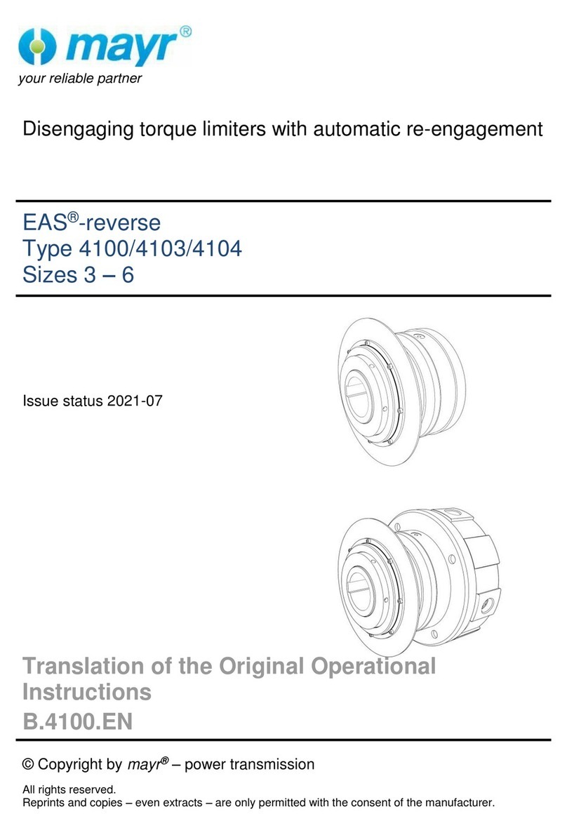
  9. Mayr ROBA-takt Quick start guide

Mayr ROBA-takt Quick start guide

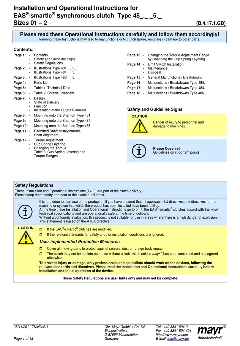
Installation and Operational Instructions for
ROBA®-takt clutch brake unit with 'energise to engage' brake
Type 67_.0_ _._ Sizes 3 to 7 (B.6.1.EN)
21/06/2018 GC/SI/EI/SU Chr. Mayr GmbH + Co. KG
Eichenstraße 1, D-87665 Mauerstetten, Germany
Tel.: +49 8341 804-0, Fax: +49 8341 804-421
Page 1 of 7 www.mayr.com, E-Mail: info@mayr.com
Please read these Operational Instructions carefully and follow them accordingly!
Ignoring these instructions may lead to malfunctions or to failure of the clutch brake unit, resulting in damage to other parts.
These Installation and Operational Instructions (I + O) are part of the delivery.
Please keep them handy and near to the clutch brake unit at all times.
Contents
Page 1: - Contents
- Safety and Guideline Signs
- Guidelines on EU Directives
Page 2: - Safety Regulations
Page 3: - Safety Regulations
Page 4: - Safety Regulations
Page 5: - Clutch Brake Unit Illustration
- Parts List
- Design
- Function
- Ambient Conditions
- Torque
Page 6: - Electrical Connection
- Installation
Page 7: - Permitted Shaft Load
- Disposal
Safety and Guideline Signs
DANGER
Immediate and impending danger, which can
lead to severe physical injuries or to death.
CAUTION
Danger of injury to personnel and damage to
machines.
Please Observe!
Guidelines on important points.
Guidelines on the Declaration of Conformity
A conformity evaluation has been carried out for the product (electromagnetic clutch brake unit) in terms of the EU Low
Voltage Directive 2014/35/EU. The Declaration of Conformity is laid out in writing in a separate document and can be
requested if required.
Guidelines on the EMC Directive (2014/30/EU)
The product cannot be operated independently according to the EMC directive.
Due to their passive state, brakes and clutches are also non-critical equipment according to the EMC. Only after
integration of the product into an overall system can this be evaluated in terms of the EMC.
For electronic equipment, the evaluation has been verified for the individual product in laboratory conditions, but not in the
overall system.
Guidelines on the Machinery Directive (2006/42/EC)
The product is a component for installation into machines according to the Machinery Directive 2006/42/EC.
The product can fulfil the specifications for safety-related applications in coordination with other elements.
The type and scope of the required measures result from the machine risk analysis. The product then becomes a machine
component and the machine manufacturer assesses the conformity of the safety device to the directive.
It is forbidden to start use of the product until you have ensured that the machine accords with the regulations stated in the
directive.
Guidelines on the EU Directive on the Restriction of the Use of Certain Hazardous Substances in Electrical and
Electronic Equipment
The product as well as the rectifiers / microswitches / proximity switches required for control / self-monitoring fulfil the
requirements laid down in the EU Directive 2011/65/EU (RoHS) (restrictions on the use of certain hazardous substances,
such as lead (0.1 %), mercury (0.1 %), cadmium (0.01 %), hexavelent chromium (0.1 %), polybrominated biphenyls (PBB)
(0.1 %), polybrominated diphenylethers (PBDE) (0.1 %)). In addition, the substances listed in the delegated Directive
2015/863 EU –22 July 2019, Di(2-ethylhexyl)phthalate (DEHP) (0.1 %), butylbenzylphthalate (BBP) (0.1 %),
dibutylphthalate (DBP) (0.1 %) and diisobutylphthalate (DIBP) (0.1 %) are also not included.
Guidelines on the ATEX Directive
Without a conformity evaluation, this product is not suitable for use in areas where there is a high danger of explosion.
For application of this product in areas where there is a high danger of explosion, it must be classified and marked
according to Directive 2014/34/EU.
Installation and Operational Instructions for
ROBA®-takt clutch brake unit with 'energise to engage' brake
Type 67_.0_ _._ Sizes 3 to 7 (B.6.1.EN)
21/06/2018 GC/SI/EI/SU Chr. Mayr GmbH + Co. KG
Eichenstraße 1, D-87665 Mauerstetten, Germany
Tel.: +49 8341 804-0, Fax: +49 8341 804-421
Page 2 of 7 www.mayr.com, E-Mail: info@mayr.com
Safety Regulations
These Safety Regulations are user hints only and may not be complete!
General Guidelines
DANGER
Danger of death!
Do not touch voltage-carrying lines and
components.
Clutches may generate further risks, among other things:
Hand injuries
Danger of
seizure
Contact with
hot surfaces
Magnetic
fields
Severe injury to people and damage to objects may result if:
the clutch brake unit is used incorrectly.
the clutch brake unit is modified.
the relevant standards for safety and / or installation
conditions are ignored.
During the risk assessment required when designing the
machine or system, the dangers involved must be evaluated and
removed by taking appropriate protective measures.
To prevent injury or damage, only specialist personnel are
allowed to work on the components.
They must be familiar with the dimensioning, transport,
installation, inspection of the clutch equipment, initial operation,
maintenance and disposal according to the relevant standards
and regulations.
Before product installation and initial operation,
please read the Installation and Operational
Instructions carefully and observe the Safety
Regulations. Incorrect operation can cause injury
or damage. At the time these Installation and
Operational Instructions go to print, the clutch brake units
accord with the known technical specifications and are
operationally safe at the time of delivery.
Technical data and specifications (Type tags and
documentation) must be followed.
The correct connection voltage must be connected
according to the Type tag and wiring guidelines.
Check electrical components for signs of damage before
putting them into operation. Never bring them into contact
with water or other fluids.
Please observe the EN 60204-1 requirements for electrical
connection when using in machines.
Only carry out installation, maintenance and
repairs in a de-energised, disengaged state
and secure the system against inadvertent
switch-on.
Guidelines for Electromagnetic Compatibility
(EMC)
In accordance with the EMC directives 2014/30/EU, the
individual components produce no emissions. However,
functional components e.g. mains-side energisation of the clutch
brake units with rectifiers, phase demodulators, ROBA®-switch
devices, ROBA®-takt control units, ROBA®-takt circuit modules or
similar controls can produce disturbance which lies above the
allowed limit values. For this reason it is important to read the
Installation and Operational Instructions very carefully and to
keep to the EMC directives.
Application Conditions
The catalogue values are guideline values which
have been determined in test facilities. It may be
necessary to carry out your own tests for the
intended application. When dimensioning the
clutch brake units, please remember that
installation situations, braking torque fluctuations, permitted
friction work, bedding-in condition / conditioning of the brake
linings and wear as well as general ambient conditions can all
affect the given values. These factors should therefore be
carefully assessed, and alignments made accordingly.
Mounting dimensions and connection dimensions must be
adjusted according to the size of the clutch brake unit at the
place of installation.
The clutch brake units are designed for a relative duty cycle
of 100%.
The braking torque is dependent on the current bedding-in
condition of the brake. Bedding in / conditioning of the
friction linings is necessary.
The clutch brake units are only designed for dry running. The
torque is lost if the friction surfaces come into contact with
oil, grease, water or similar substances or any other foreign
bodies.
CAUTION
The friction surfaces may rust up and seize up
in corrosive ambient conditions and / or after
longer downtimes.
The user is responsible for taking appropriate
countermeasures.
Installation and Operational Instructions for
ROBA®-takt clutch brake unit with 'energise to engage' brake
Type 67_.0_ _._ Sizes 3 to 7 (B.6.1.EN)
21/06/2018 GC/SI/EI/SU Chr. Mayr GmbH + Co. KG
Eichenstraße 1, D-87665 Mauerstetten, Germany
Tel.: +49 8341 804-0, Fax: +49 8341 804-421
Page 3 of 7 www.mayr.com, E-Mail: info@mayr.com
Safety Regulations
These Safety Regulations are user hints only and may not be complete!
Climate Conditions
The ROBA®-takt clutch brake unit is suitable for applications with
an ambient temperature of between -20 °C and +40 °C.
CAUTION
Reduction in torque possible
Condensation can form on the friction surfaces
and cause a loss in torque:
due to fast changes in temperature
at temperatures of around or under
freezing point
The user is responsible for taking appropriate
countermeasures (e.g. forced convection,
heating, drain screw).
CAUTION
Malfunction of ROBA®-takt clutch brake unit
possible
Condensation can form on the friction surfaces
and cause malfunctions:
at temperatures around or under freezing
point, the clutch brake unit can freeze over
and not disengage any more.
The user is responsible for taking appropriate
countermeasures (e.g. forced convection,
heating, drain screw).
Intended Use
mayr®-clutch brake units have been developed, manufactured
and tested in compliance with the DIN VDE 0580 standard and in
accordance with the EU Low Voltage Directive as electromagnetic
components. During installation, operation and maintenance of the
product, the requirements for the standard must be observed.
mayr®-clutch brake units are for use in machines and systems
and must only be used in the situations for which they are ordered
and confirmed. Using them for any other purpose is not allowed.
Earthing Connection
The clutch brake unit is designed for Protection Class I. This
protection covers not only the basic insulation, but also the
connection of all conductive parts to the protective conductor (PE)
on the fixed installation. If the basic insulation fails, no contact
voltage will remain. Please carry out a standardised inspection of
the protective conductor connections to all contactable metal
parts!
Class of Insulation F (+155 °C)
The insulation components on the magnetic coils are
manufactured at least to class of insulation F (+155 °C).
Protection IP55
Dust-proof and protected against contact as well as against jet
water from a nozzle coming from any direction.
Storage of ROBA®-takt clutch brake units
Store the clutch brake units in a horizontal position, in dry
rooms, dust and vibration-free.
Relative air humidity < 50 %.
Temperature without major fluctuations within a range from
-20 °C up to +40 °C.
Do not store in direct sunlight or UV light.
Do not store aggressive, corrosive substances (solvents /
acids / lyes / salts / oils / etc.) near to the brakes.
For longer storage of more than 2 years, special measures are
required (please contact the manufacturer).
Storage acc. DIN EN 60721-3-1 (including the limitations /
additions described above): 1K3; 1Z1; 1B1; 1C2; 1S3; 1M1
Handling
Before installation, the clutch brake unit must be inspected and
found to be in proper condition.
The clutch brake unit function must be inspected both once
attachment has taken place as well as after longer system
downtimes, in order to prevent the drive starting up against
possibly seized friction surfaces.
User-implemented Protective Measures:
Please cover moving parts to protect against injury
through seizure.
Attach a cover to protect against injury through high
temperatures on the housing
Protection circuit: When using DC-side switching, the coils
must be protected by a suitable protection circuit according
to VDE 0580, which is integrated in mayr®-rectifiers. To
protect the switching contact from consumption when using
DC-side switching, additional protective measures are
necessary (e.g. series connection of switching contacts).
The switching contacts used should have a minimum contact
opening of 3 mm and should be suitable for inductive load
switching. Please make sure on selection that the rated
voltage and the rated operating current are sufficient.
Depending on the application, the switching contact can also
be protected by other protection circuits (e.g. mayr ®-spark
quenching unit, half-wave and bridge rectifiers), although this
may of course then alter the switching times.
Install additional protective measures against corrosion if
the clutch brake unit is subject to extreme ambient
conditions or is installed in open air conditions, unprotected
from the weather.
Take precautions against freeze-up of the friction
surfaces in high humidity and at low temperatures.
Installation and Operational Instructions for
ROBA®-takt clutch brake unit with 'energise to engage' brake
Type 67_.0_ _._ Sizes 3 to 7 (B.6.1.EN)
21/06/2018 GC/SI/EI/SU Chr. Mayr GmbH + Co. KG
Eichenstraße 1, D-87665 Mauerstetten, Germany
Tel.: +49 8341 804-0, Fax: +49 8341 804-421
Page 4 of 7 www.mayr.com, E-Mail: info@mayr.com
www.mayr.com
Made in
Germany
+49-8341/804-0
ROBA -RT
®7000000
KU ??V/??W
BR ??V/??W
S0000000
Safety Regulations
These Safety Regulations are user hints only and may not be complete!
Standards, Directives and Regulations
Used and To Be Applied
DIN VDE 0580 Electromagnetic devices and
components, general specifications
2014/35/EU Low Voltage Directive
CSA C22.2 No. 14-2010 Industrial Control Equipment
UL 508 (Edition 17) Industrial Control Equipment
EN ISO 12100 Safety of machinery –General
principles for design - Risk assessment
and risk reduction
DIN EN 61000-6-4 Interference emission
DIN EN 61000-6-2 Interference immunity
Liability
The information, guidelines and technical data in these
documents were up to date at the time of printing. Demands on
previously delivered brakes are not valid.
Liability for damage and operational malfunctions will not be
taken if:
- the Installation and Operational Instructions are ignored or
neglected.
- the clutch brake units are used inappropriately.
- the clutch brake units are modified.
- the clutch brake units are worked on unprofessionally.
- the clutch brake units are handled or operated incorrectly.
Guarantee
The guarantee conditions correspond with
the Chr. Mayr GmbH + Co. KG sales and delivery
conditions.
Mistakes or deficiencies are to be reported to mayr®at
once!
CE Identification
according to the
Low Voltage Directive 2014/35/EU
Identification
mayr®components are clearly marked and described on the Type tag:
Product name Size/Type Article number
DataMatrix-Code
Serial number
Clutch side:
Voltage / Power
Brake side:
Voltage / Power
CE marking (only for voltages > 72V)
Installation and Operational Instructions for
ROBA®-takt clutch brake unit with 'energise to engage' brake
Type 67_.0_ _._ Sizes 3 to 7 (B.6.1.EN)
21/06/2018 GC/SI/EI/SU Chr. Mayr GmbH + Co. KG
Eichenstraße 1, D-87665 Mauerstetten, Germany
Tel.: +49 8341 804-0, Fax: +49 8341 804-421
Page 5 of 7 www.mayr.com, E-Mail: [email protected]
Fig. 1
Parts List (Only use mayr® original parts)
Item
Name
1
Housing, drive
2
Drive shaft
3
Coil carrier, clutch
4
Automatic re-adjustment
5
Cap screw
6
Deep groove ball bearing
7
Shim rings
8
Locking ring
9
Cap screw
10
Guideline sign, drive
11
Housing, output
12
Output shaft
13
Coil carrier, brake
14
Deep groove ball bearing
15
Radial shaft sealing ring (acc. design)
16
Cap screw
17
Key
18
Guideline sign, output
Design
The ROBA®-takt clutch brake unit consists of an 'energise to
engage' clutch and an 'energise to engage' brake. The electrical
connection is produced via a terminal box with a 4-pole terminal.
The clutch brake unit is completely enclosed and complies with
Protection IP55, the dimensions of the flanges and shafts
correspond to the IEC dimensions.
Due to the patented principle of automatic re-adjustment, the
ROBA®-takt clutch brake unit is maintenance-free for the entire
service lifetime of the clutch and brake.
The clutch brake units are delivered manufacturer-assembled
and set ready for installation.
Function
On continuously running drive machines, the output is coupled
and braked alternately.
Coupling:
The magnetic coil in the clutch is energised, the magnetic coil in
the brake must be voltage-free.
The rotating drive shaft (2) attracts the armature disk. The torque
is transmitted via frictional locking from the drive shaft (2) via the
armature disk onto the output shaft (12).
Braking:
The brake coil is energised, the clutch coil must be voltage-free.
The armature disk is attracted by the fixed brake coil carrier (13).
The output shaft (12), which is connected with the armature disk
via disks, is braked.
The drive shaft (2) runs continuously.
Ambient Conditions
ROBA®-takt clutch brake units are designed for dry running.
Ambient temperature: -20 °C up to +40 °C
CAUTION
At temperatures of around or under freezing
point (ambient temperatures of -20 °C up to
+5 °C), both condensation and the special
characteristics of the linings (lower friction
values at lower temperatures) can strongly
reduce the torque. During longer downtimes,
the friction linings can stick to the friction
surfaces. The user is responsible for taking
appropriate countermeasures.
An ambient temperature of +40 °C should not be exceeded if the
device is run with friction work values in the area of the max.
permitted values.
CAUTION
Higher temperatures lead to unpermittedly
strong heat-up with friction work values in the
limit area.
Torque
The torque (catalogue value) is not achieved until after the run-in
procedure has been carried out.
Normally, this requires approx. 100 switching actions in dynamic
operation. In new condition, approx. 50 % of the torque (M2)
stated in the catalogue is transmitted. Clutch brake units in static
or virtually static operation (i.e. low friction work) do not transmit
the full torque (M2) stated in the catalogue.
Installation and Operational Instructions for
ROBA®-takt clutch brake unit with 'energise to engage' brake
Type 67_.0_ _._ Sizes 3 to 7 (B.6.1.EN)
21/06/2018 GC/SI/EI/SU Chr. Mayr GmbH + Co. KG
Eichenstraße 1, D-87665 Mauerstetten, Germany
Tel.: +49 8341 804-0, Fax: +49 8341 804-421
Page 6 of 7 www.mayr.com, E-Mail: [email protected]
Electrical Connection
The electrical connection of the clutch and brake coil is produced
in the standard series via a 4-pole terminal, which is installed in
the terminal box.
When wiring the clutch brake unit, please make sure that the
clutch and brake are not energised at the same time.
Both coils can be energised either directly via a present source
of DC voltage while observing the required slope separation,
or by using a ROBA®-takt control unit or ROBA®-takt circuit
module.
The ROBA®-takt control unit and the ROBA®-takt circuit module
are supply and control devices for quick switching of the clutch
and brake coil:
The ROBA®-takt control unit is mains connection-side (230
VAC) and offers adjustable slope separation between the
clutch and the brake as well the possibility to switch the 24V
coils quickly via overexcitation.
The ROBA®-takt circuit module does not have an
overexcitation function and requires a coil voltage of 24 VDC
supply-side.
Both Wiring Diagrams and Installation and Operational
Instructions are part of the device delivery.
Brake
Clutch
Slope separation Slope separation
Clutch Brake
Diagram 1
The slope separation avoids simultaneous
occurrence of clutch and braking torques.
Table 1
ROBA®-takt Size
3
4
5
6
7
Slope separation
with overexcitation [ms]
29
33
43
65
106
Slope separation
without
overexcitation [ms]
22
28
37
52
95
When electromagnetic devices are switched off, cut-off peaks
may occur. These can lead to destruction of the device and must
therefore be damped. The damping can have a negative effect
on the switching times stated in the catalogue. Ensure that the
voltage supply is fused acc. the current values.
Installation
Clutch brake unit with flange:
The shafts, centerings, screw-on pitch circles and flange
diameters are produced acc. IEC standard.
The drive and output sides can be screwed together with the
respective flanges of the motor, the gearbox or other clutch
brake units without any problems, see Fig. 2.
Fig.2
Installation of the drive elements:
The drive elements are mounted onto the respective shafts and
secured axially via a press cover and a screw screwed into the
threaded centre hole of the shaft, see Fig. 3.
For the combination motor shaft - ROBA®-takt hollow shaft, the
motor shaft must be greased slightly to prevent fretting corrosion
(copper paste is recommended).
Pressing the drive elements or mounting via hammer blows are
not permitted, as the shaft bearings might be damaged.
Radial loads acting on the shaft via the drive elements must not
exceed the permitted values (see chapter “Permitted Shaft
Load”).
Should both radial and axial loads be present on the shaft, the
permissible loads must be determined (please contact the
manufacturers).
Fig. 3
Installation and Operational Instructions for
ROBA®-takt clutch brake unit with 'energise to engage' brake
Type 67_.0_ _._ Sizes 3 to 7 (B.6.1.EN)
21/06/2018 GC/SI/EI/SU Chr. Mayr GmbH + Co. KG
Eichenstraße 1, D-87665 Mauerstetten, Germany
Tel.: +49 8341 804-0, Fax: +49 8341 804-421
Page 7 of 7 www.mayr.com, E-Mail: [email protected]
Permitted Shaft Load
Fig. 4
The drive elements located on the shafts exert a radial load
during operation which has to be absorbed by the bearings of
the clutch brake unit.
The force value is limited by the required bearing service lifetime
and by the shaft strength (Table 2).
For determining the permitted radial force, the force application
is assumed to apply in the centre of the shaft. If additional axial
forces occur, extensive calculation is necessary (please contact
the manufacturers).
The permitted radial forces stated in Table 3 refer to a speed of
n = 1500 rpm and a bearing service lifetime Lh= 10000 hours.
For different speed or bearing service lifetime values, the
permitted force F can be calculated using the factor k.
The factor k can be determined using Diagram 2.
F = k x FNFmax [N]
F [N]= Permitted radial force
k [-] = Correction factor
Diagram 2
FN[N]= Permitted radial force
with speed n = 1500 rpm and
bearing service lifetime
Lh= 10000 hours
Table 3
Fmax [N]= Max. permitted radial force,
limited due to shaft strength
Table 2
Diagram 2
Table 2: Max. permitted radial force Fmax limited due to the
strength of the shaft, force application in the shaft
centre
ROBA®-takt Size
3
4
5
6
7
Radial force
FN[N]
Drive shaft
without IEC-flange
436
547
681
819
1149
Output shaft
without IEC-flange
788
1052
1484
1685
2861
Output shaft
small IEC-flange
840
1134
1586
1785
3115
Output shaft
large IEC-flange
788
1052
1484
1685
2861
Table 3: Permitted radial force FN with
speed n = 1500 rpm,
bearing service lifetime Lh= 10000 hours
and force application in the shaft centre
ROBA®-takt Size
3
4
5
6
7
Max. permitted
radial force Fmax [N]
Drive shaft
without IEC-flange
333
995
2150
2705
5355
Output shaft
without IEC-flange
333
1105
2331
2950
6211
Output shaft
small IEC-flange
-
-
-
-
-
Output shaft
large IEC-flange
333
1105
2331
2950
6211
Disposal
Our clutch brake unit components must be disposed of
separately as they consist of different materials. Please also
observe the relevant authority regulations. Code numbers may
vary according to the disassembling process
(metal, plastic and cables).
Electronic Components
(Rectifier/ ROBA®-switch):
Products which have not been disassembled can be disposed of
under Code No. 160214 (mixed materials) or components under
Code No. 160216, or can be disposed of by a certified disposal
firm.
Coil carriers (steel pads with coil/cable) and all other steel
components:
Steel scrap (Code No. 160117)
All aluminium components:
Non-ferrous metals (Code No. 160118)
Brake and clutch rotors (steel or aluminium pads with
friction linings):
Brake linings (Code No. 160112)
Seals, O-rings, V-seals, elastomers:
Plastic (Code No. 160119)
Output Drive
Correction factor k [-]
Bearing
service lifetime
LH[h]
Speed [rpm]

Other Mayr Industrial Equipment manuals

Mayr Smartflex 932.3 3 Series Quick start guide

Mayr

Mayr Smartflex 932.3 3 Series Quick start guide

Mayr ROBA-ES 940 Series Quick start guide

Mayr

Mayr ROBA-ES 940 Series Quick start guide

Mayr ROBA-DS 956 Series Quick start guide

Mayr

Mayr ROBA-DS 956 Series Quick start guide

Mayr ROBATIC-clutch Quick start guide

Mayr

Mayr ROBATIC-clutch Quick start guide

Mayr ROBA -brake-checker plus User manual

Mayr

Mayr ROBA -brake-checker plus User manual

Mayr ROBA-servostop 8982.00 01 Quick start guide

Mayr

Mayr ROBA-servostop 8982.00 01 Quick start guide

Mayr ROBA-quick Quick start guide

Mayr

Mayr ROBA-quick Quick start guide

Mayr EAS-Compact 49 Series Quick start guide

Mayr

Mayr EAS-Compact 49 Series Quick start guide

Mayr EAS-dutytorque 404 400 Series Quick start guide

Mayr

Mayr EAS-dutytorque 404 400 Series Quick start guide

Mayr ROBA-stop 820.61 Series Quick start guide

Mayr

Mayr ROBA-stop 820.61 Series Quick start guide

Mayr EAS-Compact-R User manual

Mayr

Mayr EAS-Compact-R User manual

Mayr EAS-NC Quick start guide

Mayr

Mayr EAS-NC Quick start guide

Mayr EAS 400 04.7 Series User manual

Mayr

Mayr EAS 400 04.7 Series User manual

Mayr ROBA-stop-stage Owner's manual

Mayr

Mayr ROBA-stop-stage Owner's manual

Mayr EAS-Compact 49 Series Quick start guide

Mayr

Mayr EAS-Compact 49 Series Quick start guide

Mayr ROBA-stop-S 856 Quick start guide

Mayr

Mayr ROBA-stop-S 856 Quick start guide

Mayr EAS-Sm User manual

Mayr

Mayr EAS-Sm User manual

Mayr ROBA-stop-S Quick start guide

Mayr

Mayr ROBA-stop-S Quick start guide

Mayr EAS-HTL 4190. 5400 Series Quick start guide

Mayr

Mayr EAS-HTL 4190. 5400 Series Quick start guide

Mayr EAS-smartic 484.XX5 Series Quick start guide

Mayr

Mayr EAS-smartic 484.XX5 Series Quick start guide

Mayr ROBATIC 540.1 User manual

Mayr

Mayr ROBATIC 540.1 User manual

Mayr EAS-compact 493. 4 .0 Series User manual

Mayr

Mayr EAS-compact 493. 4 .0 Series User manual

Mayr EAS-HT 405 Series Quick start guide

Mayr

Mayr EAS-HT 405 Series Quick start guide

Mayr ROBA-spot-M 891 Series Quick start guide

Mayr

Mayr ROBA-spot-M 891 Series Quick start guide

Popular Industrial Equipment manuals by other brands

ECOSTAR ECO 1.0 Installation, operating and maintenance manual

ECOSTAR

ECOSTAR ECO 1.0 Installation, operating and maintenance manual

Powerplus POWX902 manual

Powerplus

Powerplus POWX902 manual

Metalworks CAT410 manual

Metalworks

Metalworks CAT410 manual

Delta 32-325 instruction manual

Delta

Delta 32-325 instruction manual

HunterDouglas Luxalon 84B installation instructions

HunterDouglas

HunterDouglas Luxalon 84B installation instructions

TAN Bead Maelstrom 4810 user manual

TAN Bead

TAN Bead Maelstrom 4810 user manual

Alfalaval LeviMag instruction manual

Alfalaval

Alfalaval LeviMag instruction manual

woodmizer LS LT60 Safety, Operation, Maintenance & Parts Manual

woodmizer

woodmizer LS LT60 Safety, Operation, Maintenance & Parts Manual

woodmizer BMT 150-1 Safety, Operation, Maintenance & Parts Manual

woodmizer

woodmizer BMT 150-1 Safety, Operation, Maintenance & Parts Manual

C.R. Laurence CRL 290 Series Assembly instructions

C.R. Laurence

C.R. Laurence CRL 290 Series Assembly instructions

Eaton MMX-NET-XB Instruction leaflet

Eaton

Eaton MMX-NET-XB Instruction leaflet

COMPTROL 36 instruction manual

COMPTROL

COMPTROL 36 instruction manual

ABB HT846171 Operation manual

ABB

ABB HT846171 Operation manual

Seifert 755501B001 user manual

Seifert

Seifert 755501B001 user manual

RSP S20 Installation and Maintenance

RSP

RSP S20 Installation and Maintenance

Car-O-Liner D20 instruction manual

Car-O-Liner

Car-O-Liner D20 instruction manual

Klutch 407116 owner's manual

Klutch

Klutch 407116 owner's manual

ABB HT609424 Operation manual

ABB

ABB HT609424 Operation manual

manuals.online logo
manuals.online logoBrands
  • About & Mission
  • Contact us
  • Privacy Policy
  • Terms and Conditions

Copyright 2025 Manuals.Online. All Rights Reserved.