manuals.online logo
Brands
  1. Home
  2. •
  3. Brands
  4. •
  5. Globe
  6. •
  7. Irrigation System
  8. •
  9. Globe GL-QR Series User manual

Globe GL-QR Series User manual

MAR 2020 GFS-210 PAGE 1 of 3
SERIES GL-QR/INCH/ECLH
EXTENDED COVERAGE, QUICK RESPONSE, LIGHT HAZARD
CONCEALED PENDENT SPRINKLERS
K-FACTOR: 5.6
4077 Airpark Dr. Standish, MI 48658 • 989-846-4583 • www.globesprinkler.com
Technical Support •989-414-2600 •techservice@globesprinkler.com
Note:
Users should refer to Globe’s web site (www.globesprinkler.com)
to assure that the most recent technical literature is being utilized.
GENERAL DESCRIPTION
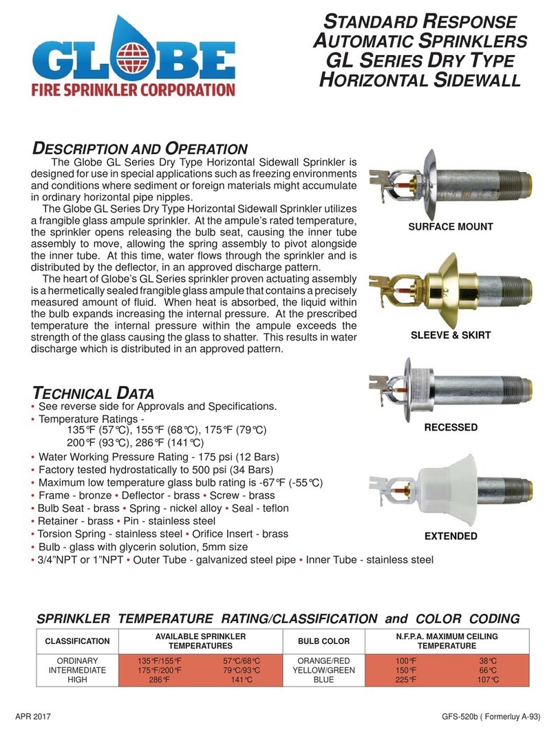
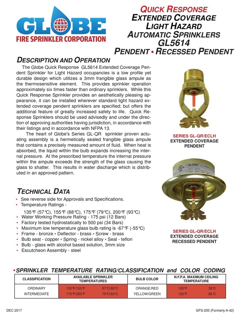
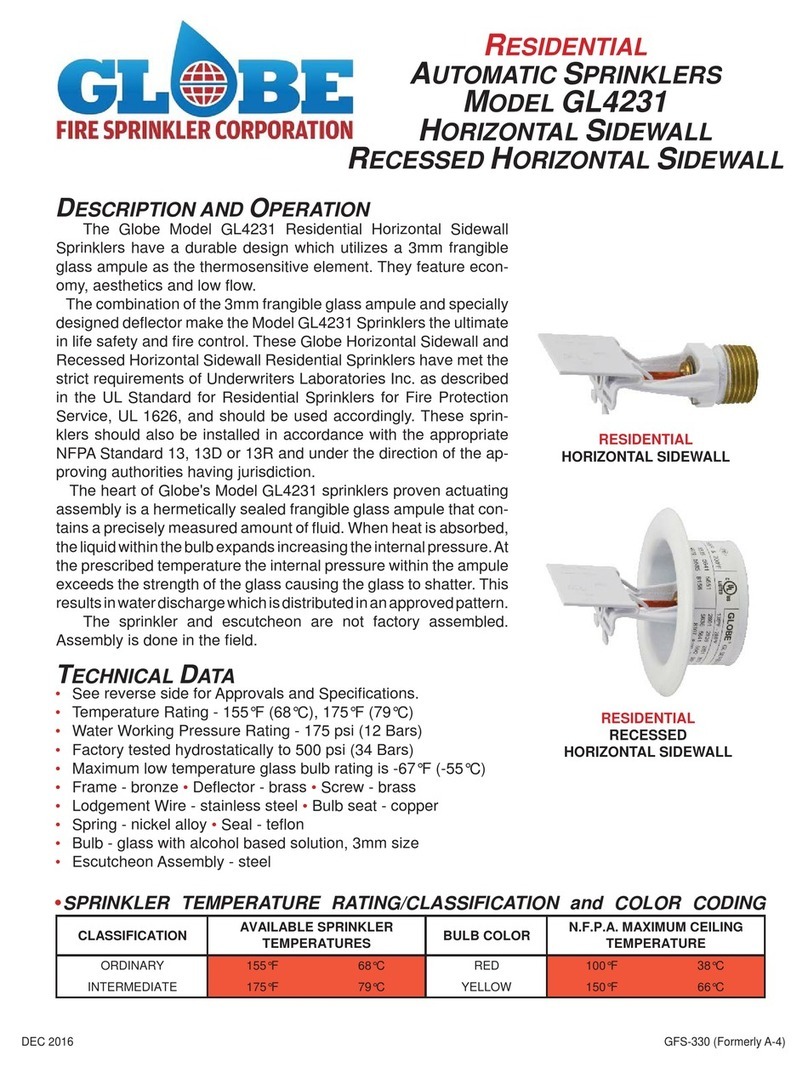
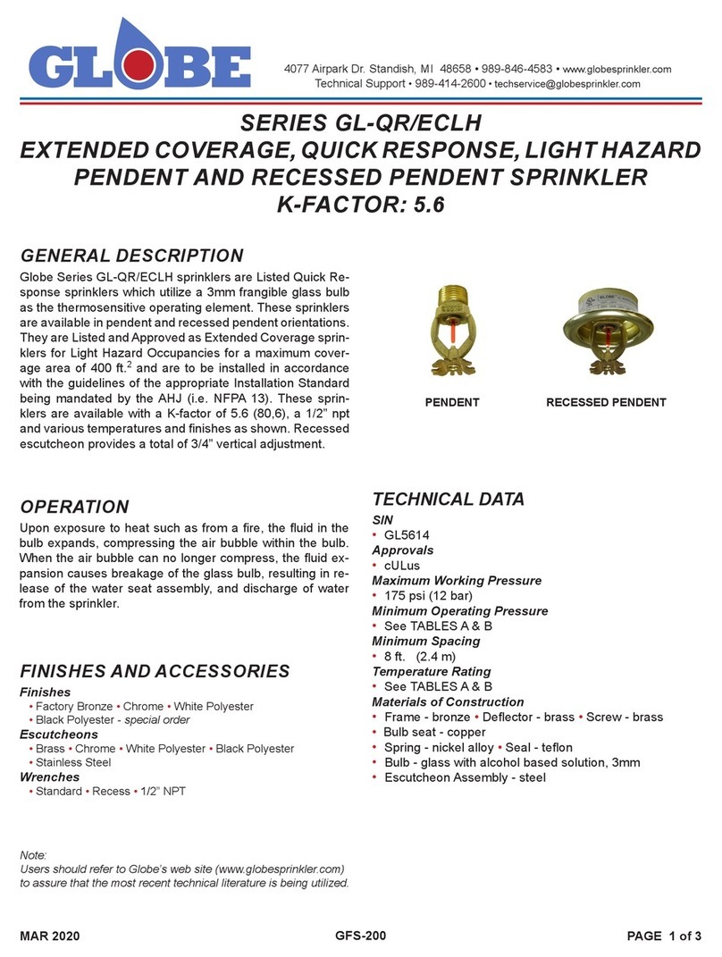
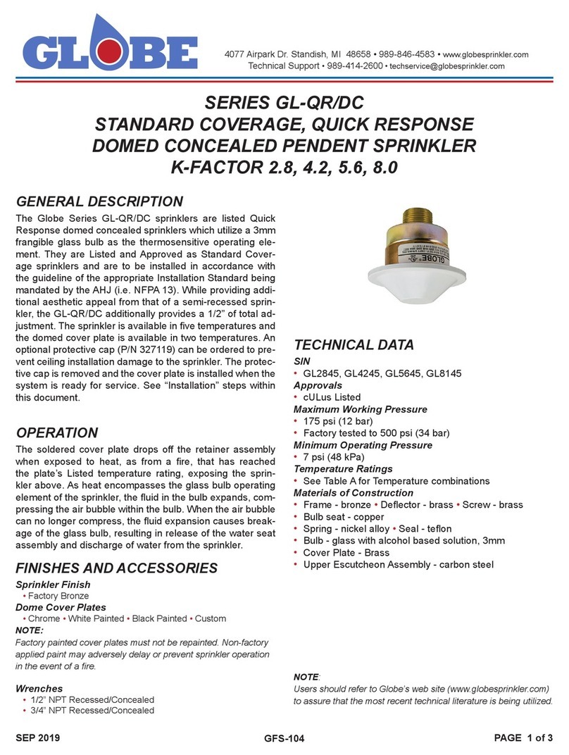
The Globe Series GL-QR/INCH/ECLH sprinkler is a Listed
Quick Response concealed sprinkler which utilizes a 3mm
frangible glass bulb as the thermosensitive operating ele-
ment. It is Listed and Approved as an Extended Coverage
sprinkler for Light Hazard Occupancies for a maximum cov-
erage area of 400 sq. ft. and is to be installed in accordance
with the guidelines of the appropriate Installation Standard
being mandated by the AHJ (i.e. NFPA 13). While providing
the optimal aesthetic appeal with the low prole at cover
plate, the GL-QR/INCH/ECLH additionally provides the larg-
est vertical adjustment in the industry of a nominal 1”. This
nominal 1” adjustment allows for previously unrecognized
installation exibility resulting in a clean and tight nal “t” to
the ceiling. The sprinkler is available in three temperatures
and the cover plate is available in two temperatures. The
nominal K-Factor is 5.6 (80,6) and the threads are 1/2” npt. TECHNICAL DATA
SIN
• GL5603
Approvals
• cULus - Light Hazard
Maximum Working Pressure
• 175 psi (12 bar)
Minimum Operating Pressure
• See TABLE A
Minimum Spacing
• 8 ft. (2.4 m)
Temperature Rating
• See TABLE A
Materials of Construction
• Frame - bronze • Deector - brass •Screw - brass
•Bulb seat - copper
• Spring - nickel alloy • Seal - teon
• Bulb - glass with alcohol based solution, 3mm
• Cover Plate - brass
• Upper Escutcheon Assembly - carbon steel
SERIES GL-QR/INCH/ECLH EXTENDED COVERAGE, QUICK RESPONSE,
LIGHT HAZARD CONCEALED PENDENT SPRINKLERS K-FACTOR: 5.6
SERIES GL-QR/ECLH/INCH/ECLH EXTENDED COVERAGE, QUICK RE-
SPONSE, LIGHT HAZARD CONCEALED PENDENT SPRINKLERS K-FAC-
TOR: 5.6
GFS-210 GFS-210
FINISHES AND ACCESSORIES
Sprinkler Finish
• Factory Bronze
Cover Plates
• Chrome •White Painted •Black Painted • Custom
Caution:
Factory painted cover plates must not be repainted. Non-factory
applied paint may adversely delay or prevent sprinkler operation
in the event of a re.
Wrench
• 1/2” NPT 1” Adjustable Concealed P/N 332765
OPERATION
The soldered cover plate drops o󰀨 the retainer assembly
when exposed to heat, as from a re, that has reached the
plate’s Listed temperature rating exposing the sprinkler
above. Upon the releasing of the cover plate, the deector,
which is connected to two guide pins, drops down below
the ceiling into its intended position. As heat encompasses
the glass bulb operating element of the sprinkler, the uid
in the bulb expands, compressing the air bubble within the
bulb. When the air bubble can no longer compress, the uid
expansion causes breakage of the glass bulb, resulting in
release of the water seat assembly, and discharge of water
from the sprinkler.
MAR 2020 GFS-210 PAGE 2 of 3
MAX. SPACING
ft. (m)
MIN. FLOW
gpm (lpm)
MIN. PRESSURE
psi (bar)
SPRINKER
TEMPERATURE RATING
COVER PLATE
TEMPERATURE
RATING
16 x 16 (4.9 x 4.9) 26 (98) 21.5 (1.48) 135°F, 155°F (57°C, 68°C) 135°F (57°C)
155°F, 175°F (68°C, 79°C) 155°F (68°C)
18 x 18 (5.5 x 5.5) 33 (125) 34.7 (2.39) 135°F, 155°F (57°C, 68°C) 135°F (57°C)
155°F, 175°F (68°C, 79°C) 155°F (68°C)
20 x 20 (6.1 x 6.1) 40 (151) 51.0 (3.52) 135°F (57°C) 135°F (57°C)
TABLE A: HYDRAULIC DESIGN AREA
Caution:
Do not install any bulb-type sprinkler if the bulb is cracked or
there is loss of liquid from the bulb. Sprinklers should be tightened
enough to obtain a leak-tight joint when water pressure is applied
and/or hydrostatic test is performed. Sprinklers should not be
overtightened as this can result in distortion and subsequent leak-
age. It is recommended not to exceed 14 ft.-lb. (19.0 Nm) torque
for 1/2 inch NPT threads.
INSTALLATION
FIGURE 1: ADJUSTABLE CONCEALED
WRENCH
P/N 332765
FIGURE 2: HAND HELD
INSTALLATION TOOL
P/N 332875
FIGURE 3:
INSTALLATION TOOL
USED WITH EXTENSION
P/N 332765
FIGURE 4: INSTALLED POSITION
Step 1. Install pendent sprinklers in the pendent
position, with the centerline of the sprinkler
perpendicular to the mounting surface.
Step 2. Remove the Protective Cap.
Step 3. With pipe-thread sealant applied to the pipe
threads, and using the Concealed Sprinkler
Wrench P/N 332765 (FIGURE 1), install and
tighten the Sprinkler/Concealed Cup Assembly
into the tting.
Step 4. Replace the Protective Cap by pushing it
upwards until it bottoms out against the Sup-
port Cup. The Protective Cap helps prevent
damage to the Deector and Drop Pins during
ceiling installation and/or during application of
the nish coating of the ceiling.
NOTICE:
The system is considered Out of Service when
the protective caps are in place.
Step 5. After the ceiling has been completed with the
2-3/4” (70mm) diameter hole, remove and
discard the Protective Cap and verify that the
Deector moves up and down freely. If the
sprinkler has been damaged or the deector
does not move up and down freely, replace
the entire sprinkler assembly. Do not attempt
to modify or repair.
Step 6. Push on the Cover Plate Assembly until its
ange contacts the ceiling. Never attempt to
screw on the Cover Plate Assembly such that
it lifts a ceiling panel out of its normal posi-
tion. If the Cover Plate Assembly cannot be
engaged with the Mounting Cup or the Cover
Plate Assembly cannot be engaged su󰀩cient-
ly to contact the ceiling, the Sprinkler Fitting
must be repositioned.
3 5/16" DIA.
2 3/4" MAX.
1 7/8" MIN.
1/8"
CEILING COVER PLATE
SUPPORT SHELL
CUP
DEFLECTOR
DROP PIN
1" x 1/2"
REDUCER
2 3/8" DIA.
CEILING
2 3/4" DIA. MIN.
HOLE IN CEILING
MAR 2020 GFS-210 PAGE 3 of 3
GLOBE®PRODUCT WARRANTY
Globe agrees to repair or replace any of its manufactured
products found to be defective in material or workmanship
for a period of one year from date of shipment.
For specic details of our warranty please refer to Price List
Terms and Conditions of Sale (Our Price List).
4077 Airpark Dr. Standish, MI 48658 • 989-846-4583 • www.globesprinkler.com
Technical Support •989-414-2600 •techservice@globesprinkler.com
ORDERING INFORMATION
SPECIFY
GL5603
SPRINKLER PART NUMBER
135°F (57°C) . . . . . . . . . . . . . . . . . . . . 560313501
155°F (68°C) . . . . . . . . . . . . . . . . . . . . 560315501
175°F (79°C) . . . . . . . . . . . . . . . . . . . . 560317501
COVER PLATES
SEE TABLE B
•Quantity •SIN •Temperature Rating •Finish •Part Number
• SPRINKLER
• PROTECTIVE CAP
•Quantity •Part Number 332871
• WRENCH
•Quantity •Part Number 332765
TABLE B: COVER PLATE PART NUMBERS
COVER PLATE
SIZE
WHITE
135°F (57°C)
CHROME
135°F (57°C)
WHITE
155°F (68°C)
CHROME
155°F (68°C)
BLACK
135°F (57°C)
BLACK
155°F (68°C)
CUSTOM
135°F (57°C)
CUSTOM
155°F (68°C)
3-5/16” DIA.332892 332891 332898 332897 332892-B 332898-B 332893 332899
CARE AND MAINTENANCE
Always obtain permission from the proper authorities to
shut down the a󰀨ected re protection system and notify all
personnel who may be a󰀨ected by this action before closing
a re protection system main control valve for maintenance
work on the system that it controls. Sprinklers should only
be cleaned by means of gently dusting with a feather dust-
er; otherwise, non-operation in the event of a re or inadver-
tent operation may result.
When properly installed, there is a nominal 1/8” (3mm) air
gap between the Cover Plate and the ceiling (FIGURE 4).
This air gap is necessary for proper operation of the sprin-
kler by allowing heat ow from a re to pass below and
above the Cover Plate to help assure appropriate release of
the Cover Plate in a re situation. This annular “gap” must
be maintained and should never be sealed or caulked.
Factory painted Cover Plates must not be repainted.
In accordance with NFPA 25, Sprinklers which are found to
be leaking or exhibiting visible signs of corrosion must be
replaced.
Automatic sprinklers must never be painted, plated, coated,
or otherwise altered after leaving the factory.
Care must be exercised to avoid damage to the sprinklers–
before, during, and after installation. Sprinklers damaged
by dropping, striking, wrench slippage, or similar incidents,
must be replaced.
The owner is responsible for the inspection, testing, and
maintenance of their re protection system and devices in
compliance with this document, as well as with the appli-
cable standards of the National Fire Protection Association
(e.g. NFPA 25), in addition to the standards of any other
authorities having jurisdiction.

This manual suits for next models

6

Other Globe Irrigation System manuals

Globe GL-RES/DC Series User manual

Globe

Globe GL-RES/DC Series User manual

Globe GL-QR/DC Series User manual

Globe

Globe GL-QR/DC Series User manual

Globe GL4247 Operating and installation instructions

Globe

Globe GL4247 Operating and installation instructions

Globe GL4231 User manual

Globe

Globe GL4231 User manual

Globe GL5614 User manual

Globe

Globe GL5614 User manual

Globe GL Series User manual

Globe

Globe GL Series User manual

Globe GL Series User manual

Globe

Globe GL Series User manual

Globe GL Series Installation guide

Globe

Globe GL Series Installation guide

Globe GL-RES Series User manual

Globe

Globe GL-RES Series User manual

Globe GL3010 User manual

Globe

Globe GL3010 User manual

Globe GL Series User manual

Globe

Globe GL Series User manual

Globe GL-RES/SW Series User manual

Globe

Globe GL-RES/SW Series User manual

Globe GL-QR/ECLH Series User manual

Globe

Globe GL-QR/ECLH Series User manual

Popular Irrigation System manuals by other brands

Tyco TY-L Series quick start guide

Tyco

Tyco TY-L Series quick start guide

Tyco Fire Product CENTRAL Omega HEC-12 instruction manual

Tyco Fire Product

Tyco Fire Product CENTRAL Omega HEC-12 instruction manual

Bionix Aquabot OtoClear 7270 Instructions for use

Bionix

Bionix Aquabot OtoClear 7270 Instructions for use

FLINQ FQC8284 instruction manual

FLINQ

FLINQ FQC8284 instruction manual

claber 8063 manual

claber

claber 8063 manual

Viking FREEDOM VK498 Technical data

Viking

Viking FREEDOM VK498 Technical data

Tyco Rapidresponse LFII Series quick start guide

Tyco

Tyco Rapidresponse LFII Series quick start guide

Tyco rapidresponse RSV-1 quick start guide

Tyco

Tyco rapidresponse RSV-1 quick start guide

Tyco DS-1 Series manual

Tyco

Tyco DS-1 Series manual

Tyco ESFR-17 quick start guide

Tyco

Tyco ESFR-17 quick start guide

Tyco RAPID RESPONSE Series quick start guide

Tyco

Tyco RAPID RESPONSE Series quick start guide

Reliable G5-56 Dry manual

Reliable

Reliable G5-56 Dry manual

AQUAJOE AJ-ISSS user manual

AQUAJOE

AQUAJOE AJ-ISSS user manual

K-Rain RPS 46 instruction manual

K-Rain

K-Rain RPS 46 instruction manual

AQUAJOE SJI-OMS18 quick guide

AQUAJOE

AQUAJOE SJI-OMS18 quick guide

Reliable F1FR Series Bulletin

Reliable

Reliable F1FR Series Bulletin

HYDRO-RAIN ORBIT SPRINKLER SYSTEM DESIGNER installation guide

HYDRO-RAIN

HYDRO-RAIN ORBIT SPRINKLER SYSTEM DESIGNER installation guide

Viking MICROFAST M Technical data

Viking

Viking MICROFAST M Technical data

manuals.online logo
manuals.online logoBrands
  • About & Mission
  • Contact us
  • Privacy Policy
  • Terms and Conditions

Copyright 2025 Manuals.Online. All Rights Reserved.