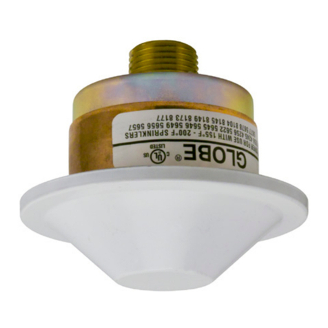
Globe GL-QR/DC Series User manual

SEP 2019 GFS-104 PAGE 1 of 3
SERIES GL-QR/DC
STANDARD COVERAGE, QUICK RESPONSE
DOMED CONCEALED PENDENT SPRINKLER
K-FACTOR 2.8, 4.2, 5.6, 8.0
4077 Airpark Dr. Standish, MI 48658 • 989-846-4583 • www.globesprinkler.com
Technical Support •989-414-2600 •techservice@globesprinkler.com
NOTE:
Users should refer to Globe’s web site (www.globesprinkler.com)
to assure that the most recent technical literature is being utilized.
GENERAL DESCRIPTION
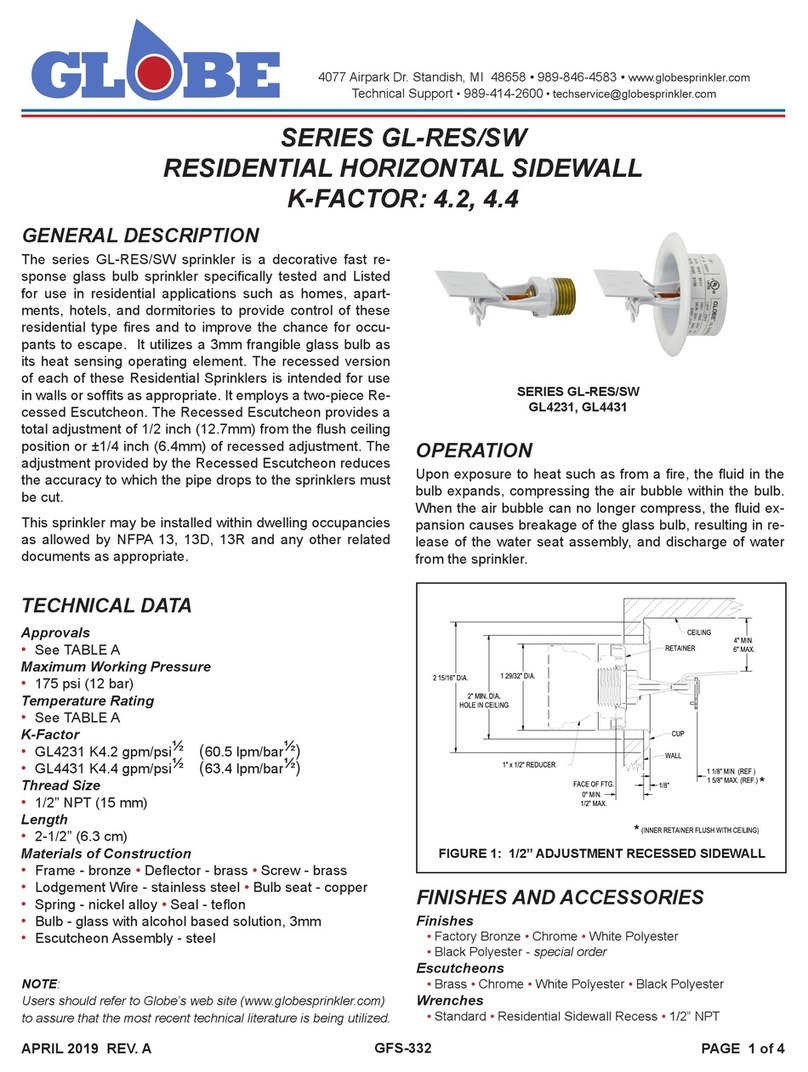
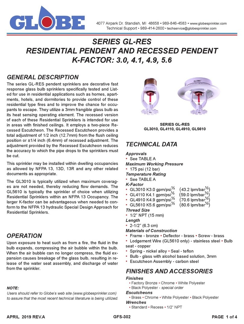
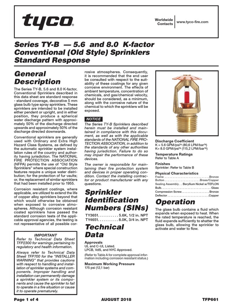
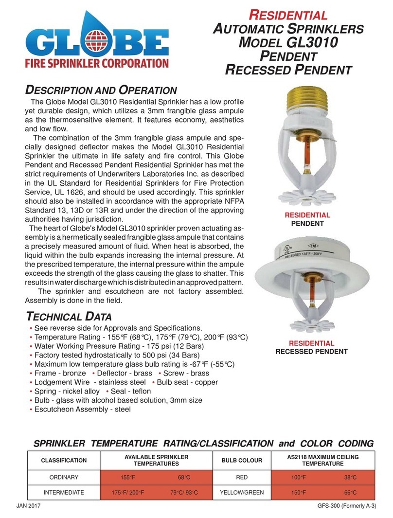
The Globe Series GL-QR/DC sprinklers are listed Quick
Response domed concealed sprinklers which utilize a 3mm
frangible glass bulb as the thermosensitive operating ele-
ment. They are Listed and Approved as Standard Cover-
age sprinklers and are to be installed in accordance with
the guideline of the appropriate Installation Standard being
mandated by the AHJ (i.e. NFPA 13). While providing addi-
tional aesthetic appeal from that of a semi-recessed sprin-
kler, the GL-QR/DC additionally provides a 1/2” of total ad-
justment. The sprinkler is available in ve temperatures and
the domed cover plate is available in two temperatures. An
optional protective cap (P/N 327119) can be ordered to pre-
vent ceiling installation damage to the sprinkler. The protec-
tive cap is removed and the cover plate is installed when the
system is ready for service. See “Installation” steps within
this document.
OPERATION
The soldered cover plate drops off the retainer assembly
when exposed to heat, as from a re, that has reached
the plate’s Listed temperature rating, exposing the sprin-
kler above. As heat encompasses the glass bulb operating
element of the sprinkler, the uid in the bulb expands, com-
pressing the air bubble within the bulb. When the air bubble
can no longer compress, the uid expansion causes break-
age of the glass bulb, resulting in release of the water seat
assembly and discharge of water from the sprinkler.
TECHNICAL DATA
SIN
• GL2845, GL4245, GL5645, GL8145
Approvals
• cULus Listed
Maximum Working Pressure
• 175 psi (12 bar)
• Factory tested to 500 psi (34 bar)
Minimum Operating Pressure
• 7 psi (48 kPa)
Temperature Ratings
• See Table A for Temperature combinations
Materials of Construction
• Frame - bronze • Deector - brass •Screw - brass
• Bulb seat - copper
• Spring - nickel alloy • Seal - teon
• Bulb - glass with alcohol based solution, 3mm
• Cover Plate - Brass
• Upper Escutcheon Assembly - carbon steel
FINISHES AND ACCESSORIES
Sprinkler Finish
• Factory Bronze
Dome Cover Plates
• Chrome •White Painted •Black Painted • Custom
NOTE:
Factory painted cover plates must not be repainted. Non-factory
applied paint may adversely delay or prevent sprinkler operation
in the event of a re.
Wrenches
• 1/2” NPT Recessed/Concealed
• 3/4” NPT Recessed/Concealed
SERIES GL-QR/DC STANDARD COVERAGE, QUICK RESPONSE
DOMED CONCEALED PENDENT SPRINKLER
K-FACTOR: 2.8, 4.2, 5.6, 8.0
SERIES GL-QR/DC STANDARD COVERAGE, QUICK RESPONSE
DOMED CONC EALED PENDENT SPRINKLER
K-FACTOR: 2.8, 4.2, 5.6, 8.0
GFS-104 GFS-104
SEP 2019 GFS-104 PAGE 2 of 3
INSTALLATION
Step 1. Install pendent sprinklers in the pendent
position, with the centerline of the sprinkler
perpendicular to the mounting surface.
Step 2. Remove the Protective Cap.
Step 3. With pipe-thread sealant applied to the pipe
threads, and using the Concealed Sprinkler
Wrench P/N 325391 or P/N 325401 (FIGURE
2), install and tighten the Sprinkler/Concealed
Cup Assembly into the tting.
Step 4. Replace the Protective Cap by pushing it
upwards until it bottoms out against the Sup-
port Cup. The Protective Cap helps prevent
damage to the Deector and Drop Pins during
ceiling installation and/or during application of
the nish coating of the ceiling.
NOTICE:
The system is considered Out of Service when
the protective caps are in place.
Step 5. After the ceiling has been completed with the
2-1/2” (63.2mm) diameter hole, remove and
discard the Protective Cap and verify that the
Deector has not been damaged. If the sprin-
kler has been damaged , replace the entire
sprinkler assembly. Do not attempt to modify
or repair.
Step 6. Thread on the Cover Plate Assembly until its
ange contacts the ceiling. Never attempt to
screw on the Cover Plate Assembly such that
it lifts a ceiling panel out of its normal posi-
tion. If the Cover Plate Assembly cannot be
engaged with the Mounting Cup or the Cover
Plate Assembly cannot be engaged sufcient-
ly to contact the ceiling, the Sprinkler Fitting
must be repositioned.
NOTICE
Do not install any bulb-type sprinkler if the bulb is cracked or
there is loss of liquid from the bulb. Sprinklers should be tightened
enough to obtain a leak-tight joint when water pressure is applied
and/or hydrostatic test is performed. Sprinklers should not be
overtightened as this can result in distortion and subsequent leak-
age. It is recommended not to exceed 14 ft.-lb. (19.0 Nm) torque
for 1/2 inch NPT sprinkler threads; 20 ft.-lb. (26.8 Nm) to 3/4 inch
NPT threads.
FIGURE 1: 1/2” ADJUSTMENT DOMED PLATE
CONCEALED PENDENT
INSTALLATION DIMENSIONS
FIGURE 2: CONCEALED WRENCH
½” NPT P/N 325391
¾” NPT P/N 325401
SIN GL2845 GL4245 GL5645 GL8145
K-FACTOR 2.8 (40 metric) 4.2 (60 metric) 5.6 (80 metric) 8.0 (115 metric)
NPT 1/2” (15mm) 1/2” (15mm) 1/2” (15mm) 3/4” (20mm)
COVER PLATE 135°F (57°C) 155°F (68°C) 135°F (57°C) 155°F (68°C) 135°F (57°C) 155°F (68°C) 155°F (68°C)
SPRINKLER
TEMPERATURE
135°F (57°C)
155°F (68°C)
155°F (68°C)
200°F (93°C)
135°F (57°C)
155°F (68°C)
155°F (68°C)
200°F (93°C)
135°F (57°C)
155°F (68°C)
155°F (68°C)
175°F (79°C)
200°F (93°C)
155°F (68°C)
175°F (79°C)
200°F (93°C)
TABLE A: cULus LISTING

SEP 2019 GFS-104 PAGE 3 of 3
TABLE B: DOMED COVER PLATE PART NUMBERS
DOMED COVER
PLATE SIZE
WHITE
135°F (57°C)
CHROME
135°F (57°C)
WHITE
155°F (68°C)
CHROME
155°F (68°C)
BLACK
135°F (57°C)
BLACK
155°F (68°C)
CUSTOM
135°F (57°C)
CUSTOM
155°F (68°C)
3-1/4” DIA.326048 326046 326053 326051 326048-B 326053-B 326049 326054
GLOBE®PRODUCT WARRANTY
Globe agrees to repair or replace any of its manufactured
products found to be defective in material or workmanship
for a period of one year from date of shipment.
For specic details of our warranty please refer to Price List
Terms and Conditions of Sale (Our Price List).
4077 Airpark Dr. Standish, MI 48658 • 989-846-4583 • www.globesprinkler.com
Technical Support •989-414-2600 •techservice@globesprinkler.com
ORDERING INFORMATION
SPECIFY
GL2846
SPRINKLERS PART NUMBER
135°F (57°C) . . . . . . . . . . . . . . . . . . . . 284613501
155°F (68°C) . . . . . . . . . . . . . . . . . . . . 284615501
175°F (79°C) . . . . . . . . . . . . . . . . . . . . 284617501
200°F (93°C) . . . . . . . . . . . . . . . . . . . . 284620001
GL4245
SPRINKLERS PART NUMBER
135°F (57°C) . . . . . . . . . . . . . . . . . . . . 424513501
155°F (68°C) . . . . . . . . . . . . . . . . . . . . 424515501
175°F (79°C) . . . . . . . . . . . . . . . . . . . . 424517501
200°F (93°C) . . . . . . . . . . . . . . . . . . . . 424520001
GL5645
SPRINKLERS PART NUMBER
135°F (57°C) . . . . . . . . . . . . . . . . . . . . 564513501
155°F (68°C) . . . . . . . . . . . . . . . . . . . . 564515501
175°F (79°C) . . . . . . . . . . . . . . . . . . . . 564517501
200°F (93°C) . . . . . . . . . . . . . . . . . . . . 564520001
GL8145
SPRINKLERS PART NUMBER
135°F (57°C) . . . . . . . . . . . . . . . . . . . . 814513501
155°F (68°C) . . . . . . . . . . . . . . . . . . . . 814515501
175°F (79°C) . . . . . . . . . . . . . . . . . . . . 814517501
200°F (93°C) . . . . . . . . . . . . . . . . . . . . 814520001
COVER PLATES
SEE TABLE B
•Quantity •SIN •Temperature Rating •Finish •Part Number
• SPRINKLER
• PROTECTIVE CAP
•Quantity •Part Number 327119
• WRENCH
•Quantity •Part Number
1/2” NPT . . . . . . . . . . . . . . . . . . . . . . 325391
3/4” NPT . . . . . . . . . . . . . . . . . . . . . . 325401
CARE AND MAINTENANCE
Prior to installation, it is important to read and follow the
“Sprinkler Caution” sheet (GFS-840) included within each
box of sprinklers. This sheet is available on Globe’s web
site (www.globesprinkler.com).
Store sprinklers in a cool, dry place. Exposure to extreme
heat will damage the thermal sensing element, possibly re-
sulting in premature activation. Avoid direct sunlight.
Replace any sprinkler that shows any corrosion, damage,
or loss of liquid from the glass bulb.
Do not attempt to paint or alter the sprinkler’s coating or
cover plate in any manner after leaving the manufacturing
plant.
Do not attach wiring, ropes, decorations or xtures to a
sprinkler.
Absence of an escutcheon, used to cover a ceiling hole,
may delay sprinkler operation in a re situation.
It is the owner’s responsibility for inspection, testing and
maintenance of the re sprinkler system with all components
and devices in accordance with the National Fire Protection
Association Pamphlet 25 as well as any other requirements
as set forth by the local Authority Having Jurisdiction (AHJ).
This manual suits for next models
5
Table of contents
Other Globe Irrigation System manuals

Globe
Globe GL Series User manual

Globe
Globe GL Series User manual

Globe
Globe GL3010 User manual

Globe
Globe GL-RES/SW Series User manual

Globe
Globe GL-RES Series User manual

Globe
Globe GL-QR/ECLH Series User manual

Globe
Globe GL Series User manual

Globe
Globe GL Series Installation guide

Globe
Globe GL4247 Operating and installation instructions

Globe
Globe GL4231 User manual