206M 201805
7
Caution: When clamp the wheel rim, don't put your hands on the wheel rim to avoid injury during this operation.
Lock the Hexagonal Vertical Mounting Arm, put the tyre on the rim, let the Rocker Arm back to place as demounting the
tyre. And let one side of tyre down bead above the rear section of the Mounting/demounting head, the other side under the
front section of the Mounting/demounting head. Suppress the trye with hands or help arm, and then spin the turntable for
mounting the tyre down bead.
Repeat the above operation for mounting the tyre up bead. (Fig7)
10.Inflatingthetire:
Importance: It is very dangerous during inflating operation, take carefully and comply with instruction. When inflating, it
will turn to be extremely dangerous if problems happen to tyre or rim. The possible burst force tire goes upward and
outward, the big power may cause injury or death of the operator or the people around.
Tyre may burst caused by following:
1) The wheel rim and the tyre are not of the same size;
2) The tyre or the wheel rim is damaged;
3) The pressure of tyre inflation is over the max. pressure recommended by manufacturer;
4) The operator fail to comply with the safety regulation;
Please operate as follows:
1) Remove the valve cap from the valve stem;
2) Check to make sure the air nozzle is pressed down completely over the threads of the
valve stem.
3) Check to make sure that the tyre and the wheel rim are of the same size;
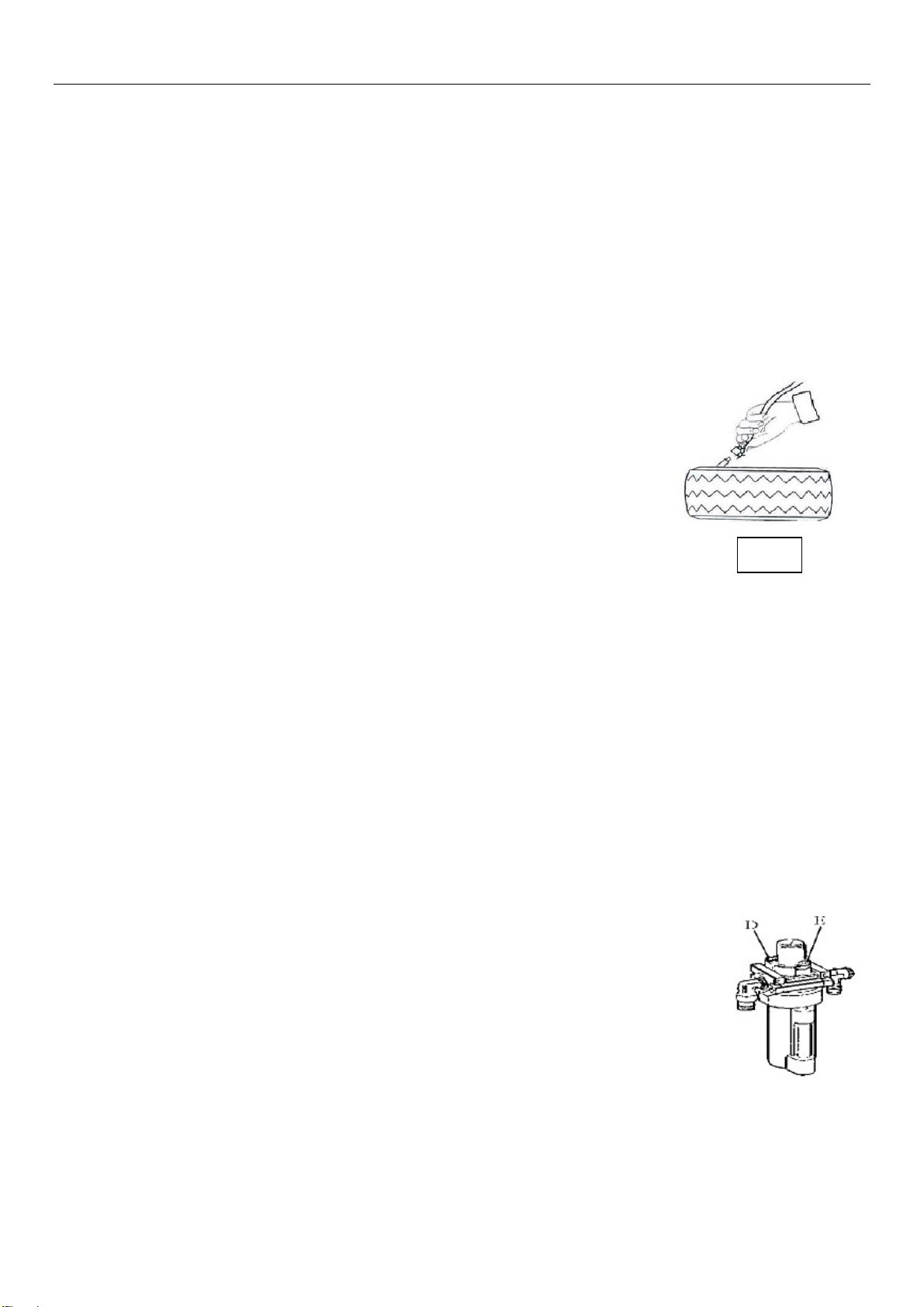
4) Lubricate both the tyre bead and the wheel rim, additional lubrication is required if needed;
5) Inflate the tyre with break, while inflating, check the pressure listed on the pressure gauge, also check whether the bead is
fixed or not. Repeat operation above until the bead is secured; you need take special steps when inflating convex rim or
double convex rim;
6) Continue inflating and check the air pressure frequently until to reach the required pressure.
Note:
Never exceed the max. inflation pressure given by the tyre manufacturer.
Keep hands and your body away from inflating tyres.
Only specially trained persons are allowed to perform the operations, do not allow other to operate or be near the
tyre changer.
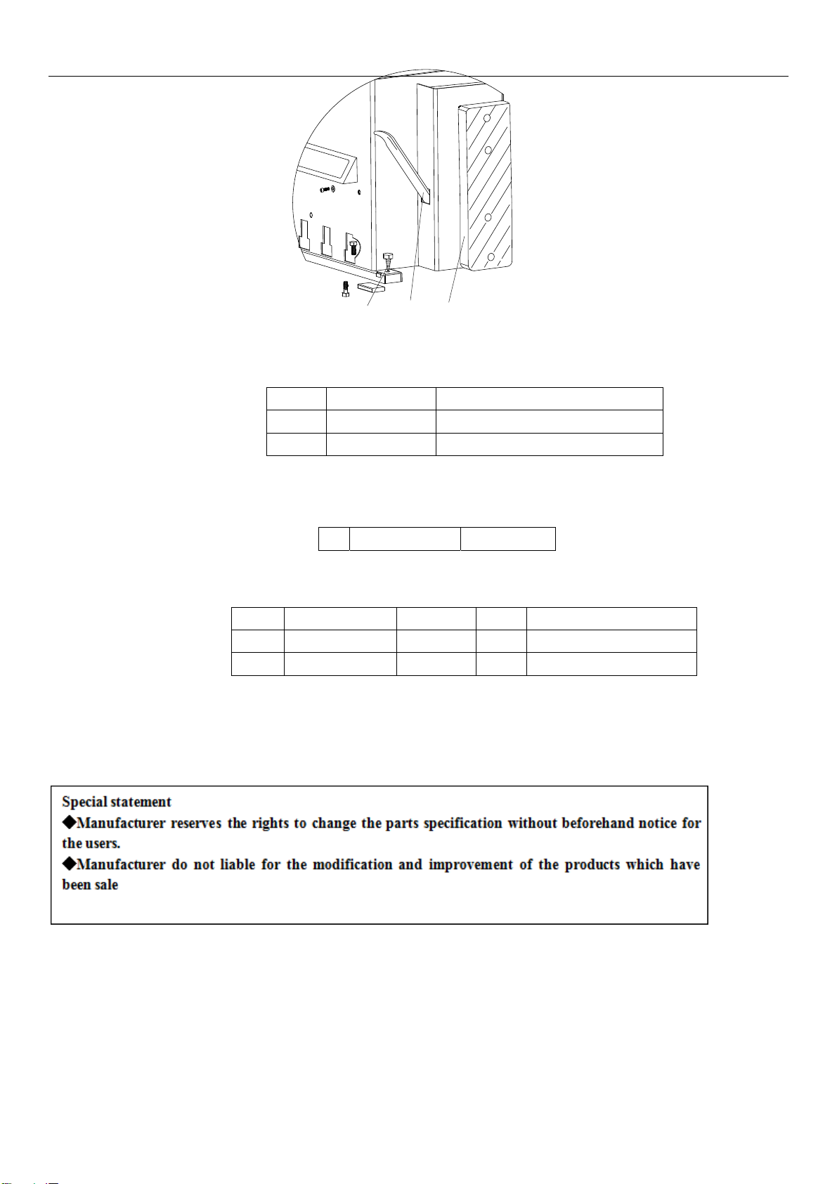
11. Moving machine:
Please use forklift to move the machine. Disconnect the tyre changer from the electricity power
supply and pneumatic power supply, lift the base board and insert the feet of forklift. Then mount
the tyre changer machine to a new position and fix it tightly.
Note: the place chosen for fixing the tyre changer must meet the safety regulation.
12. Maintenance:
Caution: only the professional persons can do the maintenance. To prolong the machine's life,
maintain the machine timely according to the manual. Otherwise, it will impact the reliability of the
machineorevencauseinjurytooperatorandothersnearby. Fig9
Caution: before performing any maintenance, disconnect the tyre changer from the electric power supply and
pneumatic power supply, and tread the Jaws open and close Pedal or Turntable Rotation Pedal for 3~4 times to
evacuate all compressed air from the machine. Damaged parts must be replaced by professional persons with the
Fig 8