GLW PC 65 User manual

OPERATING INSTRUCTIONS
EN
Ausgabedatum: 2019
-
05
-
23
Ver. 1.0, DE / EN / IT / FR


Table of contents
PC 65 Crimper Operating Instructions Vers. 1.0 Page 3 of 39
Tab e of contents
1 General information ............................................................................. 6
1.1
About the operating instructions ................................................................. 6
1.2
Keeping the operating instructions at hand ................................................ 6
1.3
Target group ............................................................................................... 6
1.4
Validity ........................................................................................................ 6
1.5
Guarantee and warranty ............................................................................. 6
1.6
Limitation of liability ..................................................................................... 6
1.7
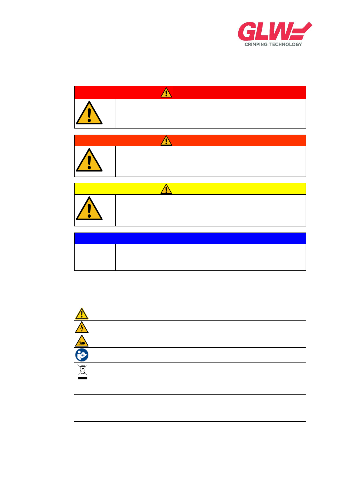
Signs and symbols ...................................................................................... 6
1.7.1
Safety instructions ......................................................................................... 7
1.7.2
Other conventions ......................................................................................... 7
2 General safety instructions ................................................................... 8
2.1
Intended use ............................................................................................... 8
2.2
Use of the equipment for purposes other than the intended use ............... 8
2.3
Foreseeable misuse ................................................................................... 8
2.4
Declaration of conformity / Declaration of incorporation ............................. 8
2.5
General sources of hazards........................................................................ 8
2.6
Hazards posed by electrical energy ........................................................... 8
2.7
Hazards posed by pneumatic energy ......................................................... 8
2.8
Proper conduct during emergencies ........................................................... 9
2.9
Responsibilities of the operating company ................................................. 9
2.10
Safety equipment ........................................................................................ 9
2.11
Safety markings/labels on the equipment ................................................... 9
2.12
Qualification of the personnel ..................................................................... 9
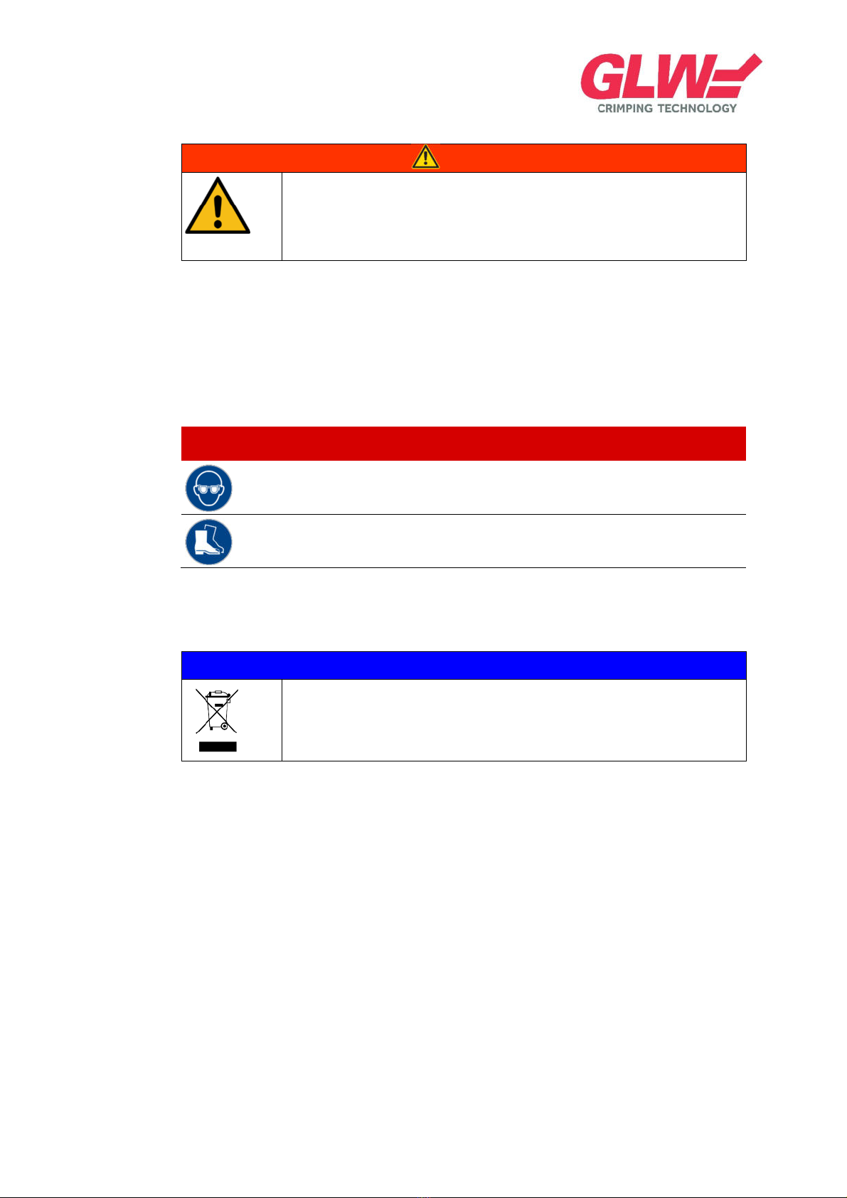
2.13
Personal protective equipment ................................................................. 10
2.14
Environmental protection .......................................................................... 10
3 Transport and storage ........................................................................ 11
3.1
Transporting the equipment ...................................................................... 11
4 Product description ............................................................................ 12
4.1
Scope of supply ........................................................................................ 12
4.2
Overview ................................................................................................... 12
4.3
Accessories............................................................................................... 13
4.4
Safety equipment ...................................................................................... 13
4.4.1
Protective cover ........................................................................................... 13
4.5
Control and display elements ................................................................... 14
4.5.1
Starting up the PC 65 .................................................................................. 14
4.5.2
Operating the foot pedal (crimping) ............................................................. 15
4.5.3
Operating pressure ...................................................................................... 15

Table of contents
PC 65 Crimper Operating Instructions Vers. 1.0 Page 4 of 39
4.5.4
Unlocking the display .................................................................................. 16
4.5.5
Starting up the PC 65 (operating mode 2) ................................................... 16
4.5.6
Operating the foot pedal (operating mode 2) ............................................... 17
4.5.7
Switching from standard to setting on-screen display ................................. 18
4.5.8
Saving the opening angle of the crimp die .................................................. 19
4.5.9
Loading saved opening angles .................................................................... 19
4.5.10
Locking the display ...................................................................................... 20
4.5.11
Setting the minimum pressure ..................................................................... 20
4.5.12
Setting the max. pressure ........................................................................... 21
4.5.13
Editing the lock code ................................................................................... 21
4.5.14
Requesting a service code .......................................................................... 22
4.5.15
Selecting the language ................................................................................ 22
5 Installation and commissioning/start up .............................................. 23
5.1
Establishing energy supply ....................................................................... 23
5.1.1
Pneumatic installation ................................................................................. 23
5.1.2
Electrical installation .................................................................................... 24
5.2
Commissioning ......................................................................................... 24
5.2.1
Starting up the PC 65 crimper ..................................................................... 24
5.2.2
Shutting down the PC 65 crimper ................................................................ 25
5.2.3
Operating the foot pedal .............................................................................. 27
5.2.4
Setting the operating pressure .................................................................... 28
5.3
Installation and adjustment of the crimp die ............................................. 28
6 Operating modes of the PC 65 crimper .............................................. 29
6.1
Operating mode 1 ..................................................................................... 29
6.1.1
Crimping in one step (button 1) ................................................................... 29
6.2
Operating mode 2 ..................................................................................... 29
6.2.1
Crimping in two steps (button 1) .................................................................. 29
6.2.2
Saving the opening angle of the crimp die .................................................. 30
6.2.3
Loading saved opening angles .................................................................... 30
6.2.4
Locking the display ...................................................................................... 30
6.2.5
Unlocking the display .................................................................................. 30
6.2.6
Changing lock codes ................................................................................... 31
6.2.7
Setting the operating pressure .................................................................... 31
6.2.8
Cancelling the contact fixing process .......................................................... 32
6.2.9
Selecting the language ................................................................................ 32

Table of contents
PC 65 Crimper Operating Instructions Vers. 1.0 Page 5 of 39
7 Error messages ................................................................................. 33
7.1
Operating pressure is too low ................................................................... 33
7.2
Operating pressure is too high.................................................................. 33
7.3
Decommissioning ..................................................................................... 33
8 Technical specifications ..................................................................... 34
8.1
Technical specifications ............................................................................ 34
8.2
Rating plate ............................................................................................... 34
9 Instructions regarding cleaning, maintenance and disassembly ......... 35
9.1
Cleaning .................................................................................................... 35
9.2
Maintenance and repair ............................................................................ 35
9.3
Dismantling and disposal .......................................................................... 35
9.4
Recycling .................................................................................................. 35
10 Service, spare parts and accessories................................................. 36
10.1
Customer service ...................................................................................... 36
10.2
Spare parts ............................................................................................... 36
10.3
Accessories............................................................................................... 36
10.3.1
Crimp dies ................................................................................................... 36
10.3.2
Protective cover ........................................................................................... 37
10.3.3
Locator unit.................................................................................................. 37
11 Declaration of Conformity ................................................................... 38
12 Copyright ........................................................................................... 39

1 General information
PC 65 Crimper Operating Instructions Vers. 1.0 Page 6 of 39
1 Genera information
This section provides general information regarding these operating instructions.
1.1 About the operating instructions
Please read the operating instructions carefully and keep them for future reference.
These operating instructions contain important details about the safe and hazard-free use of the equip-
ment.
Prior to using this equipment, the operating personnel must make themselves familiar with the operating
instructions and the product.
Adhering to all safety instructions is the fundamental requirement for the application of the PC 65 crimper.
The operating instructions are an integral part of the product, and must therefore be passed on in case
the equipment is sold, disposed of or moved to a different site.
The German version is the original version of the operating instructions.
1.2 Keeping the operating instructions at hand
The operating instructions must be stored in direct proximity to the product and must be easily accessible
to the operating and maintenance personnel at all times.
The operating instructions must be retained until the disposal of the product.
1.3 Target group
These operating instructions are directed to the operating company’s operating and maintenance per-
sonnel for the equipment. Only instructed and trained personnel is allowed to operate and maintain this
equipment.
1.4 Va idity
These operating instructions apply to the overall PC 65 crimper unit and all accessories offered at this
point in time.
1.5 Guarantee and warranty
Guarantees and warranties within the scope of the general statutory guarantee and warranty regulations
apply.
Furthermore, additional agreements to be found in the sales documents apply.
No changes, additions or modifications may be made to the product without prior approval by the man-
ufacturer.
Only use original spare parts, otherwise the warranty shall lapse with immediate effect.
1.6 Limitation of iabi ity
The following is generally excluded from the liability:
Failing to follow the operating instructions
Use of the equipment for purposes other than the intended use
Use of unapproved wear or spare parts
Deployment of unqualified personnel without training
Unauthorised modifications to the equipment are prohibited for reasons related to safety and
liability, otherwise the conformity declaration shall lapse with immediate effect.
1.7 Signs and symbo s

1 General information
PC 65 Crimper Operating Instructions Vers. 1.0 Page 7 of 39
The following signs and symbols are used in these operating instructions.
1.7.1 Safety instructions
DANGER
It indicates an imminent threat of danger. If operating instructions, work
instructions, prescribed work processes and such are not or not properly
followed, it will result in very serious (disablement) or even fatal injuries.
WARNING
It indicates a potentially hazardous situation. If the situation is not avoided, a risk
of sustaining very serious or even fatal injuries may be posed. Furthermore, it
may lead to equipment and material damage.
CAUTION
This symbol indicates a potentially hazardous situation. If operating instructions,
work instructions, prescribed work processes and such are not or not properly
followed, it will result in injuries and/or damage to the equipment.
NOTICE
This symbol denotes application advice for users and other helpful information.
Following these instructions generally makes the job easier.
1.7.2 Other conventions
General hazard
Hazards posed by electricity
Hazards posed by the risk of getting crushed
Operating instructions
Disposal of old electrical and electronic devices
1., 2…
Instructions
Outcome of the instructions
Averting the hazard

2 General safety instructions
PC 65 Crimper Operating Instructions Vers. 1.0 Page 8 of 39
2 Genera safety instructions
This section provides general information regarding the safe operation of this equipment.
2.1 Intended use
The PC 65 crimper is used to crimp contacts.
The crimp dies are part of the accessories, allowing the equipment to produce a wide range of different
crimp connections. Only approved crimp dies must be used in the process.
The wide spectrum of the equipment also qualifies for the application in workshops as well as in complex
cable confection systems.
It is only allowed to be used on dry and clean production sites.
Intended use of the equipment also includes adherence to the operating instructions and compliance
with inspection and maintenance requirements.
Furthermore, intended use includes adherence to supplier documentation.
Any other use shall be deemed as improper use. GLW shall not assume liability for any damage resulting
from improper use.
2.2 Use of the equipment for purposes other than the intended use
If the equipment is operated without meeting the specifications, it shall be deemed improper use.
Use of unapproved materials.
Use of the equipment during ongoing strong vibrations at the installation site.
2.3 Foreseeab e misuse
Misuse may include:
Failing to follow the operating instructions
2.4 Dec aration of conformity / Dec aration of incorporation
This product conforms with the 2016/42/EC Directive. This was verified with a risk assessment, and the
Declaration of Conformity has been issued. A duplication of the Declaration of Conformity is enclosed in
section 11, page 38. Declaration of Conformity
2.5 Genera sources of hazards
The following hazard sources can be identified for the handling of the equipment:
electrical energy
pneumatic energy
application without the protective cover
hazards posed by components lying around in the work area
2.6 Hazards posed by e ectrica energy
Work on electrical systems or equipment must be carried out by professional electricians or trained per-
sonnel under the guidance and supervision of a professional electrician in accordance with current elec-
trical engineering practices and regulations.
2.7 Hazards posed by pneumatic energy

2 General safety instructions
PC 65 Crimper Operating Instructions Vers. 1.0 Page 9 of 39
Work on pneumatic systems or equipment must be carried out by pneumatic specialists or trained per-
sonnel under the guidance and supervision of a pneumatic specialist in accordance with current pneu-
matic engineering practices and regulations.
2.8 Proper conduct during emergencies
In case of an emergency, disconnect the equipment from the power supply and shut it off. If the equip-
ment is damaged, inform your superior without delay.
2.9 Responsibi ities of the operating company
The operating company is the party operating the machine or equipment for commercial and economic
purposes, or making it available to third parties for use.
This ensues the following obligations for the operating company:
to be familiar and implement occupational health and safety regulations
to carry out a risk assessment
to train and instruct personnel accordingly and on a regular basis about hazards posed
to provide the necessary protective equipment
to prepare instructions for the proper handling of the equipment
to clearly direct and assign responsibilities of the personnel
the assigned personnel must have read the operating instructions before starting up the equip-
ment
In addition, obligations from other policies applicable on site apply accordingly.
2.10 Safety equipment
The device features the following safety equipment:
Protective cover
The device must not be operated without the protective cover.
2.11 Safety markings/ abe s on the equipment
Marking/label Location
This marking/label is located on the protective cover of the equipment.
WARNING
Risk of injury by being crushed.
Operating the equipment without the protective cover may lead to personal
injuries or damage to property.
Never carry out any work without the protective cover in place.
2.12 Qua ification of the personne
Only trained and instructed personnel is allowed to operate the equipment.

2 General safety instructions
PC 65 Crimper Operating Instructions Vers. 1.0 Page 10 of 39
WARNING
Inadequate qualification of the personnel poses a risk of injury.
Improper handling of the equipment may lead to serious personal injuries and
property damage.
All work must only be carried out by personnel who are qualified to do so.
Otherwise, a specialist must be hired to carry out the work.
Instructed personne
Instructed personnel are personnel who have been instructed by the operating company in detail and
verifiably about their assigned tasks and the potential risks.
2.13 Persona protective equipment
Symbol Description Category
Safety goggles with side guards
II
Protective footwear
II
2.14 Environmenta protection
NOTICE
The environmental and health regulations must be followed and require
appropriate conduct.
For further details, refer to section 9.3 Dismantling and disposal in the supplier documentation and the
relevant safety data sheets.

3 Transport and storage
PC 65 Crimper Operating Instructions Vers. 1.0 Page 11 of 39
3 Transport and storage
3.1 Transporting the equipment
The equipment must be transported with a utility vehicle.
A pallet, a pallet cardboard box or a cardboard box may be used as packaging, depending on the type,
quantity and size of the components to be transported.
NOTICE
We recommend to use the original operating instructions or the relevant
translation of the suppliers (purchased parts).
For transport overseas, packaging appropriate for oversea transport must be
used.

4 Product description
PC 65 Crimper Operating Instructions Vers. 1.0 Page 12 of 39
4 Product description
4.1 Scope of supp y
Fig. 1: Scope of supply
Legend
Item Description Item Description
1 Foot pedal 4 PC 65 crimper equipment
2 Protective cover 5 Operating instructions
3 Power supply unit 12 VAC, 500 mA, 6.0 W
max.
4.2 Overview
Fig. 2: Front Fig. 3: Back
Legend
Item Description Item Description
1 Display 1 Compressed air maintenance unit
2 Crimp lever 2 Pneumatic connection
3 Crimp die 3 Foot pedal connection
4 Protective cover 4 12 VAC power supply
5 Carrier handle 5 Signal output for PC 65 accessories
6 Rocker switch “ON / OFF”
7 Power supply unit 12 VAC, 500 mA, 6.0 W
max.

4 Product description
PC 65 Crimper Operating Instructions Vers. 1.0 Page 13 of 39
The PC 65 crimper is used to crimp contacts.
A protective cover with an accurately fitted insertion slot is provided for each crimp die. For this purpose,
also refer to www.glw.de/crimper.
The PC 65 will only work if the protective cover is inserted completely.
The protective cover protects against injuries to fingers and hands in the hazard zone of the crimp die
and against damage from the outside.
Pressing the foot pedal initiates the crimp process.
The foot pedal must remain pressed until the crimp die is closed completely (operating mode 1) or the
crimp contact is clamped tightly (operating mode 2).
4.3 Accessories
NOTICE
With the use of accessories from other suppliers, the warranty shall lapse.
If failing to comply, the Declaration of Conformity for this equipment shall lapse
with immediate effect.
Accessories can be ordered via [email protected].
4.4 Safety equipment
4.4.1 Protective cover
The protective cover (1) protects the operator against being crushed and the crimp die (6) against dam-
age from the outside.
Fig. 4: Protective cover
Legend
Item Description Item Description
1 Protective cover 4 Protective cover handle
2 Warning sign 5 Stud
3 Transparent protective cover 6 Crimp die

4 Product description
PC 65 Crimper Operating Instructions Vers. 1.0 Page 14 of 39
4.5 Contro and disp ay e ements
All settings regarding the operation of the PC 65 are carried out on the display.
Buttons with a 3D effect are controllable. Flat buttons are deactivated.
For the operating mode buttons, the active operating mode shows a green triangle in the upper right box.
4.5.1 Starting up the PC 65
Fig. 5: Start up indicator
Legend
Item Description Meaning
1 Operating mode 1 selection
button
The green triangle indicates the on-state in operating mode 1
2 Status window It indicates request to remove and insert the protective cover
3 Opening angle - The opening stroke of the crimp lever can be reduced by pressing this
button
4 Opening angle indicator - It indicates the set opening angle in % (70% here)
5 Opening angle + The opening stroke of the crimp lever can be increased by pressing this
button
6 Operating mode 2 selection
button
After pressing this button, the equipment switches into operating mode 2
7 Settings By pressing this button, the settings menu box is opened
8 On/off switch The equipment can be switched on/off by touching this display
9 Status window The logo is shown in the status window
The equipment is ready to operate
5.2.1 Switching on the PC 65 crimper 5.5.2 Switching off the PC 65 crimper

4 Product description
PC 65 Crimper Operating Instructions Vers. 1.0 Page 15 of 39
4.5.2 Operating the foot peda (crimping)
Fig. 6: Indicator of foot pedal operation (crimping)
Legend
Item Description Meaning
1 Reset counter By pressing this button, the counter is reset to 0
2 Counter It shows the last successful crimp processes (1234 here)
3 Pressure indicator It shows the operating pressure of the last crimp process (0.58 MPa here)
4 Status window The status window shows the last successful crimp process
5 Status window The status window indicates a faulty crimp process
6 Foot pedal The foot pedal was opened too early
7
Acknowledge
The foot pedal can no longer be operated
8
Acknowledge button
The error must be acknowledged
5.2.3 Foot pedal control
4.5.3 Operating pressure
Fig. 7: Indicator of operating pressure
Legend
Item Description Meaning
1 Status window Error message: The operating pressure is too low
The operating pressure must be adjusted upward
2 Status window Error message: The operating pressure is too high
The operating pressure must be adjusted downward
3
Acknowledge button
After adjusting the operating pressure, the error must be
acknowledged
4 Status window The status window indicates a faulty crimp process
5 Status window The process must be repeated
6 Foot pedal It shows the last successful crimp processes (1234 here)
5.2.4 Adjusting the operating pressure 4.5.11 Adjusting to min. pressure 4.5.12 Adjusting to max.
pressure

4 Product description
PC 65 Crimper Operating Instructions Vers. 1.0 Page 16 of 39
4.5.4 Un ocking the disp ay
Fig. 8: Display after lock display
Legend
Item Description Meaning
1 Lock The display is assigned a lock code
The shown lock leads to the unlocking menu
2 Information window It prompts you to enter data
3 Numeric key pad Numeric key pad from 1 to 9 and comma
4 Backward button This button leads to the main menu
5 Delete This button deletes the entered numbers from the input box
6 Input This button applies the entered value
7 Input box This box shows the entered value
8 On/off switch The equipment can be switched off by touching this display
6.2.4 Lock display 6.2.5 Unlock display 4.5.13 Edit lock code 6.2.6 Change lock code
NOTICE
The figures of the described control and display elements in sections 4.5.1 to
4.5.4 depict operating mode 1.
However, they also apply to operating mode 2.
In the following sections, the control and display elements that are added for
operating mode 2 will be described.
4.5.5 Starting up the PC 65 (operating mode 2)

4 Product description
PC 65 Crimper Operating Instructions Vers. 1.0 Page 17 of 39
Fig. 9: Start up indicator (operating mode 2)
Legend
Item Description Meaning
1 Operating mode 2 selection
button
The green triangle indicates the on-state in operating mode 2
2 Opening angle + The clamping angle of the crimp dies can be increased by pressing this
button
3 Opening angle indicator - It indicates the set opening angle in % (32% here)
4 Opening angle - The clamping angle of the crimp dies can be reduced by pressing this but-
ton
5.2.1 Switching on the PC 65 crimper 5.2.2 Switching off the PC 65 crimper
6.2.2 Saving opening angle of the crimp die 6.2.3 Loading the saved opening angle
4.5.6 Operating the foot peda (operating mode 2)
Fig. 10: Indicator of foot pedal operation (operating mode 2)
Legend
Item Description Meaning
1 Cancel button By pressing this button, the fixing of the contact in the crimp die is can-
celled
2 Counter It shows the last successful crimp processes (1234 here)
3 Cancel with X The crimp process can be cancelled/aborted
4 Status window The status window indicates a fixed contact
5 Status window Contact fixing has been cancelled
6 Pressure indicator It shows the operating pressure of the last crimp process (0.58 MPa here)
7 Status window Last OK crimp
The equipment is ready for the next work process
6.2.8 Cancelling the contact fixing process

4 Product description
PC 65 Crimper Operating Instructions Vers. 1.0 Page 18 of 39
NOTICE
For a detailed description of the operating and display elements in the setting
on-screen display, also refer to
section 6 Operating modes of the PC 65 crimper
4.5.7 Switching from standard to setting on-screen disp ay
Fig. 11: Switch on-screen display
Legend
Item Description Meaning
1 Settings By pressing this button, the settings menu box is opened
2 Backward button This button leads to the main menu
3 Forward button This button switches to the next menu item
4 On/off switch The equipment can be switched off by touching this display
5 Maximum pressure indicator It indicates maximum operating pressure
6 Minimum pressure indicator It indicates minimum operating pressure
7 Counter It shows the total counter status
8 SW It shows the current software version
9 Save It saves the current settings for the crimp process
10 Programme indicator It shows the currently downloaded data set
11 Load It loads a previously saved data set

4 Product description
PC 65 Crimper Operating Instructions Vers. 1.0 Page 19 of 39
4.5.8 Saving the opening ang e of the crimp die
Fig. 12: Save programme on-screen display
Legend
Item Description Meaning
1 Save It saves the current settings for the crimp process
2 Information window It prompts you to enter data
3 Numeric key pad Numeric key pad from 1 to 9 and comma
4 Backward button This button leads to the main menu
5 Delete This button deletes the entered numbers from the input box
6 Input This button applies the entered value
7 Input box This box shows the entered value
8 On/off switch The equipment can be switched off by touching this display
6.2.2 Saving the opening angle of the crimp die
4.5.9 Loading saved opening ang es
Fig. 13: Load programme on-screen display
Legend
Item Description Meaning
1 Load It saves the current settings for the crimp process
2 Information window It prompts you to enter data
6.2.3 Loading the saved opening anglei

4 Product description
PC 65 Crimper Operating Instructions Vers. 1.0 Page 20 of 39
4.5.10 Locking the disp ay
Fig. 14: Lock display on-screen display
Legend
Item Description Meaning
1 Lock Input of lock code
2 Information window It prompts you to enter data
6.2.4 Locking the display 6.2.5 Unlocking the display
4.5.11 Setting the minimum pressure
Fig. 15: Set the min. pressure on-screen display
Legend
Item Description Meaning
1 Min. pressure Input of the minimum operating pressure
2 Information window It prompts you to enter data
5.2.4 Setting the operating pressure 7.1 Operating pressure too low 7.2 Operating pressure too high
Table of contents
Other GLW Crimping Tools manuals